torque JAGUAR X308 1998 2.G Owner's Manual
[x] Cancel search | Manufacturer: JAGUAR, Model Year: 1998, Model line: X308, Model: JAGUAR X308 1998 2.GPages: 2490, PDF Size: 69.81 MB
Page 419 of 2490
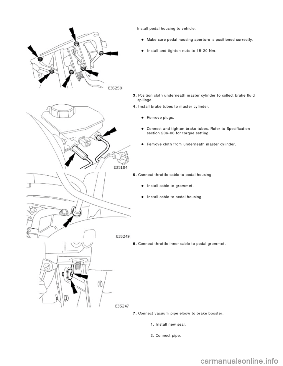
Install peda
l housing to vehicle.
пЃ¬Make sure ped
al housing apertu
re is positioned correctly.
пЃ¬Inst
all and tighten nuts to 15-20 Nm.
3. Position cloth underneath master cylinder to collect brake fluid
spillage.
4. Inst
all brake tubes to master cylinder.
пЃ¬Re
move plugs.
пЃ¬Connect
and tighten brake tubes. Refer to Specification
section 206-06 for torque setting.
пЃ¬R
emove cloth from underneath master cylinder.
5. Con
nect throttle cabl
e to pedal housing.
пЃ¬Inst
all cable to grommet.
пЃ¬Inst
all cable to
pedal housing.
6. Conne
ct throttle inner ca
ble to pedal grommet.
7. Connect vacuum pipe elbow to brake booster.
1. Install new seal.
2. Connect pipe.
Page 421 of 2490
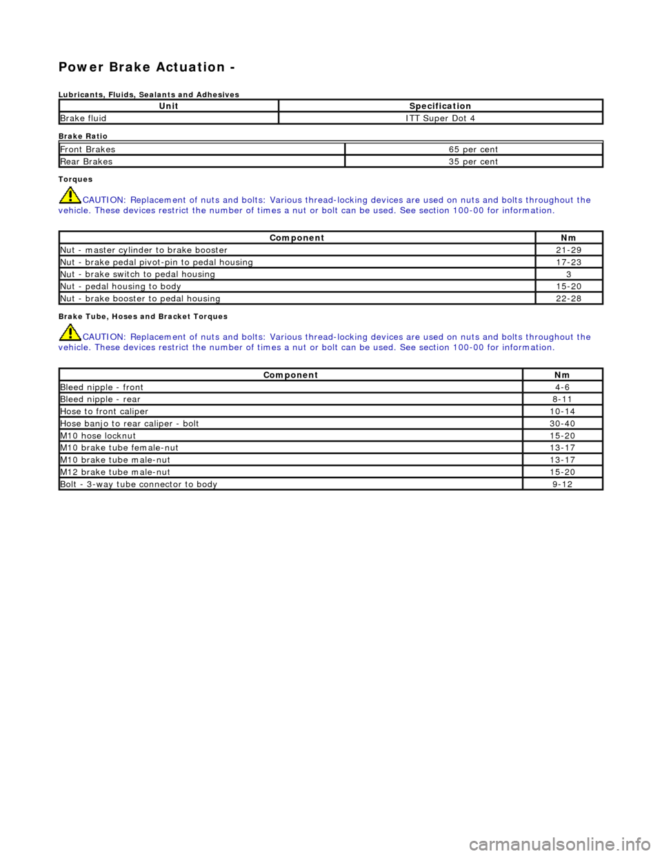
Power Brake Actuation -
Lubri
cants, Fluids, Sealants and Adhesives
Brake Ratio
Torques
CAUTI
ON: Replacement of
nuts and bolts: Various thread-locking devices are used on nuts and bolts throughout the
vehicle. These devices restrict the number of times a nut or bolt can be used. See section 100-00 for information.
B
rake Tube, Hoses and Bracket Torques
CAUTI
ON: Replacement of
nuts and bolts: Various thread-locking devices are used on nuts and bolts throughout the
vehicle. These devices restrict the number of times a nut or bolt can be used. See section 100-00 for information.
UnitS
pecification
Brake flu
id
ITT Supe
r Dot 4
Fr
ont Brakes
6
5 per cent
Rear B
rakes
3
5 per cent
Com
ponent
Nm
N
ut - master cylinder to brake booster
21
-29
Nu
t - brake pedal pivot-pin to pedal housing
17
-23
Nu
t - brake switch to pedal housing
3
Nu
t - pedal housing to body
15
-20
Nu
t - brake booster to pedal housing
22
-28
Com
ponent
Nm
Bleed n
ipple - front
4-
6
Bleed n
ipple - rear
8-
11
Hose to fr
ont caliper
10
-14
Hose banjo to rear caliper -
bolt
30
-40
M1
0 hose locknut
15
-20
M10
brake tube female-nut
13
-17
M10
brake tube male-nut
13
-17
M12
brake tube male-nut
15
-20
Bolt -
3-way tube connector to body
9-
12
Page 429 of 2490
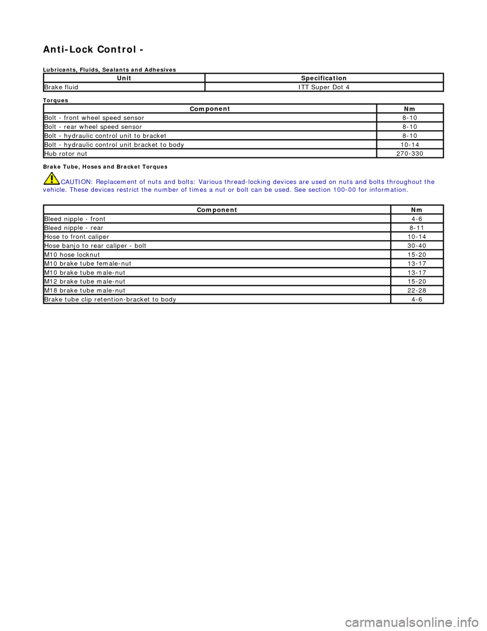
Anti-Lock Control -
Lubri
cants, Fluids, Sealants and Adhesives
Torques
Brake Tube, Hoses and Bracket Torques
CAUTI
ON: Replacement of
nuts and bolts: Various thread-locking devices are used on nuts and bolts throughout the
vehicle. These devices restrict the number of times a nut or bolt can be used. See section 100-00 for information.
UnitS
pecification
Brake flu
id
ITT Supe
r Dot 4
Com
ponent
Nm
Bol
t - front wheel speed sensor
8-
10
Bolt
- rear wheel speed sensor
8-
10
Bo
lt - hydraulic control unit to bracket
8-
10
Bolt -
hydraulic control unit bracket to body
10
-14
Hub rotor nut2
70-330
Com
ponent
Nm
Bleed n
ipple - front
4-
6
Bleed n
ipple - rear
8-1
1
Hose to fr
ont caliper
10
-14
Hose banjo to rear caliper -
bolt
30
-40
M1
0 hose locknut
15
-20
M10
brake tube female-nut
13
-17
M10
brake tube male-nut
13
-17
M12
brake tube male-nut
15
-20
M18
brake tube male-nut
22
-28
Brake tube clip retention
-bracket to body
4-
6
Page 432 of 2490
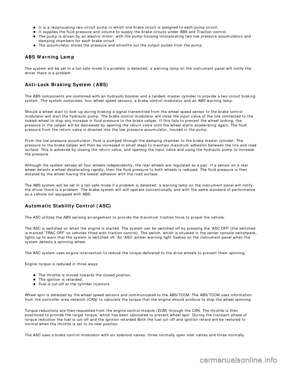
пЃ¬It is a reciprocating two
-circuit pu
mp in which one brake circuit is as signed to each pump circuit.
пЃ¬It supplies th
e fluid pressure and vo
lume to supply the brake circuits under ABS and Traction control.
пЃ¬The pump is driven by an electri
c motor, with the pump
housing incorporating two lo w pressure accumulators and
damping chambers for each brake circuit.
пЃ¬The ac cu
mulator stores the pressure and smooths out the output pu
lses from the pump.
ABS Warning Lamp
The sys
tem will be set in a fail-safe mode if a problem is de
tected; a warning lamp on the instrument panel will notify the
driver there is a problem.
Anti-Lock Braking Sy
stem (ABS)
The AB
S components are combined with
an hydraulic booster and a tandem master cylinder to provide a two circuit braking
system. The system comprises, four wheel speed sensor s, a brake control modulator and an ABS warning lamp.
Should a wheel start to lock-up during braking a signal tr ansmitted from the wheel speed sensor to the brake control
modulator will start the hydraulic pump. The brake control modula tor will close the input valve of the line connected to the
locked-wheel to stop any increase in fluid pressure to the br ake caliper. If this fails to prevent the wheel locking, the
pressure in the caliper will be decreased by opening the return valve until th e wheel starts accelerating again. The fluid
pressure from the return va lve is directed into the low pressure accumulator, housed in the pump.
From the low pressure accumulator, fl uid is pumped through the damping cham ber to the brake master cylinder. The
pressure to the brake caliper will then be increased in small steps to maintain maximum adhesion between the tire and road
surface. This is achieved by closing the return valve, and opening the input valve and using the hydraulic pump to increase
the pressure.
Although the system senses all four wheels independently, the rear wheels are regulated as a pair. If a sensor on a rear
wheel detects a wheel decelerating rapidly, then the fluid pressure to both wheels is reduced. The fluid pressure is then
dictated by the wheel having the lowe st adhesion with the road surface.
The ABS system will be set in a fail-safe mode if a problem is detected; a warn ing lamp on the instrument panel will notify
the driver there is a problem. The brake system will still operate conventionally and with the same standard of performance
as a vehicle not equipped with ABS.
Automa tic Stability Control (ASC)
Th
e ASC utilizes the ABS sensing arrangement to provide the maximum traction force to propel the vehicle.
The ASC is switched on when the engine is started. The system can be switched off by pressing the 'ASC OFF' (the switched
is marked 'TRAC OFF' on vehicles fitted with traction control). The switch, which is situated in the center console switchpack,
lights up to warn that the system is sw itched off. An 'ASC' amber warning light flashes on the instrument panel when the
system detects a spinning wheel.
The ASC system uses engine intervention to reduce the torque delivered to the drive wheels to prevent them spinning.
Engine torque is re duced in three ways:
пЃ¬The
throttle is moved towards the closed position.
пЃ¬The ignition is retarded. пЃ¬F
u
el is cut-off at the cylinder injectors.
Wheel spin is detected by the wheel sp eed sensors and communicated to the AB S/TCCM. The ABS/TCCM uses information
from the controller area network (CAN) to calculate the torque that the engine should produce to stop the wheel spinning.
Torque reductions are then requested from the engine control module (ECM ) through the CAN. The throttle is then
positioned to provide the target torque, which has been calculated to prevent wheel spin. During the transient phase of
torque reduction the fuel is cut-off and th e ignition retarded Both the fuel cut-off an d ignition retard will be restored to
normal when the throttle is set to its new position.
The ASC uses a brake control modulator with six solenoid va lves: three normally open inlet valves and three normally
Page 442 of 2490
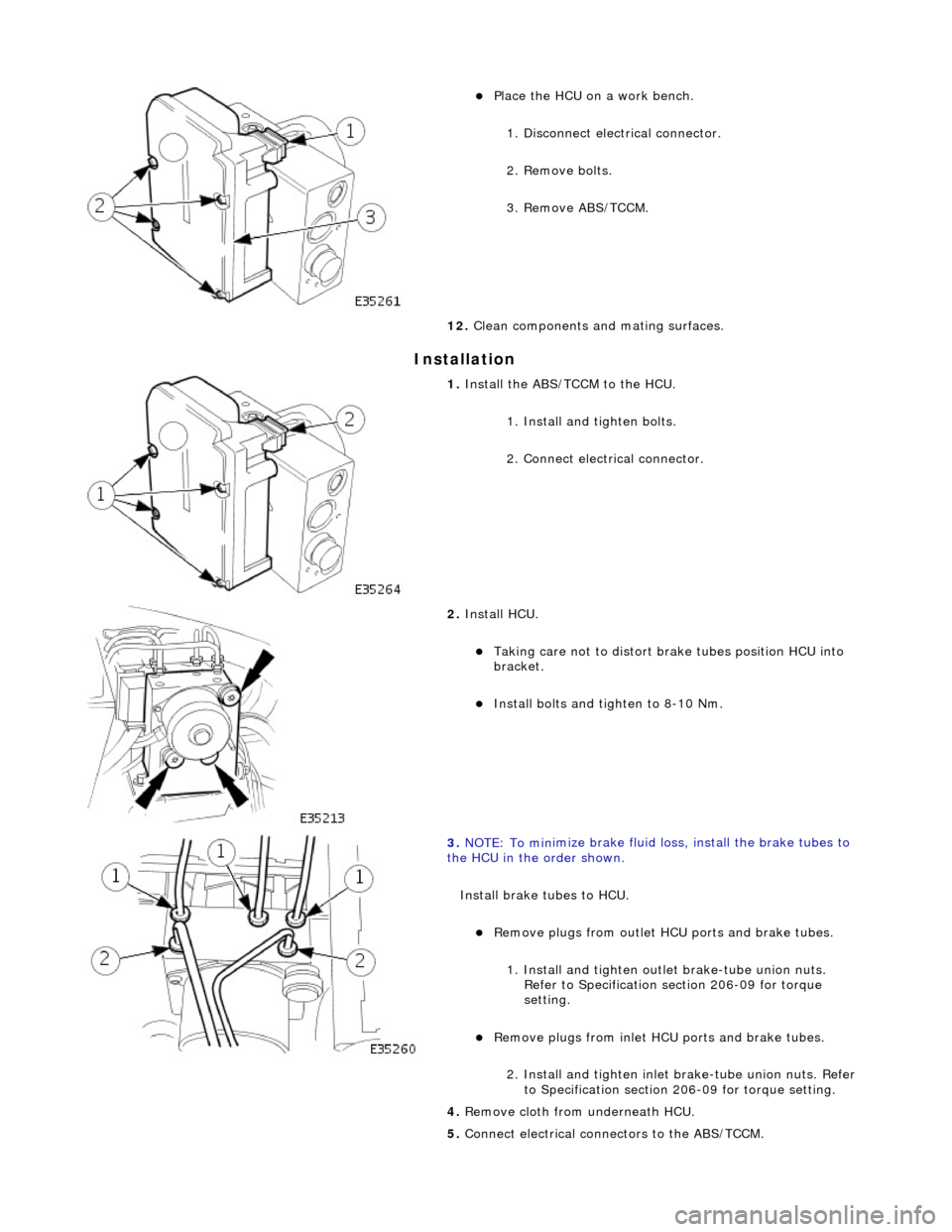
In
stallation
пЃ¬Pla
ce the HCU on a work bench.
1. Disconnect electrical connector.
2. Remove bolts.
3. Remove ABS/TCCM.
12. Clean components and mating surfaces.
1. Install th e AB
S/TCCM to the HCU.
1. Install and tighten bolts.
2. Connect electrical connector.
2. Install HCU.
пЃ¬Takin g
care not to distort brake tubes position HCU into
bracket.
пЃ¬Install bolts and tighten to 8-1
0 Nm.
3. NOTE : To min
imize brake fluid lo
ss, install the brake tubes to
the HCU in the order shown.
Install brake tubes to HCU.
пЃ¬Re
move plugs from outlet HC
U ports and brake tubes.
1. Install and tighten outl et brake-tube union nuts.
Refer to Specification section 206-09 for torque
setting.
пЃ¬Re mo
ve plugs from inlet HC
U ports and brake tubes.
2. Install and tighten inlet brake-tube union nuts. Refer to Specification section 206-09 for torque setting.
4. Remove cloth from underneath HCU.
5. Connect electrical connectors to the ABS/TCCM.
Page 447 of 2490
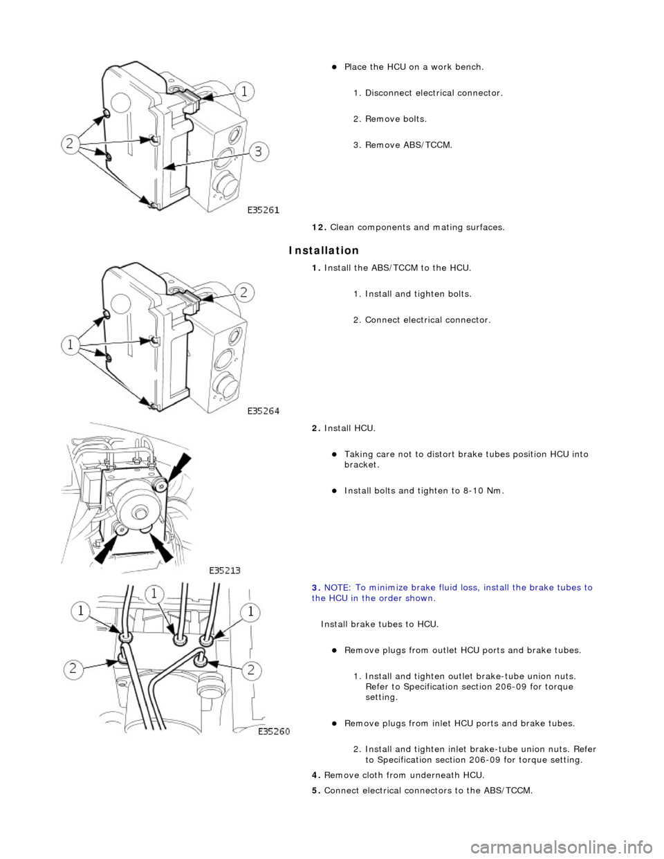
I
nstallation
пЃ¬Pl
ace the HCU on a work bench.
1. Disconnect electrical connector.
2. Remove bolts.
3. Remove ABS/TCCM.
12. Clean components and mating surfaces.
1. Install th
e ABS/TCCM to the HCU.
1. Install and tighten bolts.
2. Connect electrical connector.
2. Install HCU.
пЃ¬Takin
g care not to distort brake tubes position HCU into
bracket.
пЃ¬Install bolts an
d tighten to 8-10 Nm.
3. NOTE
: To minimize brake fluid lo
ss, install the brake tubes to
the HCU in the order shown.
Install brake tubes to HCU.
пЃ¬R
emove plugs from outlet HC
U ports and brake tubes.
1. Install and tighten outl et brake-tube union nuts.
Refer to Specification section 206-09 for torque
setting.
пЃ¬Re
move plugs from inlet HC
U ports and brake tubes.
2. Install and tighten inlet brake-tube union nuts. Refer to Specification section 206-09 for torque setting.
4. Remove cloth from underneath HCU.
5. Connect electrical connectors to the ABS/TCCM.
Page 469 of 2490
Buzz (E
lectrical)
A
different steering buzz can be caused by
pulse width modulated (PWM) electric actuators used in variable assist steering
systems. This buzz is felt by turning the ignition key to run without starting the engine and holding onto the steering wheel.
In extreme cases, the buzz can be felt with the engine running also.
Column/Steering Wheel
Shake
Column shake is a low f
requenc
y vertical vibration excited by primary engine vibrations.
Nibble (Shimm
y)
Steeri
ng nibble is a rotary oscillation or
vibration of the steering wheel, which can be excited at a specific vehicle speed.
Nibble is driven by wheel and tire imbalance exciting a suspensi on recession mode, which then translates into steering gear
travel and finally steering wheel nibble.
Shudder (Judd
er)
Shudder i
s a low frequency oscillation of th
e entire steering system (tire, wheels, st eering gear and linkage, etc.) when the
vehicle is steered during static-park or at low sp eeds. Shudder is very dependent on road surface.
Torque Ri
pple
Torque rippl
e is a concern with Electric Power Steering (EPS) sy
stems. Torque ripple is most evident at static-park steering
the wheel very slowly from lock to lock. Torque ripple is primarily caused by motor commutation.
Torque/Veloc
ity Variation
(Phasing/Effort Cycling)
Steeri
ng wheel torque variation oc
curring twice in one revolution is normally as a result of problems with the lower steering
column (intermediate shaft), but foul cond itions generally result in either constant stiffnes s or single point stiffness.
Depending upon the orientation of the joints, the steering can fe el asymmetric (torque falling off in one direction and rising
in the other) or else it can simply have pronounced peaks and troughs as the steering moves from lock to lock.
Wheel Fight
(Kick Back)
W
heel fight is excess feedback of sudden road forces through th
e steering system and back to the driver. It is evaluated at
all vehicle speeds over cobblestones, rough roads, and potholes . The tires, wheels, and suspension generate forces into the
steering systems. Steering friction, hydraulic damping, hydr aulic compliance, mechanical compliance, steering ratio, and
assist gain all affect how much is transmitted to the driver.
Stee
ring Linkage
CAUTI
ON: Steering gear boots must be
handled carefully to avoid damage. Use new clamps when installing steering
gear boots.
Inspect the boots for cuts, deterioration, tw isting or distortion. Check the steering gear boots to make sure they are tight.
Install new boots or clamps as necessary.
• NOTE: The following steps must be carried out with assistance.
1. 1. With the wheels in the straight ahead po sition, gently turn the steering wheel to the left and the right to check for
free play.
2. 2. Free play should be between 0 and 6 mm (0 and 0.24 in) at the steering wheel rim. If the free play exceeds this
limit, either the ball joints are worn, the lower steering column joints are worn or the backlash of the steering gear
is excessive.
Page 478 of 2490
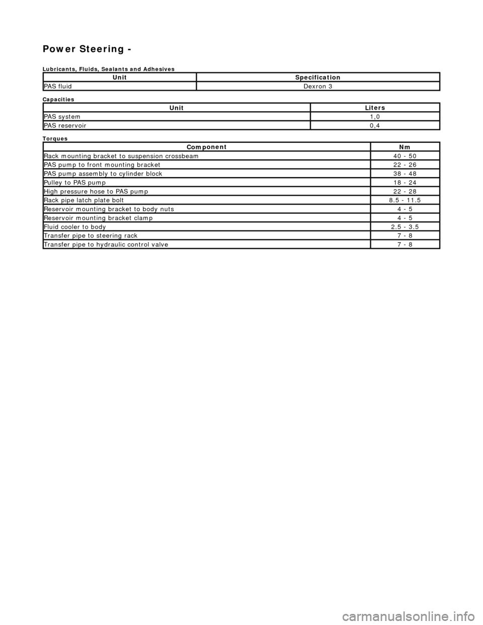
Power Steering -
Lubric
ants, Fluids, Sealants and Adhesives
Capacities
Torques
UnitSp
ecification
PAS flu
i
d
De
xr
on 3
UnitLi
t
ers
PAS syste
m1,0
PAS reservoi
r0,4
Com p
onent
Nm
Rac
k
mountin
g brac
ke
t to suspension crossbeam
40
- 50
PAS pump to front mounti
ng bracket
22
-
26
P
AS pu
mp assembly to cylinder block
38
-
48
Pul
l
ey to PAS pump
18
-
24
Hi
gh pressure hose to PAS pump22 -
28
Rack
pipe latch plate bolt8.5 -
11.5
R
e
servoir mounting bracket to body nuts
4 -
5
R
e
servoir mounting bracket clamp
4 -
5
Fluid cooler to body2.
5 -
3.5
Transfer pipe
to steering rack7 -
8
Transfer pipe
to hydraulic con
trol valve
7 -
8
Page 502 of 2490
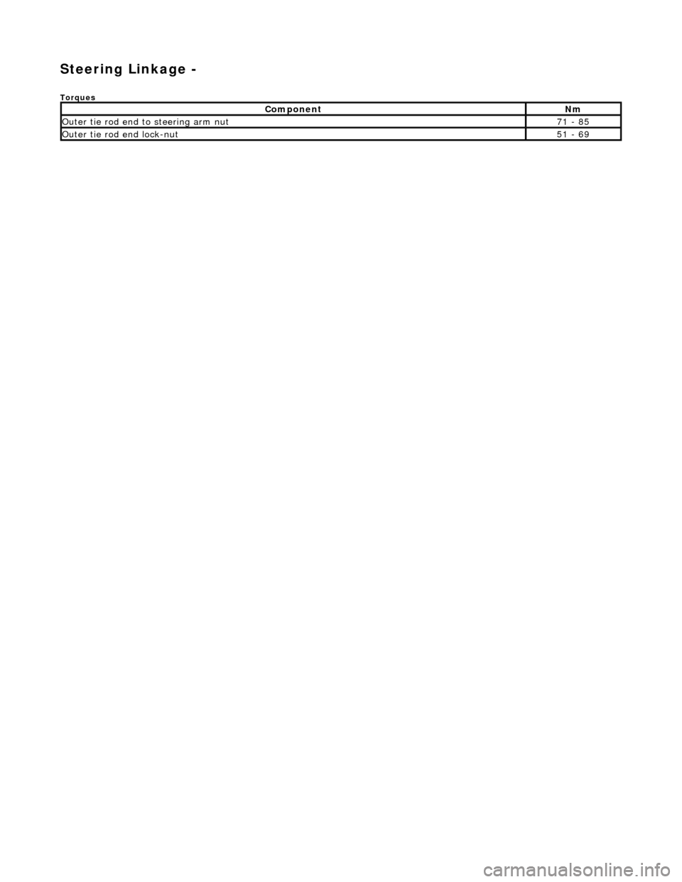
Steering Linkage -
Torques
Comp
onent
Nm
Ou
te
r tie rod end to steering arm nut
71
-
85
Ou
te
r tie rod end lock-nut
51
-
69
Page 504 of 2490
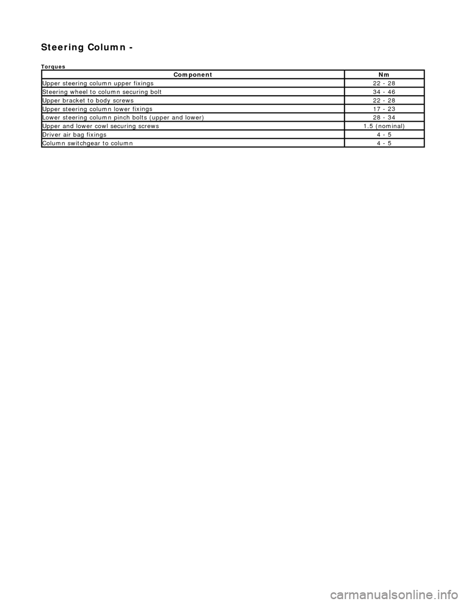
Steering Column -
Torques
Comp
onent
Nm
Upper
steering column upp
er fixings
22
-
28
S
t
eering wheel to column securing bolt
34
-
46
Upper
bracket
to body screws
22
-
28
Upper
steering colu mn lower fi
xings
17
-
23
Lower steeri
ng col
umn pinch bolts (upper and lower)
28
-
34
U
pper
and lower cowl securing screws
1.
5 (
nominal)
D
river ai
r bag fixings
4 -
5
Colum
n switchgear to column
4 -
5