Bolt JAGUAR XFR 2010 1.G Workshop Manual
[x] Cancel search | Manufacturer: JAGUAR, Model Year: 2010, Model line: XFR, Model: JAGUAR XFR 2010 1.GPages: 3039, PDF Size: 58.49 MB
Page 1580 of 3039

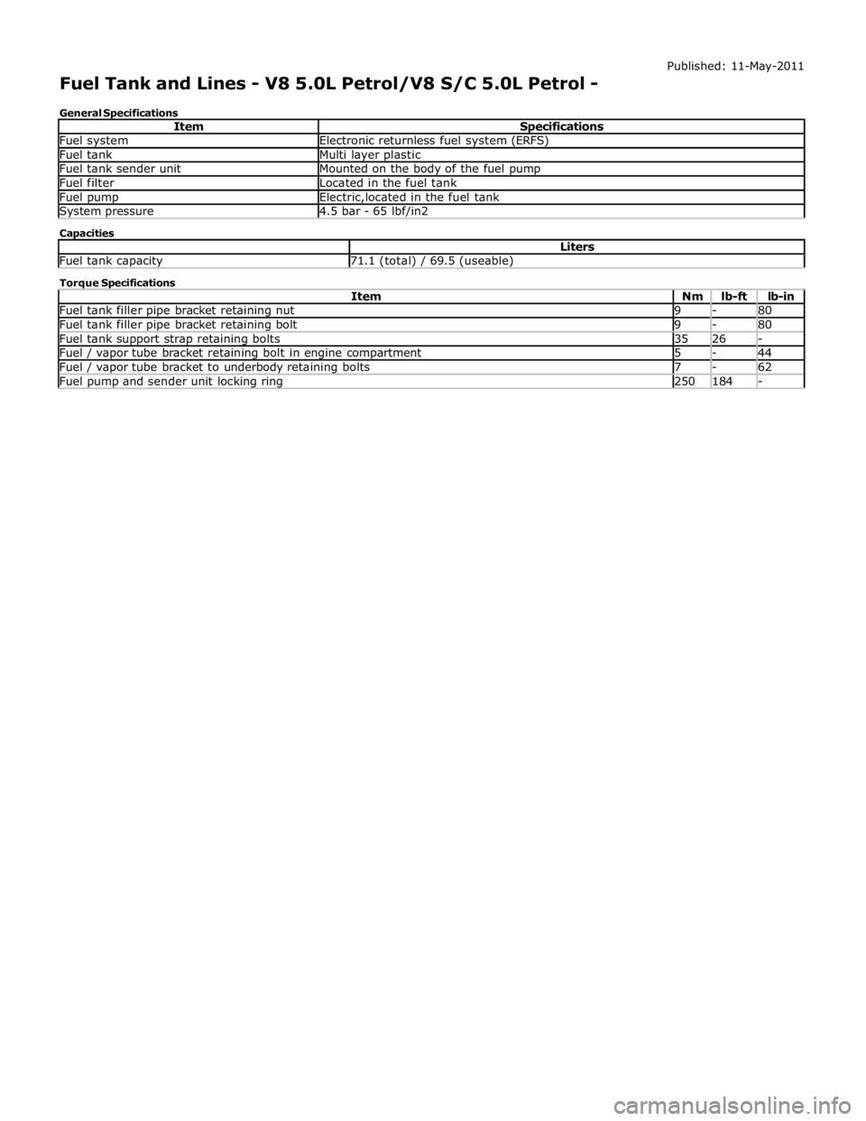
Fuel system Electronic returnless fuel system (ERFS) Fuel tank Multi layer plastic Fuel tank sender unit Mounted on the body of the fuel pump Fuel filter Located in the fuel tank Fuel pump Electric,located in the fuel tank System pressure 4.5 bar - 65 lbf/in2 Capacities Liters Fuel tank capacity 71.1 (total) / 69.5 (useable) Torque Specifications
Item Nm lb-ft lb-in Fuel tank filler pipe bracket retaining nut 9 - 80 Fuel tank filler pipe bracket retaining bolt 9 - 80 Fuel tank support strap retaining bolts 35 26 - Fuel / vapor tube bracket retaining bolt in engine compartment 5 - 44 Fuel / vapor tube bracket to underbody retaining bolts 7 - 62 Fuel pump and sender unit locking ring 250 184 -
Page 1613 of 3039

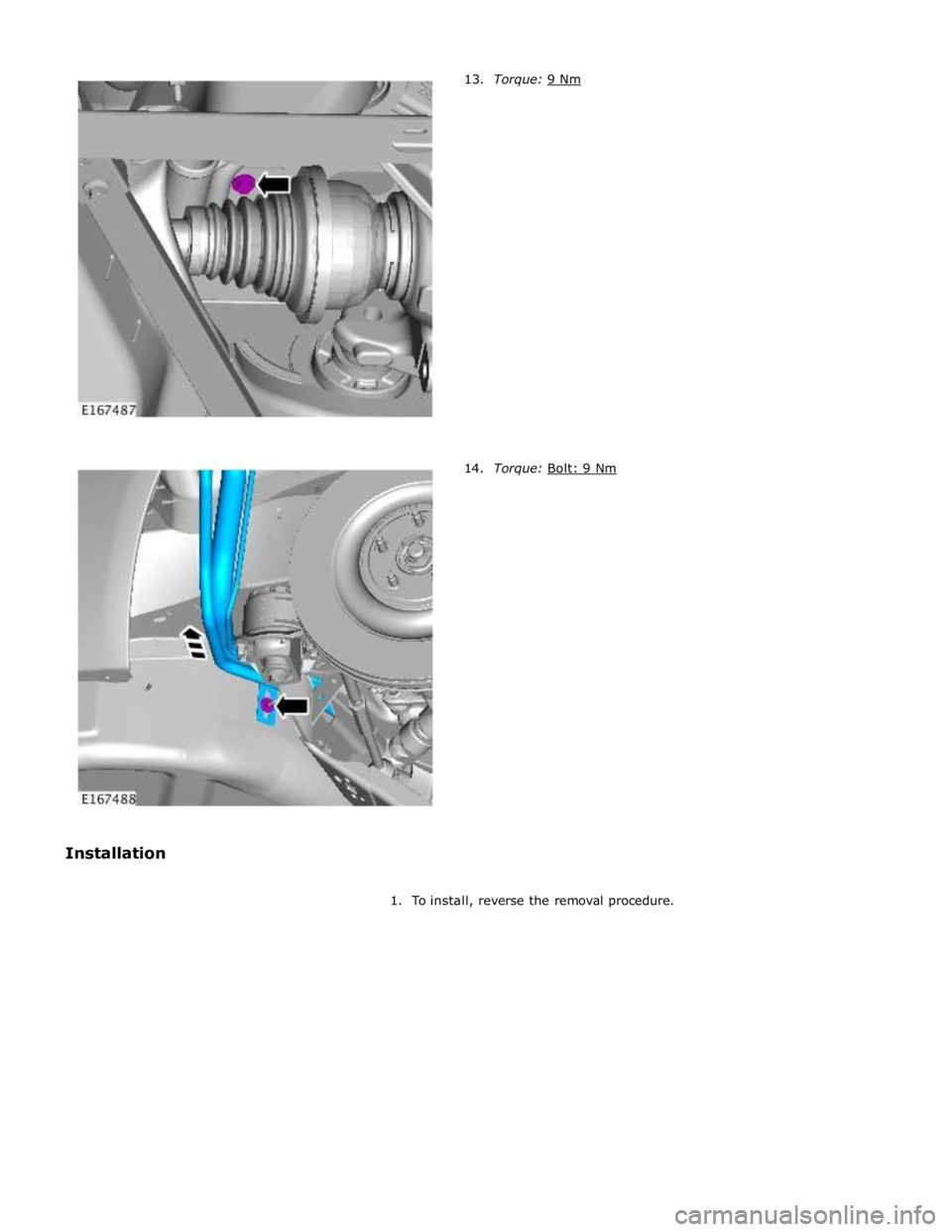
Torque: Bolt: 9 Nm
1. To install, reverse the removal procedure.
Page 1628 of 3039

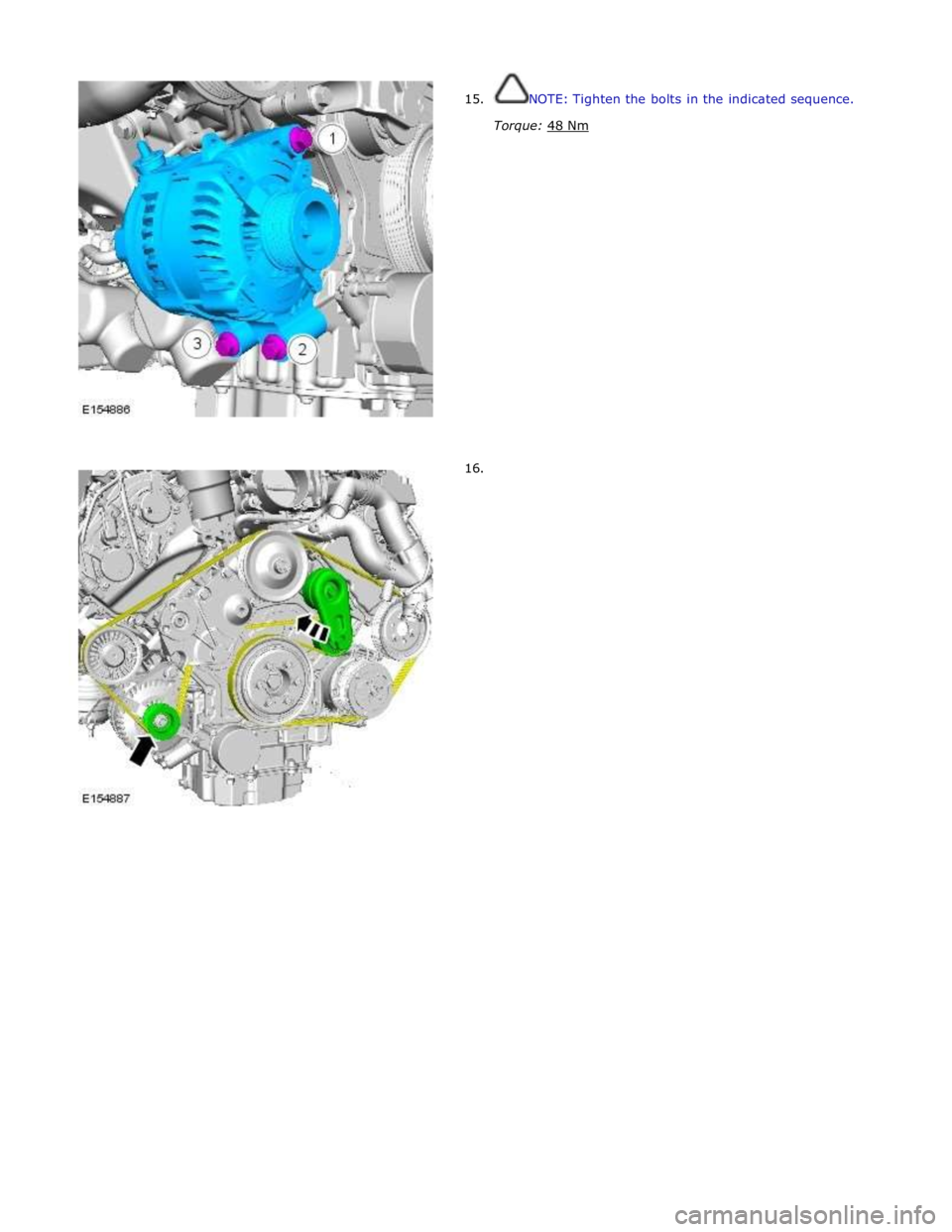
15.
16. NOTE: Tighten the bolts in the indicated sequence.
Torque: 48 Nm
Page 1636 of 3039

Speed control module vertical alignment 90° ± 0.75°
Description Nm lb-ft lb-in Speed control module retaining nuts 5 - 44 Speed control module alignment bolt lock nut 5 - 44
Page 1682 of 3039

Blower motor control module retaining bolts 1 - 9 Foot duct to cross car beam retaining bolt 5 - 44 Climate control assembly to cross car beam retaining bolts 9 - 80 Climate control module retaining bolts 1 - 9 Defrost vent/register blend door actuator retaining bolts 1 - 9 Evaporator pipe bracket retaining bolts 1 - 9 Evaporator housing retaining bolts 1 - 9 Footwell vent/duct blend door actuator retaining bolt 1 - 9 Heater core housing retaining bolts 2 - 18 Sunload sensor retaining bolt 2 - 18 Evaporator core pipes mounting bracket retaining bolts 1 - 9 Evaporator core pipes to thermostatic expansion valve retaining bolt 5 - 44 Thermostatic expansion valve retaining bolts 3 - 26 www.JagDocs.com
Page 1773 of 3039

A/C compressor retaining bolts 25 18 - A/C compressor manifold and tube retaining bolt 9 - 80 A/C condenser core retaining studs 5 - 48 A/C condenser core supply and return lines retaining nuts 8 - 71 Power steering oil cooler retaining nuts 7 - 62 A/C desiccant bag retaining screw (vehicles fitted with petrol engines) 22 16 - A/C desiccant bag retaining screw (vehicles fitted with diesel engines) 4 - 37 A/C pressure cutoff switch 8 - 71
Page 1800 of 3039

DTC Description Possible Cause Action B100D96
Column Lock
Authorisation -
Component
internal failure
Battery voltage at electric
steering column lock control
module too low
Torque load on steering
column
CAN fault
Electric steering column lock
control module - Internal
failure
Clear DTC, repeatedly lock and unlock car using the
key fob and retest
If fault persists, check that the vehicle battery supply
voltage is between 9-16 volts. Rectify as required
Ensure the column lock bolt movement is not
obstructed or restricted (the parked position of the
road wheels may be exerting a turning force through
the steering column, preventing the lock from
releasing. The steering wheel may need to be held
against the force to allow the column lock to
release). Clear DTC, repeatedly lock and unlock car
using the key fob and retest
If fault persists, complete a CAN network integrity
test using the manufacturers approved diagnostic
system. Alternatively, refer to the electrical circuit
diagrams and check CAN circuits between the central
junction box, the instrument cluster and the
electronic steering column lock. Refer to the electrical
circuit diagrams and check the central junction box,
the instrument cluster and the electronic steering
column lock power and ground supply circuits for short
circuit to ground, short circuit to power, open circuit,
high resistance. Repair circuit(s) as required. Clear
DTC, perform an on demand self-test and retest
If fault persists, check and install a new electric
steering column lock control module as required B102487 Start Control Unit
Smart card docking station
failure - slave node not
responding Carry out any pinpoint tests associated with this DTC using
the manufacturer approved diagnostic system. Refer to the
electrical circuit diagrams and check the smart card docking
station LIN circuit for short, open circuit. Suspect the smart
card docking station, check and install a new docking station
as required, refer to the new module/component installation
note at the top of the DTC Index B104611
Front Fog Lamp
Control Switch
Fog lamp switch circuit - short
to ground Refer to the electrical circuit diagrams and check fog lamp
switch circuit for short to ground B104615
Front Fog Lamp
Control Switch
Fog lamp switch circuit - short
to power, open circuit Refer to the electrical circuit diagrams and check fog lamp
switch circuit for short to power, open circuit B104811
Brake Fluid Level
Switch
Brake fluid level switch circuit
- short to ground Refer to the electrical circuit diagrams and check brake fluid
level switch circuit for short to ground B10A011
Wiper/ Washer
Switch
Wash/wipe circuit - short to
ground Refer to the electrical circuit diagrams and check wash/wipe
circuit for short to ground B10A015
Wiper/ Washer
Switch
Wash/wipe circuit - short to
power, open circuit Carry out any pinpoint tests associated with this DTC using
the manufacturer approved diagnostic system. Refer to the
electrical circuit diagrams and check wash/wipe circuit for
short to power, open circuit B10A611 Main Light Switch
Master lighting switch circuit -
short to ground Refer to the electrical circuit diagrams and check master
lighting switch circuit for short to ground B10A615 Main Light Switch
Master lighting switch circuit -
short to power, open circuit Carry out any pinpoint tests associated with this DTC using
the manufacturer approved diagnostic system. Refer to the
electrical circuit diagrams and check master lighting switch
circuit for short to power, open circuit B112B87
Steering Wheel
Module
Steering wheel module failure
- slave node not responding Carry out any pinpoint tests associated with this DTC using
the manufacturer approved diagnostic system. Refer to the
electrical circuit diagrams and check the clockspring LIN
circuit for short, open circuit. Suspect the clockspring, check
and install a new clockspring as required, refer to the new
module/component installation note at the top of the DTC
Index B115C7A
Transfer Fuel
Pump
Fuel pump system fault Check for fuel system jet pump or jet pump fuel level sensor
fault B1A8515
Ambient Light
Sensor
Autolamp sensor circuit - short
to power, open circuit Carry out any pinpoint tests associated with this DTC using
the manufacturer approved diagnostic system. Refer to the
electrical circuit diagrams and check autolamp sensor circuit
for short to power, open circuit
Page 1814 of 3039

Vehicle horn retaining bolt 25 18 -
Page 1875 of 3039

Europe
Rest of
world Vehicles fitted without electrical optional extras Vehicles fitted with electrical optional extras Vehicles fitted with 2.7L diesel engine 90 Ahr 90 Ahr 90
Ahr Vehicles fitted with 3.0L petrol engine 80 Ahr 90 Ahr 90
Ahr Vehicles fitted with 4.2L petrol engine 90 Ahr 90 Ahr 90
Ahr Battery cold cranking Specification
Item Specification 90 Ahr 800 Amps 80 Ahr 700 Amps Torque Specifications
Description Nm lb-ft lb-in Battery positive cable to rear junction box retaining nut 12 9 - Battery monitoring system retaining nut to battery positive terminal 5 - 44 Battery ground cable to body retaining bolt 12 9 - Battery tray 10 - 89 Battery cable terminal 6 - 53 Battery clamp bolt 8 - 71
Page 1886 of 3039

the secondary battery (if fitted) and passes through a grommet in the floorpan.
On new vehicles the primary battery positive terminal is fitted with a transit relay. The transit relay must removed using the
correct process detailed in the Pre Delivery Inspection (PDI) manual.
The battery negative terminal is fitted with a BMS control module. The control module is integral with the battery negative
cable and communicates with the GWM via a LIN bus connection. The battery condition information is passed to the GWM
which controls the generator output accordingly.
CAUTION: To avoid damage to the BMS control module, always use the body ground point in the engine compartment and
not the battery negative terminal when connecting a slave power supply.
Failure to use the recommended ground point will lead to the setting of a DTC. Incorrect information of battery condition will
be retained by the BMS control module due to the unmonitored current flow into the battery. The system will however,
recognize and compensate for the change in battery status after a period of time.
If a new battery is fitted, the BMS control module will require re-calibration using a Jaguar approved diagnostic system.
Replacement of the BMS control module requires no action as the control module will re-calibrate automatically.
SECONDARY BATTERY - DUAL BATTERY VEHICLES ONLY
The secondary battery is located in a tray on the next of the primary battery and is secured to the DBJB with a bracket. The
battery negative (-) terminal is connected via a cable to the vehicle body. The positive (+) terminal is connected by a cable to
the DBJB. The battery is vented via a tube which is connected with a T piece to the vent from the primary battery and passes
through a grommet in the floorpan.
The state of charge of the secondary battery is monitored by the Gateway Module (GWM).
BATTERY MONITORING SYSTEM (BMS)
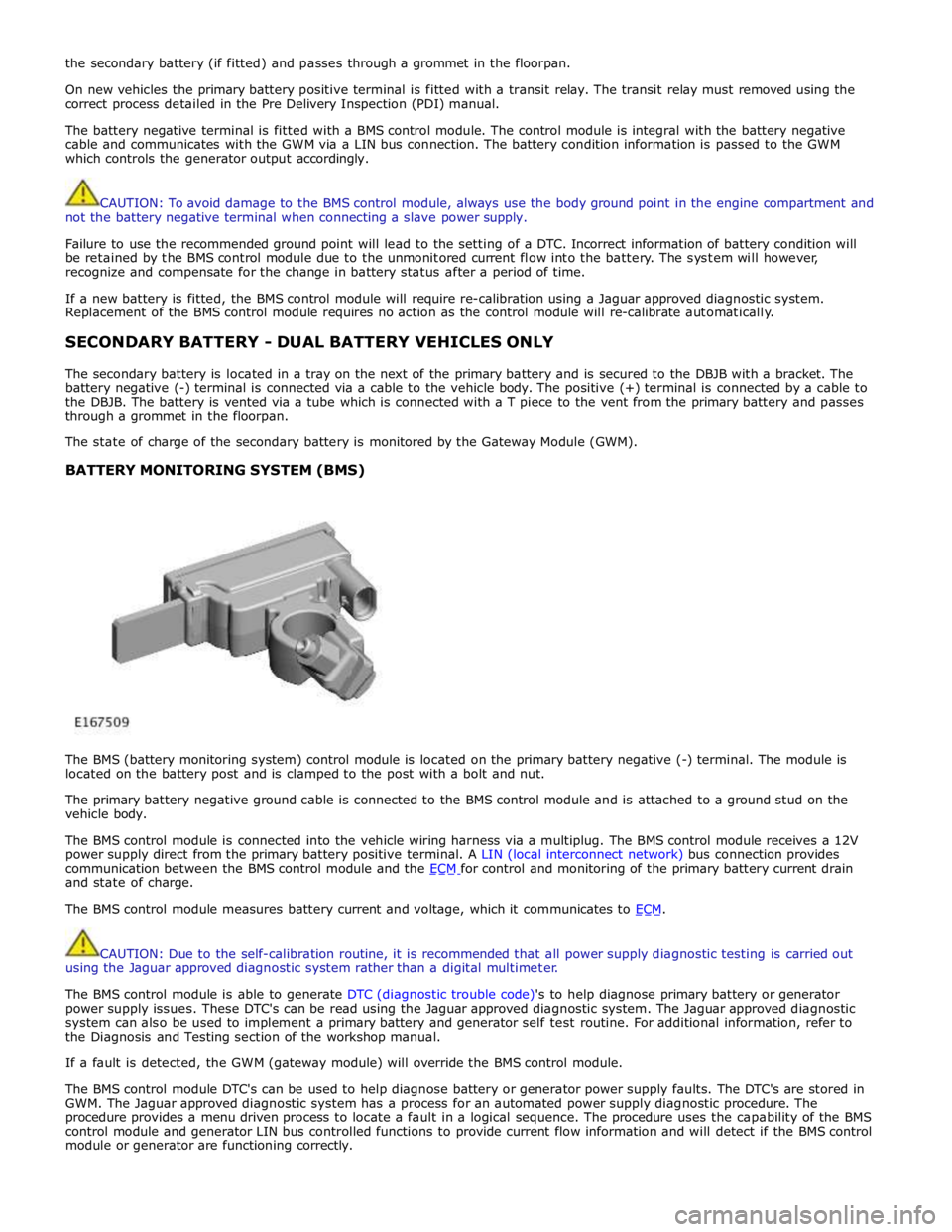
The BMS (battery monitoring system) control module is located on the primary battery negative (-) terminal. The module is
located on the battery post and is clamped to the post with a bolt and nut.
The primary battery negative ground cable is connected to the BMS control module and is attached to a ground stud on the
vehicle body.
The BMS control module is connected into the vehicle wiring harness via a multiplug. The BMS control module receives a 12V
power supply direct from the primary battery positive terminal. A LIN (local interconnect network) bus connection provides
communication between the BMS control module and the ECM for control and monitoring of the primary battery current drain and state of charge.
The BMS control module measures battery current and voltage, which it communicates to ECM.
CAUTION: Due to the self-calibration routine, it is recommended that all power supply diagnostic testing is carried out
using the Jaguar approved diagnostic system rather than a digital multimeter.
The BMS control module is able to generate DTC (diagnostic trouble code)'s to help diagnose primary battery or generator
power supply issues. These DTC's can be read using the Jaguar approved diagnostic system. The Jaguar approved diagnostic
system can also be used to implement a primary battery and generator self test routine. For additional information, refer to
the Diagnosis and Testing section of the workshop manual.
If a fault is detected, the GWM (gateway module) will override the BMS control module.
The BMS control module DTC's can be used to help diagnose battery or generator power supply faults. The DTC's are stored in
GWM. The Jaguar approved diagnostic system has a process for an automated power supply diagnostic procedure. The
procedure provides a menu driven process to locate a fault in a logical sequence. The procedure uses the capability of the BMS
control module and generator LIN bus controlled functions to provide current flow information and will detect if the BMS control
module or generator are functioning correctly.