Bolt JAGUAR XFR 2010 1.G Workshop Manual
[x] Cancel search | Manufacturer: JAGUAR, Model Year: 2010, Model line: XFR, Model: JAGUAR XFR 2010 1.GPages: 3039, PDF Size: 58.49 MB
Page 1353 of 3039
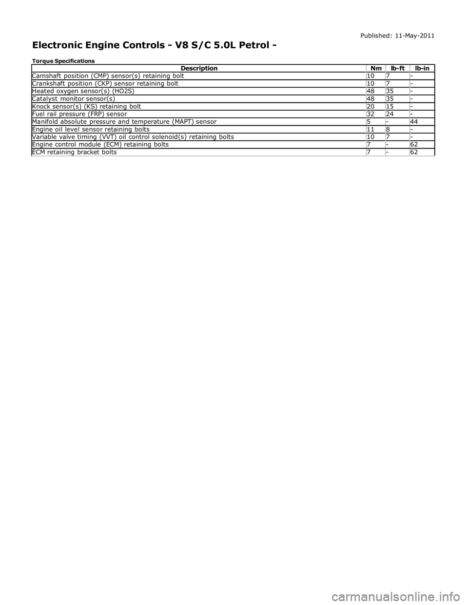
Camshaft position (CMP) sensor(s) retaining bolt 10 7 - Crankshaft position (CKP) sensor retaining bolt 10 7 - Heated oxygen sensor(s) (HO2S) 48 35 - Catalyst monitor sensor(s) 48 35 - Knock sensor(s) (KS) retaining bolt 20 15 - Fuel rail pressure (FRP) sensor 32 24 - Manifold absolute pressure and temperature (MAPT) sensor 5 - 44 Engine oil level sensor retaining bolts 11 8 - Variable valve timing (VVT) oil control solenoid(s) retaining bolts 10 7 - Engine control module (ECM) retaining bolts 7 - 62 ECM retaining bracket bolts 7 - 62
Page 1408 of 3039
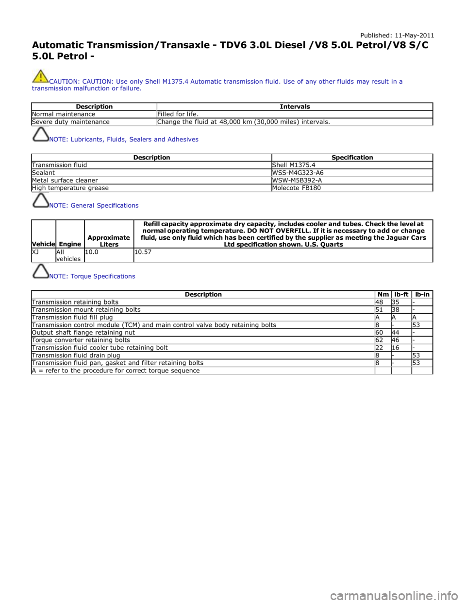
Published: 11-May-2011
Automatic Transmission/Transaxle - TDV6 3.0L Diesel /V8 5.0L Petrol/V8 S/C 5.0L Petrol -
CAUTION: CAUTION: Use only Shell M1375.4 Automatic transmission fluid. Use of any other fluids may result in a
transmission malfunction or failure.
Description Intervals Normal maintenance Filled for life. Severe duty maintenance Change the fluid at 48,000 km (30,000 miles) intervals.
NOTE: Lubricants, Fluids, Sealers and Adhesives
Description Specification Transmission fluid Shell M1375.4 Sealant WSS-M4G323-A6 Metal surface cleaner WSW-M5B392-A High temperature grease Molecote FB180
NOTE: General Specifications
Vehicle
Engine
Approximate
Liters Refill capacity approximate dry capacity, includes cooler and tubes. Check the level at
normal operating temperature. DO NOT OVERFILL. If it is necessary to add or change
fluid, use only fluid which has been certified by the supplier as meeting the Jaguar Cars
Ltd specification shown. U.S. Quarts XJ
All
vehicles 10.0 10.57
NOTE: Torque Specifications
Description Nm lb-ft lb-in Transmission retaining bolts 48 35 - Transmission mount retaining bolts 51 38 - Transmission fluid fill plug A A A Transmission control module (TCM) and main control valve body retaining bolts 8 - 53 Output shaft flange retaining nut 60 44 - Torque converter retaining bolts 62 46 - Transmission fluid cooler tube retaining bolt 22 16 - Transmission fluid drain plug 8 - 53 Transmission fluid pan, gasket and filter retaining bolts 8 - 53 A = refer to the procedure for correct torque sequence
Page 1423 of 3039
The TCM can be reprogrammed using a Jaguar approved diagnostic system using a flash code. The TCM processor has a 440 kb internal flash memory. Of this capacity, approximately 370 kb are used by the basic transmission program. The remainder,
approximately 70 kb is used to store vehicle-specific application data.
Engine Stall
If the vehicle stalls it will coast down in gear, with the transmission providing drive to the engine. A restart can be attempted
at this point and the engine may start and the driver can continue.
If the coast down speed reduces such that the speed of the engine is less than 600 rev/min, the transmission will go to
neutral, D illumination will flash in the instrument cluster. The driver needs to select neutral or park and then press the brake
pedal to restart the engine.
If the start/stop button is pressed when driving, the message ENGINE STOP BUTTON PRESSED is displayed in the message
center but there will be no change to the ignition state. If the driver requires to switch off the engine, the start/stop button
must be pressed for a second time. The engine will be stopped and will be back driven by the transmission as the vehicle
coasts down. When the engine speed is less than 600 rev/min the transmission engages neutral (flashing D illumination in the
instrument cluster). When vehicle speed is less than 2 km/h (1.2 mph) Park is engaged. The JaguarDrive selector automatically
rotates back to its lowered P position and the vehicle ignition is switched off.
The park engagement is prevented in a stall case as the ignition power is on and D was the last selected gear. The park
engagement speed at ignition off is from the least value of the wheel speeds (CAN signal) and transmission output speed (internal signal).
TRANSMISSION Component Description
The transmission comprises the main casing which houses all of the transmission components. The main casing also
incorporates an integral bell housing.
A fluid pan is attached to the lower face of the main casing and is secured with bolts. The fluid pan is sealed to the main
casing with a gasket. Removal of the fluid pan allows access to the Mechatronic valve block. The fluid pan has a magnet
located around the drain plug which collects any metallic particles present in the transmission fluid.
A fluid filter is located inside the fluid pan. If the transmission fluid becomes contaminated or after any service work, the fluid
pan with integral filter must be replaced.
The integral bell housing provides protection for the torque converter assembly and also provides the attachment for the
gearbox to the engine cylinder block. The torque converter is a non-serviceable assembly which also contains the lock-up clutch
mechanism. The torque converter drives a crescent type pump via drive tangs. The fluid pump is located in the main casing,
behind the torque converter.
The main casing contains the following major components:
Input shaft
Output shaft
Mechatronic valve block which contains the solenoids, speed sensors and the TCM Three rotating multiplate drive clutches
Two fixed multiplate brake clutches
A single planetary gear train and a double planetary gear train.
Page 1474 of 3039
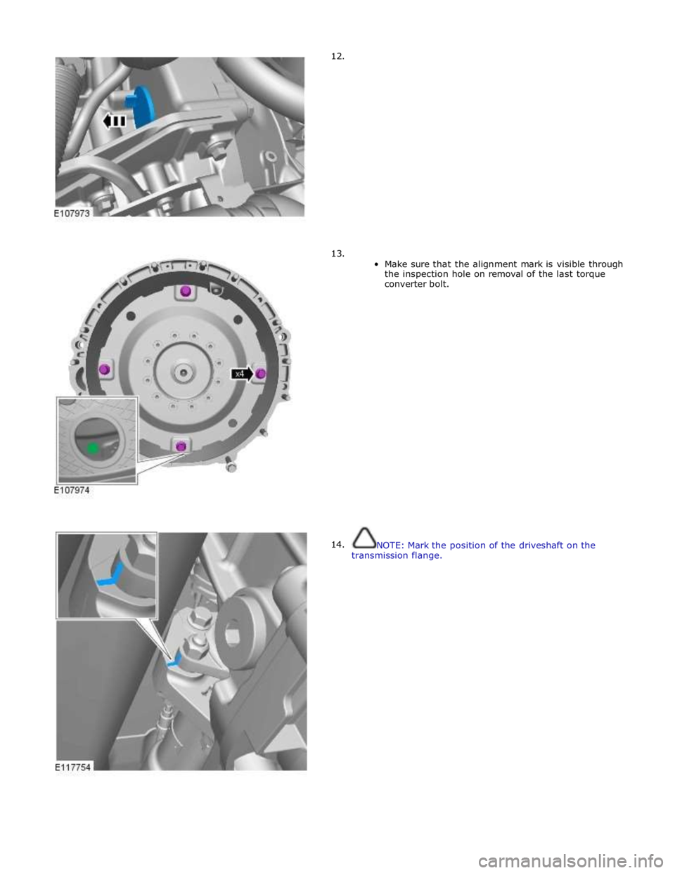
12.
13.
14.
Make sure that the alignment mark is visible through
the inspection hole on removal of the last torque
converter bolt.
NOTE: Mark the position of the driveshaft on the
transmission flange.
Page 1491 of 3039
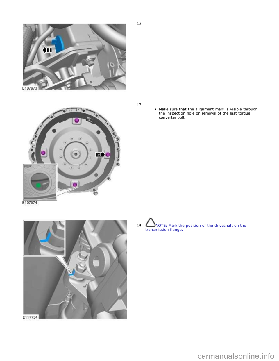
12.
13.
14.
Make sure that the alignment mark is visible through
the inspection hole on removal of the last torque
converter bolt.
NOTE: Mark the position of the driveshaft on the
transmission flange.
Page 1507 of 3039
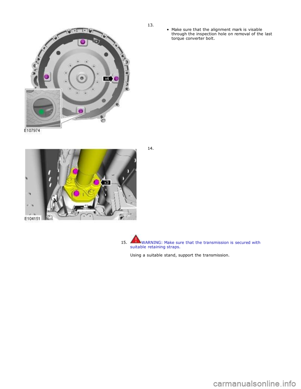
13.
14.
Make sure that the alignment mark is visable
through the inspection hole on removal of the last
torque converter bolt.
15.
WARNING: Make sure that the transmission is secured with
suitable retaining straps.
Using a suitable stand, support the transmission.
Page 1517 of 3039

Transmission fluid ATF Shell M 1375.4 Vehicles with 3.0L diesel engine
Description Nm lb-ft Transmission fluid cooler tube to transmission housing bolt 23 17 Transmission fluid cooler tube bracket to engine oil pan retaining bolt 23 17 Vehicles with 5.0L engine
Description Nm lb-ft Transmission fluid cooler tube to transmission housing bolt 23 17 Transmission fluid cooler tube bracket to engine oil pan retaining bolt 11 8
Page 1526 of 3039
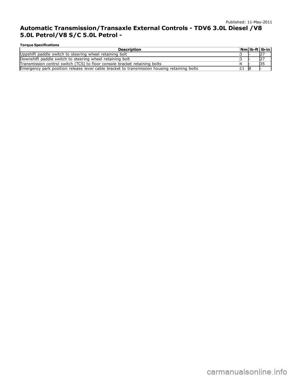
Uppshift paddle switch to steering wheel retaining bolt 3 - 27 Downshift paddle switch to steering wheel retaining bolt 3 - 27 Transmission control switch (TCS) to floor console bracket retaining bolts 4 - 35 Emergency park position release lever cable bracket to transmission housing retaining bolts 11 8 -
Page 1544 of 3039

Catalytic converter retaining bolts 40 30 - Rear muffler support retaining bolts 25 18 - Exhaust securing strap nuts 55 40 - Exhaust support retaining bolts 25 18 -
Page 1546 of 3039

Published: 11-May-2011
Exhaust System - V8 5.0L Petrol/V8 S/C 5.0L Petrol - Exhaust System - Overview
Description and Operation
OVERVIEW
5.0L V8 NATURALLY ASPIRATED AND SUPERCHARGER - FROM 2010MY
The exhaust system fitted to models with the 5.0L V8 engines are fabricated from stainless steel. 5 separate assemblies make
up the complete system.
The front section comprises 2 separate assemblies (LH (left-hand) and RH (right-hand)) incorporating a catalytic converter for
each bank of cylinders. The rear section comprises 3 separate sections; a center section and two rear sections. The center
section assembly incorporates a rear silencer which is connected to a center resonator silencer. On supercharger models, the
center resonator is a one piece assembly with two inlet pipes from the center silencer and two outlet pipes to the rear
silencers. On naturally aspirated models, each outlet pipe from the center silencer connects into an individual center resonator.
The system is attached to the underside of the body with mounting rubbers which are located on steel hanger bars that are
welded to the system. The mounting rubbers locate on corresponding hangers which are welded or bolted to the underside of
the vehicle body.