JAGUAR XFR 2010 1.G Workshop Manual
Manufacturer: JAGUAR, Model Year: 2010, Model line: XFR, Model: JAGUAR XFR 2010 1.GPages: 3039, PDF Size: 58.49 MB
Page 1851 of 3039

Mechanical Electrical Parking aid control module
Parking aid sounder
Audio system
4. If an obvious cause for an observed or reported concern is found, correct the cause (if possible) before proceeding to
the next step
5. If the cause is not visually evident, check for diagnostic trouble codes (DTCs) and refer to the DTC index
Symptom Chart
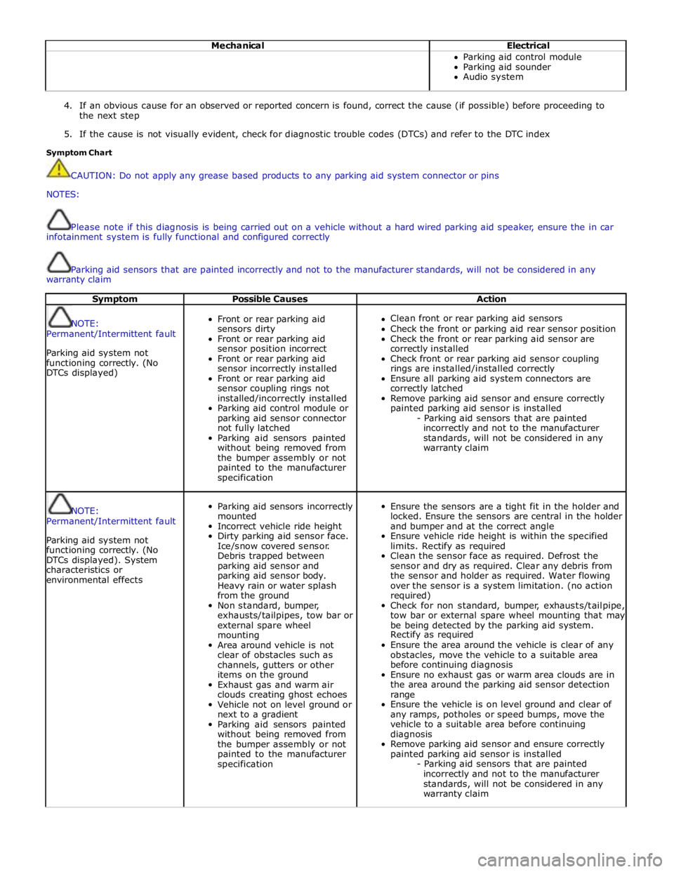
CAUTION: Do not apply any grease based products to any parking aid system connector or pins
NOTES:
Please note if this diagnosis is being carried out on a vehicle without a hard wired parking aid speaker, ensure the in car
infotainment system is fully functional and configured correctly
Parking aid sensors that are painted incorrectly and not to the manufacturer standards, will not be considered in any
warranty claim
Symptom Possible Causes Action
NOTE:
Permanent/Intermittent fault
Parking aid system not
functioning correctly. (No
DTCs displayed)
Front or rear parking aid
sensors dirty
Front or rear parking aid
sensor position incorrect
Front or rear parking aid
sensor incorrectly installed
Front or rear parking aid
sensor coupling rings not
installed/incorrectly installed
Parking aid control module or
parking aid sensor connector
not fully latched
Parking aid sensors painted
without being removed from
the bumper assembly or not
painted to the manufacturer
specification
Clean front or rear parking aid sensors
Check the front or parking aid rear sensor position
Check the front or rear parking aid sensor are
correctly installed
Check front or rear parking aid sensor coupling
rings are installed/installed correctly
Ensure all parking aid system connectors are
correctly latched
Remove parking aid sensor and ensure correctly
painted parking aid sensor is installed
- Parking aid sensors that are painted
incorrectly and not to the manufacturer
standards, will not be considered in any
warranty claim
NOTE:
Permanent/Intermittent fault
Parking aid system not
functioning correctly. (No
DTCs displayed). System
characteristics or
environmental effects
Parking aid sensors incorrectly
mounted
Incorrect vehicle ride height
Dirty parking aid sensor face.
Ice/snow covered sensor.
Debris trapped between
parking aid sensor and
parking aid sensor body.
Heavy rain or water splash
from the ground
Non standard, bumper,
exhausts/tailpipes, tow bar or
external spare wheel
mounting
Area around vehicle is not
clear of obstacles such as
channels, gutters or other
items on the ground
Exhaust gas and warm air
clouds creating ghost echoes
Vehicle not on level ground or
next to a gradient
Parking aid sensors painted
without being removed from
the bumper assembly or not
painted to the manufacturer
specification
Ensure the sensors are a tight fit in the holder and
locked. Ensure the sensors are central in the holder
and bumper and at the correct angle
Ensure vehicle ride height is within the specified
limits. Rectify as required
Clean the sensor face as required. Defrost the
sensor and dry as required. Clear any debris from
the sensor and holder as required. Water flowing
over the sensor is a system limitation. (no action
required)
Check for non standard, bumper, exhausts/tailpipe,
tow bar or external spare wheel mounting that may
be being detected by the parking aid system.
Rectify as required
Ensure the area around the vehicle is clear of any
obstacles, move the vehicle to a suitable area
before continuing diagnosis
Ensure no exhaust gas or warm area clouds are in
the area around the parking aid sensor detection
range
Ensure the vehicle is on level ground and clear of
any ramps, potholes or speed bumps, move the
vehicle to a suitable area before continuing
diagnosis
Remove parking aid sensor and ensure correctly
painted parking aid sensor is installed
- Parking aid sensors that are painted
incorrectly and not to the manufacturer
standards, will not be considered in any
warranty claim
Page 1852 of 3039

Symptom Possible Causes Action Parking aid sensors are being
returned with no faults found
or signs of water
ingress/corrosion Possible issue with sensor connectors
not latched correctly
When either no/intermittent operation has been
reported the following action should be taken
1. Using Datalogger, identify the position of the
suspect parking aid sensor within the bumper
2. Visually locate the position of the suspect
parking aid sensor. Inspect and provide details in
claim if the sensor has any sign of physical
damage
3. Remove the bumper. Disconnect the wiring at
the main harness connector. Inspect the main
harness connectors and terminals for signs of
damage, backed out pins, corrosion and water
ingress, or damage to the seals. Provide details in
claim if any of the above symptoms are present
4. Attempt to remove the harness connector from
the suspect parking aid sensor without using the
connector latch i.e. lightly pull back on ALL wires
together, ensuring the harness is held close to the
back of the connector, not elsewhere on the wiring
harness. DO NOT apply excessive force. If the
connector can be removed without using the latch,
provide details in claim if connector is loose. If the
connector is fully latched, disconnect it from the
sensor
5. Inspect and provide details in claim if the
suspect sensor harness connector has any sign of
water ingress/corrosion
6. Inspect and provide details in claim if the
suspect parking aid sensor harness connector
shows any sign that the terminals have backed-out
of the connector or for any damage to the terminal
seals. Replace/repair the harness as required and
proceed
7. Remove the suspect parking aid sensor from the
bumper. Inspect the parking aid sensor connector
for signs of water ingress/corrosion. Provide details
in claim if corrosion/water ingress is present
8. Exchange the suspect parking aid sensor with
another parking aid sensor within the bumper that
is performing correctly. Reconnect all sensors and
reconnect the bumper main harness connector.
Repeat step 1. Confirm if the original fault now
appears at the new position of the suspect parking
aid sensor, if so, proceed to step 10
9. If not, carry out the appropriate open circuit and
short circuit checks between the original suspect
parking aid sensor harness connector and the
parking aid control module
10. Refit the parking aid sensors to their original
position in the bumper
11. Reconnect the parking aid sensor to the
bumper harness connector. Reconnect main harness
connector and refit the bumper
12. Repeat Step 1. If fault is still present, replace
only the faulty sensor
PINPOINT TEST A : PARKING AID SYSTEM NOT FUNCTIONING CORRECTLY WITH NO DTCS LOGGED TEST
CONDITIONS DETAILS/RESULTS/ACTIONS A1: PERMANENT FAULT 1 When the parking aid system is activated, there is a vibration on the parking aid sensor membrane. This can be verified by touching the parking aid sensor face with a hard item such as a pencil, ball-pen, small
screwdriver, or fingernail. Ensure no damage is caused to sensor painted surface Are the parking aid sensor(s) vibrating? Yes
GO to A2. No
GO to A5. A2: SENSORS VIBRATING WITH PARKING AID FAULT 1 Clean the parking aid sensor face Parking aid system functioning correctly? Yes
No further action required
No www.JagDocs.com
Page 1853 of 3039

A3: SENSORS VIBRATING WITH PARKING AID FAULT 1 Check parking aid sensors correctly mounted. Parking aid sensor holder correctly mounted. Parking aid sensor decoupler ring fitted or fitted correctly. Parking aid sensor positioning correct. Parking aid sensor
painted without being removed from the bumper assembly or not painted to manufacturer specification.
Rectify as required Parking aid system functioning correctly? Yes
No further action required
No
GO to A4. A4: SENSORS VIBRATING WITH PARKING AID FAULT 1 Carry out speaker test. Only applicable to vehicles with rear hard wired parking aid speakers. Check the parking aid speaker wiring circuit and connector. Rectify as required. Check and install a new parking aid
speaker as required. Vehicles with audio parking aid system. Confirm audio system is functioning
correctly. Refer to the relevant section of the workshop manual Parking aid system functioning correctly Yes
No further action required A5: SENSORS NOT VIBRATING WITH PARKING AID FAULT 1 Isolate the fault to front or rear parking aid sensors Are all rear parking aid sensors vibrating? Yes
GO to A6. No
GO to A10. A6: FRONT SENSORS NOT VIBRATING WITH PARKING AID FAULT 1 Check the parking aid control module is correctly configured. Check and update the car configuration file as required Parking aid system functioning correctly? Yes
No further action required
No
GO to A7. A7: FRONT SENSORS NOT VIBRATING WITH PARKING AID FAULT 1 Check the correct parking aid control module is installed to the vehicle Parking aid system functioning correctly? Yes
No further action required
No
GO to A8. A8: FRONT SENSORS NOT VIBRATING WITH PARKING AID FAULT 1 If all 4 front parking aid sensors are not vibrating, carry out harness test on common ground, power supply. Check main parking aid harness connector to bumper harness connector. Rectify as required Parking aid system functioning correctly? Yes
No further action required
No
GO to A9. A9: FRONT SENSORS NOT VIBRATING WITH PARKING AID FAULT 1 Check and install a new parking aid control module as required. Refer to the warranty policy and procedures manual, or determine if any prior approval programme is in operation, prior to the installation
of a new module/component Parking aid system functioning correctly Yes
No further action required A10: REAR SENSORS NOT VIBRATING WITH PARKING AID FAULT 1 Check the parking aid control module is correctly configured. Check and update the car configuration file as required Parking aid system functioning correctly? Yes
No further action required
No
GO to A11. A11: REAR SENSORS NOT VIBRATING WITH PARKING AID FAULT 1 If all 4 rear parking aid sensors are not vibrating, carry out harness test on common ground, power supply. Check main parking aid harness connector to bumper harness connector. Rectify as required Parking aid system functioning correctly Yes
No further action required
No
GO to A12. A12: REAR SENSORS NOT VIBRATING WITH PARKING AID FAULT 1 Check and install a new parking aid control module as required. Refer to the warranty policy and procedures manual, or determine if any prior approval programme is in operation, prior to the installation
of a new module/component
Page 1854 of 3039

PINPOINT TEST B : PARKING AID SYSTEM NOT FUNCTIONING CORRECTLY WITH NO DTCS LOGGED TEST
CONDITIONS DETAILS/RESULTS/ACTIONS B1: PARKING AID SYSTEM GIVES WARNING SIGNAL WITHOUT OBSTACLE 1 Clean the parking aid sensor face. Check for any damage to the parking aid sensor face. Rectify as required. Snow, water or ice on sensor face. Parking aid sensor face has been repainted to the incorrect
thickness. Rectify as required Parking aid system functioning correctly? Yes
No further action required
No
GO to B2. B2: PARKING AID SYSTEM GIVES WARNING SIGNAL WITHOUT OBSTACLE 1 Ensure the vehicle ride height is within manufacturer specified limits. Rectify as required Parking aid system functioning correctly? Yes
No further action required
No
GO to B3. B3: PARKING AID SYSTEM GIVES WARNING SIGNAL WITHOUT OBSTACLE 1 Check for any non standard accessories are not fitted, such as tow bar, bike rack, body kit, modified exhaust, lighting or licence plate holder Parking aid system functioning correctly? Yes
No further action required
No
GO to B4. B4: PARKING AID SYSTEM GIVES WARNING SIGNAL WITHOUT OBSTACLE 1 Limitations or characteristics of the parking aid system such as vehicle on a gradient, exhaust gas vapour, signal reflection Parking aid system functioning correctly? Yes
No further action required
No
For a detailed description of the parking aid system, refer to the relevant description and operation
section in the workshop manual.
REFER to: Parking Aid (413-13 Parking Aid, Description and Operation). DTC Index
CAUTION: Diagnosis by substitution from a donor vehicle is NOT acceptable. Substitution of control modules does not
guarantee confirmation of a fault, and may also cause additional faults in the vehicle being tested and/or the donor vehicle.
NOTES:
If the control module is suspect and the vehicle remains under manufacturer warranty, refer to the Warranty Policy and
Procedures manual (section B1.2), or determine if any prior approval programme is in operation, prior to the installation of a
new module.
Generic scan tools may not read the codes listed, or may read only five digit codes. Match the five digits from the scan
tool to the first five digits of the seven digit code listed to identify the fault (the last two digits give additional information
read by the manufacturer approved diagnostic system).
When performing voltage or resistance tests, always use a digital multimeter (DMM) accurate to three decimal places,
and with an up-to-date calibration certificate. When testing resistance always take the resistance of the DMM leads into
account.
Check and rectify basic faults before beginning diagnostic routines involving pinpoint tests.
Inspect connectors for signs of water ingress, and pins for damage and/or corrosion.
If DTCs are recorded and, after performing the pinpoint tests, a fault is not present, an intermittent concern may be the
cause. Always check for loose connections and corroded terminals. Parking aid system functioning correctly
Yes
No further action required
Page 1855 of 3039

Check DDW for open campaigns. Refer to the corresponding bulletins and SSMs which may be valid for the specific
customer complaint and carry out the recommendations as required.
When carrying out repair/diagnosis of the system, on removal of the front or rear bumper inspect the sensor connectors
to ensure they were correctly latched and check fly leads for signs of chaffing or trapped wires
Physical damage to the sensor (impact damage or scratched sensor surface) must NOT be changed under warranty.
DTC Description Possible Causes Action B1B36-01
Front Right Outer
Sensor - General
electrical failure
Wiring harness fault
Front Right Outer Sensor
- Component internal
failure
Refer to electrical wiring diagrams and check the
front bumper harness for damage/corrosion. Check
sensor circuit for short circuit to ground, short circuit
to power, open circuit. Repair or replace any wiring
harness as required
Check the connector for integrity and damage, then
re-connect sensor to confirm connection
Using the manufacturers approved diagnostic system
clear the DTC and run the on demand self test
If the problem persists remove the suspect sensor
from the bumper. Inspect the sensor connector for
signs of water ingress/corrosion. Exchange the
suspect sensor with another sensor within the
bumper that is not reporting a fault. Clear the DTC
and run the on demand self test to confirm if the
fault code now appears for the new position of the
suspect sensor. Renew the faulty sensor B1B36-12
Front Right Outer
Sensor - Circuit short
to battery
Wiring harness fault
Refer to electrical wiring diagrams and check the
front bumper harness for damage. Check sensor
circuit for short circuit to power. Repair or replace any
wiring harness as required
Check the connector for integrity and damage, then
re-connect sensor to confirm connection
Using the manufacturers approved diagnostic system
clear the DTC and run the on demand self test B1B36-96
Front Right Outer
Sensor - Component
internal failure
Wiring harness fault
Front Right Outer Sensor
- Component internal
failure
Refer to electrical wiring diagrams and check the
front bumper harness for damage/corrosion. Check
sensor circuit for short circuit to ground, short circuit
to power, open circuit. Repair or replace any wiring
harness as required
Check the connector for integrity and damage, then
re-connect sensor to confirm connection
Using the manufacturers approved diagnostic system
clear the DTC and run the on demand self test
If the problem persists remove the suspect sensor
from the bumper. Inspect the sensor connector for
signs of water ingress/corrosion. Exchange the
suspect sensor with another sensor within the
bumper that is not reporting a fault. Clear the DTC
and run the on demand self test to confirm if the
fault code now appears for the new position of the
suspect sensor. Renew the faulty sensor B1B38-01
Front Right Inner
Sensor - General
electrical failure
Wiring harness fault
Front Right Inner Sensor
- Component internal
failure
Refer to electrical wiring diagrams and check the
front bumper harness for damage/corrosion. Check
sensor circuit for short circuit to ground, short circuit
to power, open circuit. Repair or replace any wiring
harness as required
Check the connector for integrity and damage, then
re-connect sensor to confirm connection
Using the manufacturers approved diagnostic system
clear the DTC and run the on demand self test
If the problem persists remove the suspect sensor
from the bumper. Inspect the sensor connector for
signs of water ingress/corrosion. Exchange the
suspect sensor with another sensor within the
bumper that is not reporting a fault. Clear the DTC
and run the on demand self test to confirm if the
fault code now appears for the new position of the
suspect sensor. Renew the faulty sensor
Page 1856 of 3039

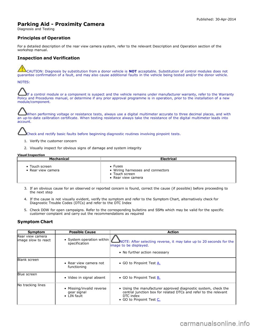
Parking Aid - Proximity Camera
Diagnosis and Testing
Principles of Operation Published: 30-Apr-2014
For a detailed description of the rear view camera system, refer to the relevant Description and Operation section of the
workshop manual.
Inspection and Verification
CAUTION: Diagnosis by substitution from a donor vehicle is NOT acceptable. Substitution of control modules does not
guarantee confirmation of a fault, and may also cause additional faults in the vehicle being tested and/or the donor vehicle.
NOTES:
If a control module or a component is suspect and the vehicle remains under manufacturer warranty, refer to the Warranty
Policy and Procedures manual, or determine if any prior approval programme is in operation, prior to the installation of a new
module/component.
When performing voltage or resistance tests, always use a digital multimeter accurate to three decimal places, and with
an up-to-date calibration certificate. When testing resistance always take the resistance of the digital multimeter leads into
account.
Check and rectify basic faults before beginning diagnostic routines involving pinpoint tests.
1. Verify the customer concern
2. Visually inspect for obvious signs of damage and system integrity
Visual Inspection
Mechanical Electrical
Touch screen
Rear view camera
Fuses
Wiring harnesses and connectors
Touch screen
Rear view camera
3. If an obvious cause for an observed or reported concern is found, correct the cause (if possible) before proceeding to
the next step
4. If the cause is not visually evident, verify the symptom and refer to the Symptom Chart, alternatively check for
Diagnostic Trouble Codes (DTCs) and refer to the DTC Index
5. Check DDW for open campaigns. Refer to the corresponding bulletins and SSMs which may be valid for the specific
customer complaint and carry out the recommendations as required
Symptom Chart
Symptom Possible Cause Action Rear view camera
image slow to react
System operation within
specification
NOTE: After selecting reverse, it may take up to 20 seconds for the
image to be displayed.
No further action necessary Blank screen
Rear view camera not
functioning
GO to Pinpoint Test A. Blue screen
Video in signal absent
GO to Pinpoint Test B. No tracking lines
Missing/invalid reverse
gear signal
LIN fault
Using the manufacturer approved diagnostic system, check the
central junction box for related DTCs and refer to the relevant
DTC index
GO to Pinpoint Test C.
Page 1857 of 3039

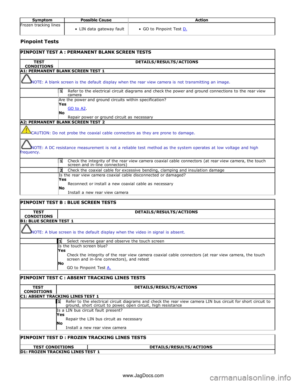
Symptom Possible Cause Action Frozen tracking lines
LIN data gateway fault
GO to Pinpoint Test D. Pinpoint Tests
PINPOINT TEST A : PERMANENT BLANK SCREEN TESTS TEST
CONDITIONS DETAILS/RESULTS/ACTIONS A1: PERMANENT BLANK SCREEN TEST 1
NOTE: A blank screen is the default display when the rear view camera is not transmitting an image. 1 Refer to the electrical circuit diagrams and check the power and ground connections to the rear view camera Are the power and ground circuits within specification? Yes
GO to A2. No
Repair power or ground circuit as necessary A2: PERMANENT BLANK SCREEN TEST 2
CAUTION: Do not probe the coaxial cable connectors as they are prone to damage.
NOTE: A DC resistance measurement is not a reliable test method as the system operates at low voltage and high
frequency. 1 Check the integrity of the rear view camera coaxial cable connectors (at rear view camera, the touch screen and in-line connectors) 2 Check the coaxial cable for excessive bending, clamping and insulation damage Is the rear view camera coaxial cable disconnected or damaged? Yes
Reconnect or install a new coaxial cable as necessary
No
Install a new rear view camera
PINPOINT TEST B : BLUE SCREEN TESTS TEST
CONDITIONS DETAILS/RESULTS/ACTIONS B1: BLUE SCREEN TEST 1
NOTE: A blue screen is the default display when the video in signal is absent. 1 Select reverse gear and observe the touch screen Is the touch screen blue?
Yes
Check the integrity of the rear view camera coaxial cable connectors (at rear view camera, the touch
screen and in-line connectors), and retest
No
GO to Pinpoint Test A.
PINPOINT TEST C : ABSENT TRACKING LINES TESTS TEST
CONDITIONS DETAILS/RESULTS/ACTIONS C1: ABSENT TRACKING LINES TEST 1 1 Refer to the electrical circuit diagrams and check the rear view camera LIN bus circuit for short circuit to ground, short circuit to power, open circuit, high resistance Is a LIN bus circuit fault present? Yes
Repair the LIN bus circuit as necessary
No
Install a new rear view camera
PINPOINT TEST D : FROZEN TRACKING LINES TESTS TEST CONDITIONS DETAILS/RESULTS/ACTIONS D1: FROZEN TRACKING LINES TEST 1 www.JagDocs.com
Page 1858 of 3039

NOTE: The vehicle may take 30 seconds (or 100m) to learn the steering centre position after starting the engine. This is
normal. 1 Start the engine 2 Wait at least 30 seconds 3 Select reverse gear 4 Turn the steering wheel and observe the touch screen Do the tracking lines react to steering input? Yes
No fault present
No
Potential LIN data gateway fault DTC Index
For a list of Diagnostic Trouble Codes (DTCs) that could be logged on this vehicle, please refer to Section 100-00.
Page 1859 of 3039

Parking Aid - Front Inner Parking Aid Sensor
Removal and Installation
Removal Published: 06-Mar-2013
1. Refer to: Front Bumper Cover (501-19 Bumpers, Removal and Installation).
2.
Installation
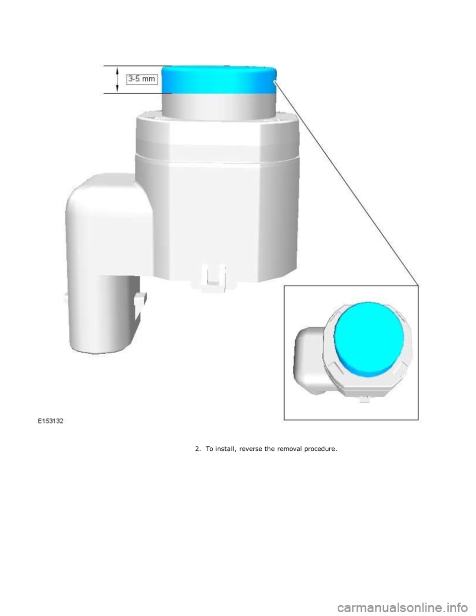
1. CAUTION: If a new sensor is installed, make sure that the area
illustrated is the only area painted. Failure to follow this instruction may
result in the component malfunctioning.
NOTE: On vehicles that are equipped with black or unpainted
bumpers, the sensor(s) do not require painting.
Page 1860 of 3039
