warning JAGUAR XFR 2010 1.G Workshop Manual
[x] Cancel search | Manufacturer: JAGUAR, Model Year: 2010, Model line: XFR, Model: JAGUAR XFR 2010 1.GPages: 3039, PDF Size: 58.49 MB
Page 1664 of 3039
Published: 11-Jul-2014
Climate Control System - General Information - Climate Control System
Diagnosis and Testing
Principles of Operation
For a detailed description of the Climate Control System, refer to the relevant Description and Operation sections in the
Workshop Manual. REFER to:
Air Distribution and Filtering (412-01 Climate Control, Description and Operation), Air Distribution and Filtering (412-01 Climate Control, Description and Operation), Air Distribution and Filtering (412-01 Climate Control, Description and Operation), Heating and Ventilation (412-01 Climate Control, Description and Operation), Heating and Ventilation (412-01 Climate Control, Description and Operation), Heating and Ventilation (412-01 Climate Control, Description and Operation), Air Conditioning (412-01 Climate Control, Description and Operation), Air Conditioning (412-01 Climate Control, Description and Operation), Air Conditioning (412-01 Climate Control, Description and Operation), Control Components (412-01 Climate Control, Description and Operation), Control Components (412-01 Climate Control, Description and Operation), Control Components (412-01 Climate Control, Description and Operation), Electric Booster Heater (412-02 Auxiliary Climate Control, Description and Operation), Electric Booster Heater (412-02 Auxiliary Climate Control, Description and Operation), Electric Booster Heater (412-02 Auxiliary Climate Control, Description and Operation).
Inspection and Verification
WARNING: Servicing must be carried out by personnel familiar with both vehicle system and the charging and testing
equipment. All operations must be carried out in a well ventilated area away from open flame and heat sources.
CAUTION: Diagnosis by substitution from a donor vehicle is NOT acceptable. Substitution of control modules does not
guarantee confirmation of a fault, and may also cause additional faults in the vehicle being tested and/or the donor vehicle.
NOTE: Check and rectify basic faults before beginning diagnostic routines involving pinpoint tests.
1. Verify the customer concern
2. Visually inspect for obvious signs of damage and system integrity
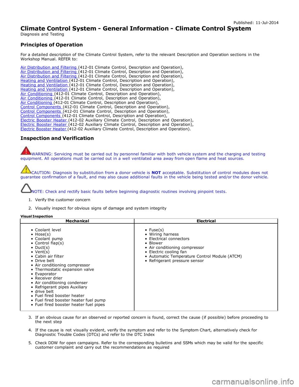
Visual Inspection
Mechanical Electrical
Coolant level
Hose(s)
Coolant pump
Control flap(s)
Duct(s)
Vent(s)
Cabin air filter
Drive belt
Air conditioning compressor
Thermostatic expansion valve
Evaporator
Receiver drier
Air conditioning condenser
Refrigerant pipes Auxiliary
drive belt
Fuel fired booster heater
Fuel fired booster heater fuel pump
Fuel fired booster heater fuel pipes
Fuse(s)
Wiring harness
Electrical connectors
Blower
Air conditioning compressor
Electric cooling fan
Automatic Temperature Control Module (ATCM)
Refrigerant pressure sensor
3. If an obvious cause for an observed or reported concern is found, correct the cause (if possible) before proceeding to
the next step
4. If the cause is not visually evident, verify the symptom and refer to the Symptom Chart, alternatively check for
Diagnostic Trouble Codes (DTCs) and refer to the DTC Index
5. Check DDW for open campaigns. Refer to the corresponding bulletins and SSMs which may be valid for the specific
customer complaint and carry out the recommendations as required
Page 1668 of 3039
Published: 11-May-2011
Climate Control System - General Information - Air Conditioning (A/C) System
Recovery, Evacuation and Charging
General Procedures
1. WARNING: Servicing must be carried out by personnel familliar with both
vehicle system and the charging and testing equipment. All operations
must be carried out in a well ventilated area away from open flame and
heat sources.
NOTE: The receiver drier need only be changed under the following
circumstances: There is dirt in the refrigerant circuit ( eg. compressor
seizure ), the system is leaking and refrigerant has been lost to
atmosphere, or the refrigerant circuit has been open more than 24 hours,
due to repair.
Refrigerant recovery.
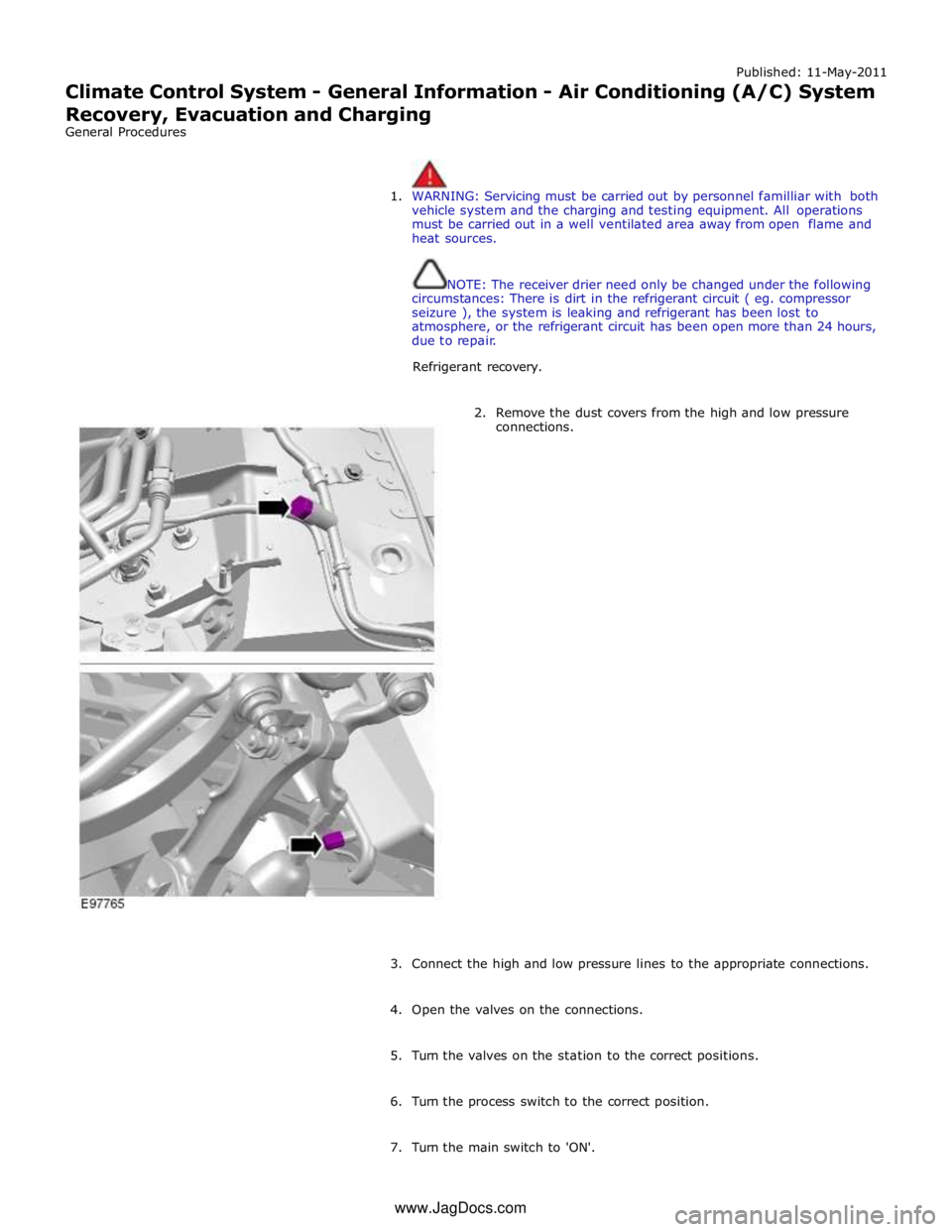
2. Remove the dust covers from the high and low pressure
connections.
3. Connect the high and low pressure lines to the appropriate connections.
4. Open the valves on the connections.
5. Turn the valves on the station to the correct positions.
6. Turn the process switch to the correct position.
7. Turn the main switch to 'ON'. www.JagDocs.com
Page 1669 of 3039
8. WARNING: Refrigerant must always be recycled before re-use to ensure
that the purity of the refrigerantis high enough for safe use in the air
conditioning system. Recycling should always be carried out with
equipment which is design certified by Underwriter Laboratory Inc. for
compliance with SEA J1991. Other equipment may not recycle refrigerant
to the required level of purity. R143a Refrigerant Recover Recycling
Recharging station must not be used with any other type of
refrigerant.Refrigerant R134a from domestic and comercial sources must
not be used in motor vehicles air conditioning systems.
Allow the system to recover the refrigerant from the system.
9. Close the valves on the refrigerant station.
10. Turn the main switch 'OFF'.
11. Close the valves on the connections.
12. Disconnect the high and low pressure connections.
13. Install the dust covers to the connectors.
14. Open the tap at the rear of the station to drain the refrigerant oil.
15. Measure and record the quantity of refrigerant oil recovered from the
system.
16. Close the tap at the rear of the station.
17. Evacuation.
18. Remove the dust covers from the high and low pressure connections.
19. Connect the high and low pressure lines to the appropriate connections.
20. Open the valves on the connections.
21. Turn the valves on the station to the correct positions.
22. Turn the process switch to the correct position.
23. Turn the main switch to 'ON'.
24. Allow the station to evacuate the A/C system.
25. CAUTION: The system must be evacuated immediatley before
recharging commences. Delay between evacuation and recharging is not
permitted
Recharging
26. Close the valves on the refrigerant station.
Page 1671 of 3039
Published: 11-May-2011
Climate Control System - General Information - Air Conditioning (A/C) System
Flushing
General Procedures
1. WARNINGS:
Use extreme care and observe all safety precautions related to the
use of refrigerants. Due to refrigerant hazards, always wear safety
goggles and non-penetrable gloves when working on or flushing air
conditioning (A/C) systems. Failure to follow this instruction may result
in personal injury.
When flushing the A/C system, refer to the manufacturers
equipment instructions for additional information. Failure to do so may
result in system damage or personal injury.
The A/C refrigerant analyzer must be used before the recovery of
any vehicle's A/C refrigerant. Failure to do so puts shop bulk refrigerant
at risk of contamination. If the vehicle A/C refrigerant is contaminated,
refer the customer to return to the repair facility that performed the last
A/C repair. If the customer wishes to pay the additional cost, use the
A/C recovery equipment that is designated for recovering contaminated
A/C refrigerant. All contaminated A/C refrigerant must be disposed of as
hazardous waste. For additional information, refer to the manufacturers
equipment instructions. Failure to follow this instruction may result in
personal injury.
Prior to using the A/C flushing equipment for the first time, follow
the operating instructions. Failure to follow this instruction may result in
personal injury.
CAUTION: Prior to flushing, remove and discard the desiccant sack.
Depending on the equipment used, other A/C components may have to
be removed prior to flushing. For additional information, refer to the
manufacturers equipment instructions before flushing the A/C system.
Recover the refrigerant.
For additional information, refer to Air conditioning (A/C) System Recovery, Evacuation and Charging in this section.
2. Remove the desiccant sack.
For additional information, refer to Section 412-03 Air Conditioning.
3. Flush the system. For additional information, refer to the manufacturers
equipment instructions.
4. Install new refrigerant lines if blocked with debris.
5. Install a new desiccant sack.
For additional information, refer to Section 412-03 Air Conditioning.
6. Add the required amount of oil to the A/C system depending on the
repair procedure.
For additional information, refer to Refrigerant Oil Adding in this section.
7. Evacuate and charge the A/C system.
For additional information, refer to Air conditioning (A/C) System Recovery, Evacuation and Charging in this section.
8. Carry out fluorescent dye leak detection test.
Page 1674 of 3039
Published: 11-May-2011
Climate Control System - General Information - Electronic Leak Detection
General Procedures
1. WARNING: Good ventilation is necessary in the area where A/C leak
testing is to be carried out. If the surrounding air is contaminated with
refrigerant gas, the leak detector will indicate this gas all the time.
Odors from other chemicals such as antifreeze, diesel fuel, disc brake
cleaner, or other cleaning solvents can cause the same problem. A fan,
even in a well ventilated area, is very helpful in removing small traces of
contamination from the air that might affect the leak detector. Failure to
follow this instruction may result in personal injury.
Attach an R-134a manifold gauge set or use a UL-approved
recovery/recycling device such as an R-134a A/C refrigerant center (which
meets SAE Standard J 1991). For additional information, refer to the
manufacturers equipment instructions.
Both gauges should indicate 413-551 kPa (60-80 psi) at 24°C
(75°F) with the engine off.
If little or no pressure is indicated, carry out the air conditioning
(A/C) system recovery, evacuation and charging procedure.
For additional information, refer to Air Conditioning (AC) System Recovery, Evacuation and Charging in this section.
2. Use an R134-a Automatic calibration halogen leak detector to leak test
the refrigerant system. For additional information, refer to the
manufacturers equipment instructions.
3. If a leak is found, carry out the air conditioning (A/C) system recovery
procedure.
For additional information, refer to Air Conditioning (AC) System Recovery, Evacuation and Charging in this section.
Page 1675 of 3039
Published: 11-May-2011
Climate Control System - General Information - Fluorescent Dye Leak Detection
General Procedures
1. WARNING: Eye protection glasses supplied with the ultraviolet (UV)
lamp should be used to protect eyesight from harm.
NOTE: The air conditioning (A/C) system has an R-134a leak trace
dye wafer incorporated into the desiccant bag. The exact location of
leaks can be pinpointed by the bright yellow/green glow of the tracer
dye. Since more than one leak may exist, always inspect each
component. If it is necessary to add dye (due to a severe leakage for
example) use proprietary tracer dye injection equipment.
Check for leaks using ultraviolet (UV) lamp.
2. Check all components, fittings and lines of the A/C system.
3. Carry out the repair. For additional information, refer to Section 412-03 Air Conditioning.
4. After the leak is repaired, remove any traces of leak trace dye with a
general purpose oil solvent.
5. Check the A/C system for correct operation.
6. Verify the repair by operating the system for a short time and inspecting
with the (UV) lamp.
Page 1677 of 3039
Published: 11-May-2011
Climate Control System - General Information - Manifold Gauge Set Connection
General Procedures
1. WARNINGS:
Use extreme care and observe all safety precautions related to the
use of refrigerants. Failure to follow this instruction may result in
personal injury.
For additional information, refer to the manufacturers equipment
instructions. Failure to follow this instruction may result in personal
injury and system damage.
Install the manifold gauge set. For additional information, refer to the
manufacturers equipment instructions.
2. Carry out the repair.
3. Remove the manifold gauge set. For additional information, refer to the
manufacturers equipment instructions.
4. Carry out flourescent dye leak detection test.
For additional information, refer to Flourescent Dye Leak Detection in this section.
5. Check air conditioning (A/C) system for correct operation.
Page 1680 of 3039
Published: 28-Dec-2012
Climate Control System - General Information - Refrigerant System Tests
General Procedures
1. WARNINGS:
Use extreme care and observe all safety precautions related to the
use of refrigerants. Failure to follow this instruction may result in
personal injury.
The A/C refrigerant analyzer must be used before the recovery of
any vehicle's A/C refrigerant. Failure to do so puts shop bulk refrigerant
at risk of contamination. If the vehicle A/C refrigerant is contaminated,
refer the customer to return to the repair facility that carried out the last
A/C repair. If the customer wishes to pay the additional cost, use the A/C
recovery equipment that is designated for recovering contaminated A/C
refrigerant. All contaminated A/C refrigerant must be disposed of as
hazardous waste. For all equipment, follow the equipment manufacturers
procedures and instructions. Failure to follow this instruction may result
in personal injury.
NOTE: Jaguar Land Rover Limited supports the efficient usage,
recovery and recycling of the refrigerant used in passenger car air
conditioners. Jaguar Land Rover Limited recommends the use of
UL-approved recovery/recycling device such as R-134a A/C refrigerant
center (which meets SAE Standard J 1991) during any A/C system repair
and recharge procedure which requires that the system be evacuated.
Use R-134a A/C Refrigerant Centre to evacuate and recover the A/C
system.
Follow the equipment manufactures procedures and instructions
for use of equipment.
Page 1725 of 3039
Climate Control - Climate Control Assembly
Removal and Installation
Removal
NOTES:
Removal steps in this procedure may contain installation details.
RHD illustration shown, LHD is similar. Published: 11-May-2011
1. Refer to: Battery Disconnect and Connect (414-01 Battery, Mounting and Cables, General Procedures).
2. WARNING: Make sure to support the vehicle with axle stands.
Raise and support the vehicle.
3. Refer to: Instrument Panel Console (501-12 Instrument Panel and Console, Removal and Installation).
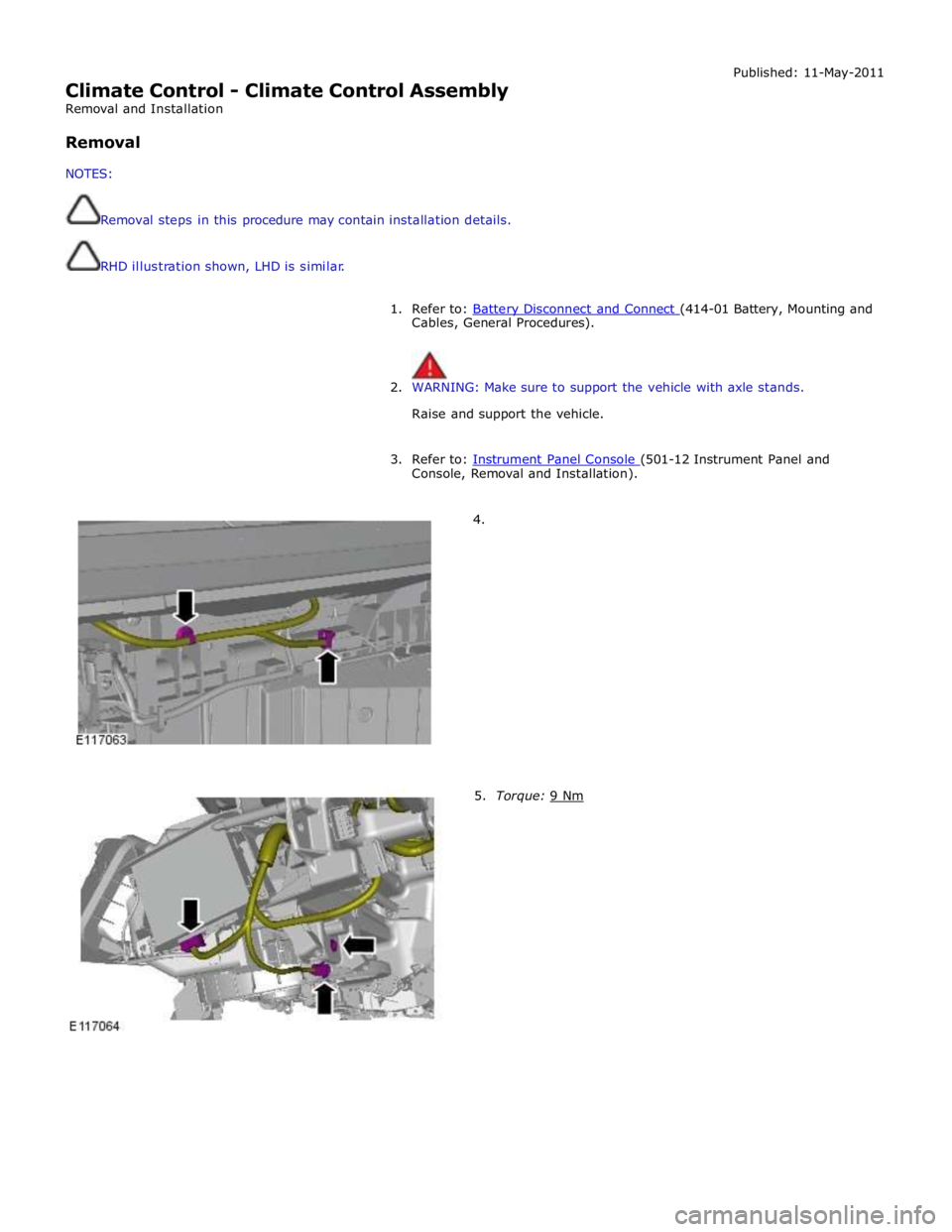
4.
5. Torque: 9 Nm
Page 1736 of 3039
Installation
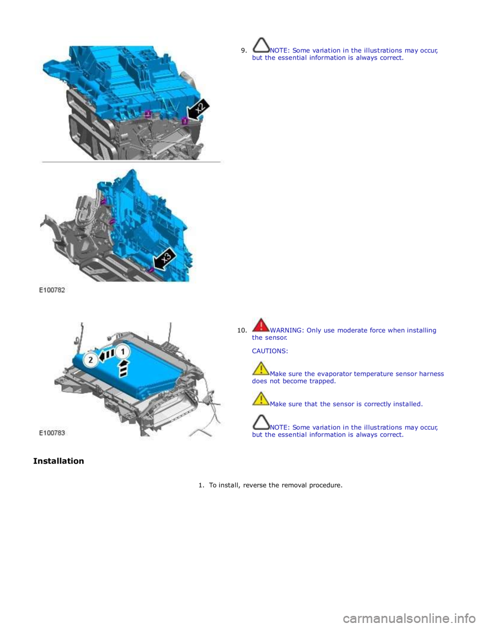
9.
10.
NOTE: Some variation in the illustrations may occur,
but the essential information is always correct.
WARNING: Only use moderate force when installing
the sensor.
CAUTIONS:
Make sure the evaporator temperature sensor harness
does not become trapped.
Make sure that the sensor is correctly installed.
NOTE: Some variation in the illustrations may occur,
but the essential information is always correct.
1. To install, reverse the removal procedure.