fuse JAGUAR XFR 2010 1.G Owner's Manual
[x] Cancel search | Manufacturer: JAGUAR, Model Year: 2010, Model line: XFR, Model: JAGUAR XFR 2010 1.GPages: 3039, PDF Size: 58.49 MB
Page 653 of 3039
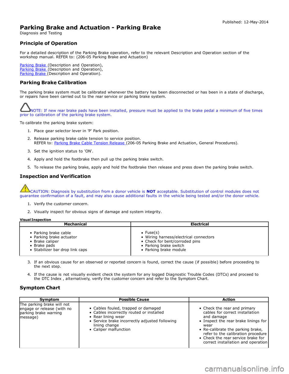
Parking Brake and Actuation - Parking Brake
Diagnosis and Testing
Principle of Operation Published: 12-May-2014
For a detailed description of the Parking Brake operation, refer to the relevant Description and Operation section of the
workshop manual. REFER to: (206-05 Parking Brake and Actuation)
Parking Brake (Description and Operation), Parking Brake (Description and Operation), Parking Brake (Description and Operation).
Parking Brake Calibration
The parking brake system must be calibrated whenever the battery has been disconnected or has been in a state of discharge,
or repairs have been carried out to the rear service or parking brake system.
NOTE: If new rear brake pads have been installed, pressure must be applied to the brake pedal a minimum of five times
prior to calibration of the parking brake system.
To calibrate the parking brake system:
1. Place gear selector lever in 'P' Park position.
2. Release parking brake cable tension to service position.
REFER to: Parking Brake Cable Tension Release (206-05 Parking Brake and Actuation, General Procedures).
3. Set the ignition status to 'ON'.
4. Apply and hold the footbrake then pull up the parking brake switch.
5. To release the parking brake, apply and hold the footbrake then release and press down the parking brake switch.
Inspection and Verification
CAUTION: Diagnosis by substitution from a donor vehicle is NOT acceptable. Substitution of control modules does not
guarantee confirmation of a fault, and may also cause additional faults in the vehicle being tested and/or the donor vehicle.
1. Verify the customer concern.
2. Visually inspect for obvious signs of damage and system integrity.
Visual Inspection
Mechanical Electrical
Parking brake cable
Parking brake actuator
Brake caliper
Brake pads
Stabilizer bar drop link caps
Fuse(s)
Wiring harness/electrical connectors
Check for bent/corroded pins
Parking brake switch
Parking brake module
3. If an obvious cause for an observed or reported concern is found, correct the cause (if possible) before proceeding to
the next step.
4. If the cause is not visually evident check the system for any logged Diagnostic Trouble Codes (DTCs) and proceed to
the DTC Index , alternatively, verify the customer concern and refer to the Symptom Chart.
Symptom Chart
Symptom Possible Cause Action The parking brake will not
engage or release (with no
parking brake warning
message)
Cables fouled, trapped or damaged
Cables incorrectly routed or installed
Rear lining wear
Service brake incorrectly adjusted following
lining change
Caliper malfunction
Check the rear and primary
cables for correct installation
and damage
Inspect the rear brake linings for
wear
Re-calibrate the parking brake,
refer to the calibration procedure
Check the rear service brake for
correct installation and operation
Page 654 of 3039
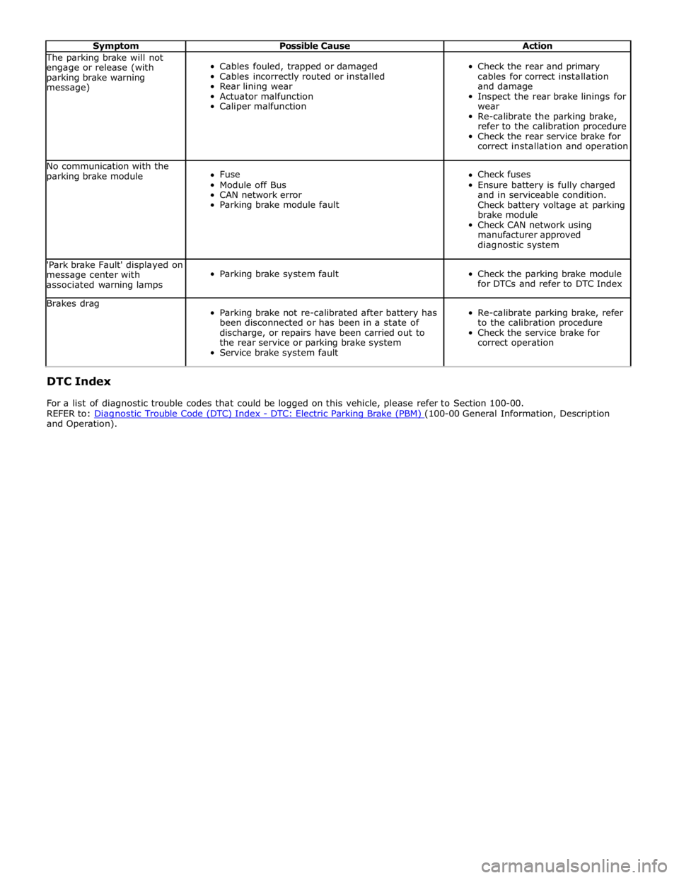
Symptom Possible Cause Action The parking brake will not
engage or release (with
parking brake warning
message)
Cables fouled, trapped or damaged
Cables incorrectly routed or installed
Rear lining wear
Actuator malfunction
Caliper malfunction
Check the rear and primary
cables for correct installation
and damage
Inspect the rear brake linings for
wear
Re-calibrate the parking brake,
refer to the calibration procedure
Check the rear service brake for
correct installation and operation No communication with the
parking brake module
Fuse
Module off Bus
CAN network error
Parking brake module fault
Check fuses
Ensure battery is fully charged
and in serviceable condition.
Check battery voltage at parking
brake module
Check CAN network using
manufacturer approved
diagnostic system 'Park brake Fault' displayed on
message center with
associated warning lamps
Parking brake system fault
Check the parking brake module
for DTCs and refer to DTC Index Brakes drag
Parking brake not re-calibrated after battery has
been disconnected or has been in a state of
discharge, or repairs have been carried out to
the rear service or parking brake system
Service brake system fault
Re-calibrate parking brake, refer
to the calibration procedure
Check the service brake for
correct operation DTC Index
For a list of diagnostic trouble codes that could be logged on this vehicle, please refer to Section 100-00.
REFER to: Diagnostic Trouble Code (DTC) Index - DTC: Electric Parking Brake (PBM) (100-00 General Information, Description and Operation).
Page 680 of 3039

6. Release the fuse box.
7. Remove the brake master cylinder.
Installation
1. To install, reverse the removal procedure.
Install new O-ring seals. www.JagDocs.com
Page 693 of 3039
Published: 11-May-2011
Anti-Lock Control - Stability Assist - Anti-Lock Control - Stability Assist - System Operation and Component Description
Description and Operation
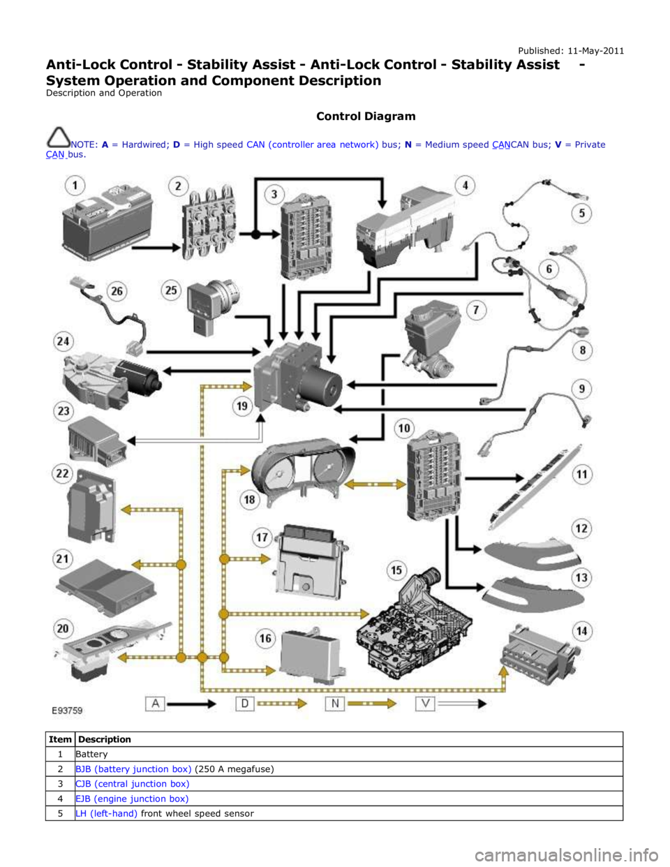
Control Diagram
NOTE: A = Hardwired; D = High speed CAN (controller area network) bus; N = Medium speed CANCAN bus; V = Private CAN bus.
Item Description 1 Battery 2 BJB (battery junction box) (250 A megafuse) 3 CJB (central junction box) 4 EJB (engine junction box) 5 LH (left-hand) front wheel speed sensor
Page 703 of 3039
Published: 09-Jul-2014
Anti-Lock Control - Stability Assist - Anti-Lock Control - Stability Assist
Diagnosis and Testing
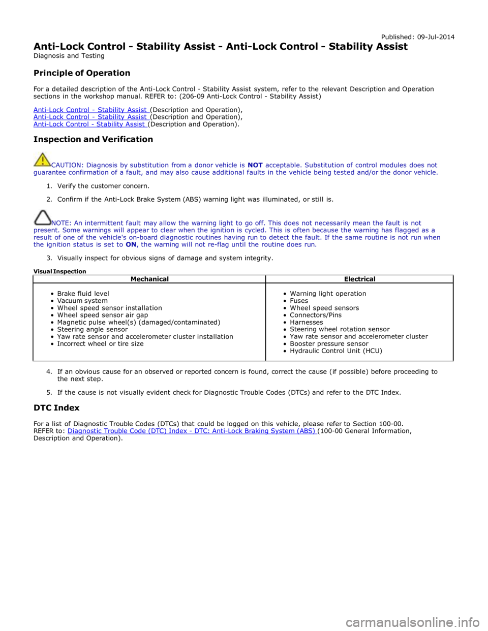
Principle of Operation
For a detailed description of the Anti-Lock Control - Stability Assist system, refer to the relevant Description and Operation
sections in the workshop manual. REFER to: (206-09 Anti-Lock Control - Stability Assist)
Anti-Lock Control - Stability Assist (Description and Operation), Anti-Lock Control - Stability Assist (Description and Operation), Anti-Lock Control - Stability Assist (Description and Operation).
Inspection and Verification
CAUTION: Diagnosis by substitution from a donor vehicle is NOT acceptable. Substitution of control modules does not
guarantee confirmation of a fault, and may also cause additional faults in the vehicle being tested and/or the donor vehicle.
1. Verify the customer concern.
2. Confirm if the Anti-Lock Brake System (ABS) warning light was illuminated, or still is.
NOTE: An intermittent fault may allow the warning light to go off. This does not necessarily mean the fault is not
present. Some warnings will appear to clear when the ignition is cycled. This is often because the warning has flagged as a
result of one of the vehicle's on-board diagnostic routines having run to detect the fault. If the same routine is not run when
the ignition status is set to ON, the warning will not re-flag until the routine does run.
3. Visually inspect for obvious signs of damage and system integrity.
Visual Inspection
Mechanical Electrical
Brake fluid level
Vacuum system
Wheel speed sensor installation
Wheel speed sensor air gap
Magnetic pulse wheel(s) (damaged/contaminated)
Steering angle sensor
Yaw rate sensor and accelerometer cluster installation
Incorrect wheel or tire size
Warning light operation
Fuses
Wheel speed sensors
Connectors/Pins
Harnesses
Steering wheel rotation sensor
Yaw rate sensor and accelerometer cluster
Booster pressure sensor
Hydraulic Control Unit (HCU)
4. If an obvious cause for an observed or reported concern is found, correct the cause (if possible) before proceeding to
the next step.
5. If the cause is not visually evident check for Diagnostic Trouble Codes (DTCs) and refer to the DTC Index.
DTC Index
For a list of Diagnostic Trouble Codes (DTCs) that could be logged on this vehicle, please refer to Section 100-00.
REFER to: Diagnostic Trouble Code (DTC) Index - DTC: Anti-Lock Braking System (ABS) (100-00 General Information, Description and Operation).
Page 718 of 3039
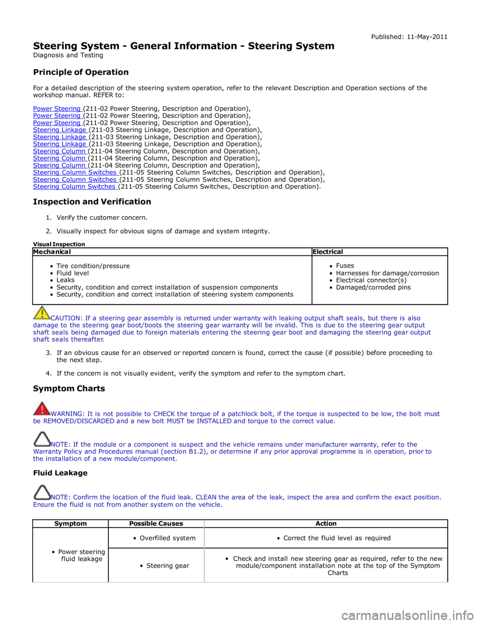
Steering System - General Information - Steering System
Diagnosis and Testing
Principle of Operation Published: 11-May-2011
For a detailed description of the steering system operation, refer to the relevant Description and Operation sections of the
workshop manual. REFER to:
Power Steering (211-02 Power Steering, Description and Operation), Power Steering (211-02 Power Steering, Description and Operation), Power Steering (211-02 Power Steering, Description and Operation), Steering Linkage (211-03 Steering Linkage, Description and Operation), Steering Linkage (211-03 Steering Linkage, Description and Operation), Steering Linkage (211-03 Steering Linkage, Description and Operation), Steering Column (211-04 Steering Column, Description and Operation), Steering Column (211-04 Steering Column, Description and Operation), Steering Column (211-04 Steering Column, Description and Operation), Steering Column Switches (211-05 Steering Column Switches, Description and Operation), Steering Column Switches (211-05 Steering Column Switches, Description and Operation), Steering Column Switches (211-05 Steering Column Switches, Description and Operation).
Inspection and Verification
1. Verify the customer concern.
2. Visually inspect for obvious signs of damage and system integrity.
Visual Inspection
Mechanical Electrical
Tire condition/pressure
Fluid level
Leaks
Security, condition and correct installation of suspension components
Security, condition and correct installation of steering system components
Fuses
Harnesses for damage/corrosion
Electrical connector(s)
Damaged/corroded pins
CAUTION: If a steering gear assembly is returned under warranty with leaking output shaft seals, but there is also
damage to the steering gear boot/boots the steering gear warranty will be invalid. This is due to the steering gear output
shaft seals being damaged due to foreign materials entering the steering gear boot and damaging the steering gear output
shaft seals thereafter.
3. If an obvious cause for an observed or reported concern is found, correct the cause (if possible) before proceeding to
the next step.
4. If the concern is not visually evident, verify the symptom and refer to the symptom chart.
Symptom Charts
WARNING: It is not possible to CHECK the torque of a patchlock bolt, if the torque is suspected to be low, the bolt must
be REMOVED/DISCARDED and a new bolt MUST be INSTALLED and torque to the correct value.
NOTE: If the module or a component is suspect and the vehicle remains under manufacturer warranty, refer to the
Warranty Policy and Procedures manual (section B1.2), or determine if any prior approval programme is in operation, prior to
the installation of a new module/component.
Fluid Leakage
NOTE: Confirm the location of the fluid leak. CLEAN the area of the leak, inspect the area and confirm the exact position.
Ensure the fluid is not from another system on the vehicle.
Symptom Possible Causes Action
Power steering
fluid leakage
Overfilled system
Correct the fluid level as required
Steering gear
Check and install new steering gear as required, refer to the new
module/component installation note at the top of the Symptom
Charts
Page 720 of 3039
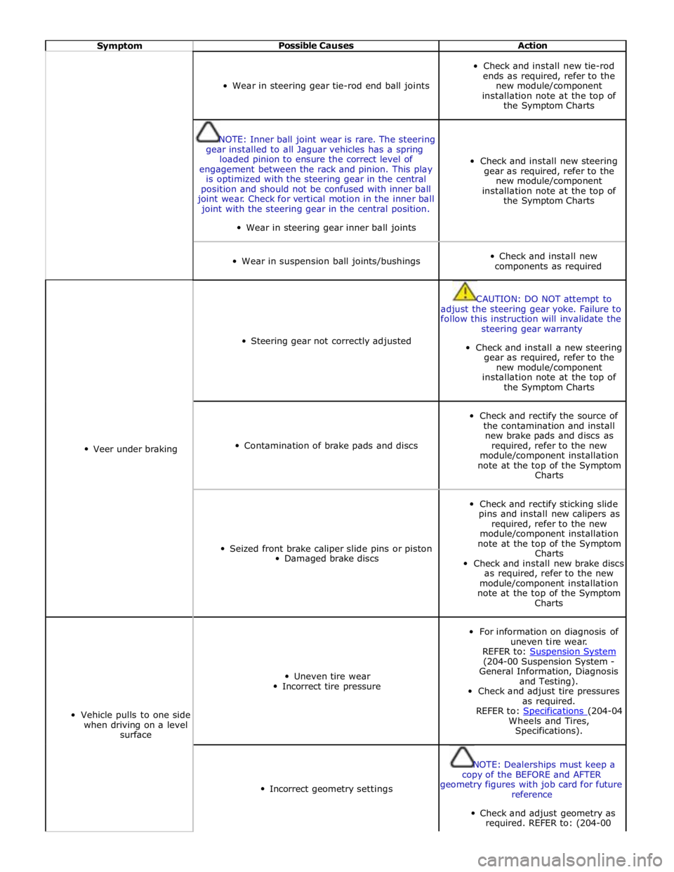
Symptom Possible Causes Action
Wear in steering gear tie-rod end ball joints
Check and install new tie-rod
ends as required, refer to the
new module/component
installation note at the top of
the Symptom Charts
NOTE: Inner ball joint wear is rare. The steering
gear installed to all Jaguar vehicles has a spring
loaded pinion to ensure the correct level of
engagement between the rack and pinion. This play
is optimized with the steering gear in the central
position and should not be confused with inner ball
joint wear. Check for vertical motion in the inner ball
joint with the steering gear in the central position.
Wear in steering gear inner ball joints
Check and install new steering
gear as required, refer to the
new module/component
installation note at the top of
the Symptom Charts
Wear in suspension ball joints/bushings
Check and install new
components as required
Veer under braking
Steering gear not correctly adjusted
CAUTION: DO NOT attempt to
adjust the steering gear yoke. Failure to
follow this instruction will invalidate the
steering gear warranty
Check and install a new steering
gear as required, refer to the
new module/component
installation note at the top of
the Symptom Charts
Contamination of brake pads and discs
Check and rectify the source of
the contamination and install
new brake pads and discs as
required, refer to the new
module/component installation
note at the top of the Symptom
Charts
Seized front brake caliper slide pins or piston
Damaged brake discs
Check and rectify sticking slide
pins and install new calipers as
required, refer to the new
module/component installation
note at the top of the Symptom
Charts
Check and install new brake discs
as required, refer to the new
module/component installation
note at the top of the Symptom
Charts
Vehicle pulls to one side
when driving on a level
surface
Uneven tire wear
Incorrect tire pressure
For information on diagnosis of
uneven tire wear.
REFER to: Suspension System (204-00 Suspension System -
General Information, Diagnosis
and Testing).
Check and adjust tire pressures
as required.
REFER to: Specifications (204-04 Wheels and Tires,
Specifications).
Incorrect geometry settings
NOTE: Dealerships must keep a
copy of the BEFORE and AFTER
geometry figures with job card for future
reference
Check and adjust geometry as
required. REFER to: (204-00
Page 778 of 3039

Published: 20-May-2014
Steering Column - Steering Column - System Operation and Component Description
Description and Operation
Control Diagram
NOTE: A = Hardwired; D = High speed CAN bus; N = Medium speed CAN bus
Item Description 1 Battery 2 BJB (battery junction box) - Megafuse (175A) 3 RJB (rear junction box) 4 Electric steering column lock 5 High Speed CAN (controller area network) bus to other vehicle systems 6 CJB (central junction box)
Page 779 of 3039
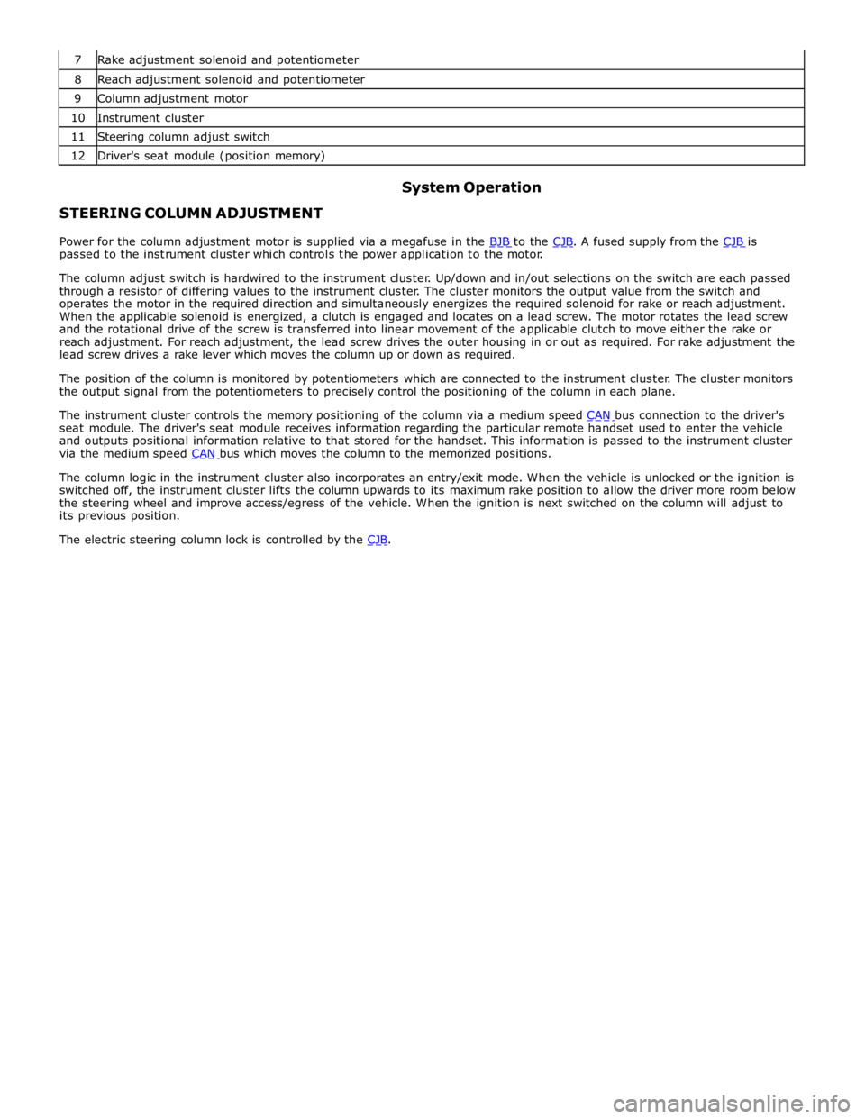
8 Reach adjustment solenoid and potentiometer 9 Column adjustment motor 10 Instrument cluster 11 Steering column adjust switch 12 Driver's seat module (position memory)
STEERING COLUMN ADJUSTMENT System Operation
Power for the column adjustment motor is supplied via a megafuse in the BJB to the CJB. A fused supply from the CJB is passed to the instrument cluster which controls the power application to the motor.
The column adjust switch is hardwired to the instrument cluster. Up/down and in/out selections on the switch are each passed
through a resistor of differing values to the instrument cluster. The cluster monitors the output value from the switch and
operates the motor in the required direction and simultaneously energizes the required solenoid for rake or reach adjustment.
When the applicable solenoid is energized, a clutch is engaged and locates on a lead screw. The motor rotates the lead screw
and the rotational drive of the screw is transferred into linear movement of the applicable clutch to move either the rake or
reach adjustment. For reach adjustment, the lead screw drives the outer housing in or out as required. For rake adjustment the
lead screw drives a rake lever which moves the column up or down as required.
The position of the column is monitored by potentiometers which are connected to the instrument cluster. The cluster monitors
the output signal from the potentiometers to precisely control the positioning of the column in each plane.
The instrument cluster controls the memory positioning of the column via a medium speed CAN bus connection to the driver's seat module. The driver's seat module receives information regarding the particular remote handset used to enter the vehicle
and outputs positional information relative to that stored for the handset. This information is passed to the instrument cluster
via the medium speed CAN bus which moves the column to the memorized positions.
The column logic in the instrument cluster also incorporates an entry/exit mode. When the vehicle is unlocked or the ignition is
switched off, the instrument cluster lifts the column upwards to its maximum rake position to allow the driver more room below
the steering wheel and improve access/egress of the vehicle. When the ignition is next switched on the column will adjust to
its previous position.
The electric steering column lock is controlled by the CJB.
Page 804 of 3039
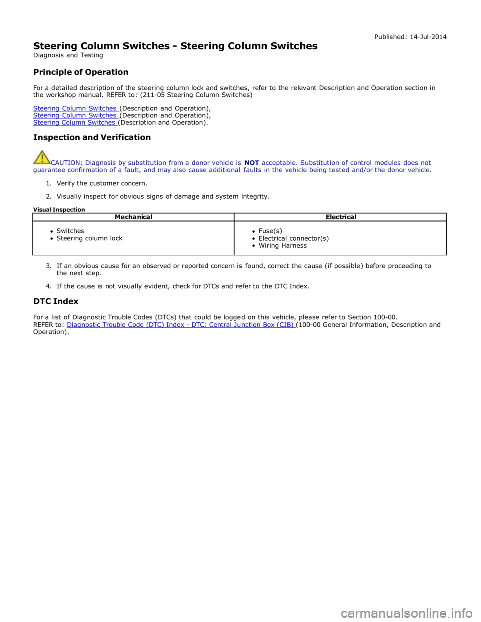
Steering Column Switches - Steering Column Switches
Diagnosis and Testing
Principle of Operation Published: 14-Jul-2014
For a detailed description of the steering column lock and switches, refer to the relevant Description and Operation section in
the workshop manual. REFER to: (211-05 Steering Column Switches)
Steering Column Switches (Description and Operation), Steering Column Switches (Description and Operation), Steering Column Switches (Description and Operation).
Inspection and Verification
CAUTION: Diagnosis by substitution from a donor vehicle is NOT acceptable. Substitution of control modules does not
guarantee confirmation of a fault, and may also cause additional faults in the vehicle being tested and/or the donor vehicle.
1. Verify the customer concern.
2. Visually inspect for obvious signs of damage and system integrity.
Visual Inspection
Mechanical Electrical
Switches
Steering column lock
Fuse(s)
Electrical connector(s)
Wiring Harness
3. If an obvious cause for an observed or reported concern is found, correct the cause (if possible) before proceeding to
the next step.
4. If the cause is not visually evident, check for DTCs and refer to the DTC Index.
DTC Index
For a list of Diagnostic Trouble Codes (DTCs) that could be logged on this vehicle, please refer to Section 100-00.
REFER to: Diagnostic Trouble Code (DTC) Index - DTC: Central Junction Box (CJB) (100-00 General Information, Description and Operation).