fuse JAGUAR XFR 2010 1.G User Guide
[x] Cancel search | Manufacturer: JAGUAR, Model Year: 2010, Model line: XFR, Model: JAGUAR XFR 2010 1.GPages: 3039, PDF Size: 58.49 MB
Page 465 of 3039
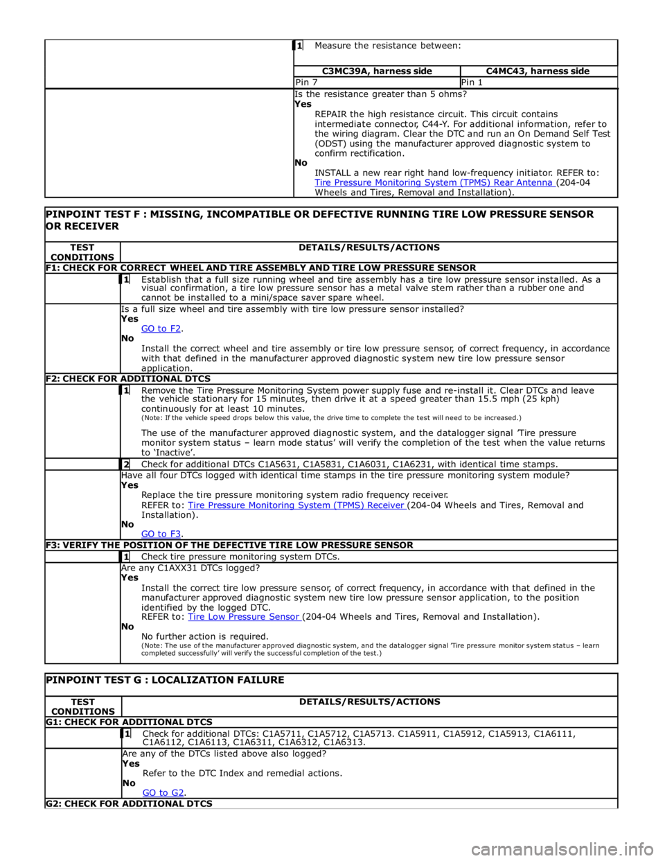
Measure the resistance between: C3MC39A, harness side C4MC43, harness side Pin 7 Pin 1 Is the resistance greater than 5 ohms?
Yes
REPAIR the high resistance circuit. This circuit contains
intermediate connector, C44-Y. For additional information, refer to
the wiring diagram. Clear the DTC and run an On Demand Self Test
(ODST) using the manufacturer approved diagnostic system to
confirm rectification.
No
INSTALL a new rear right hand low-frequency initiator. REFER to:
Tire Pressure Monitoring System (TPMS) Rear Antenna (204-04 Wheels and Tires, Removal and Installation).
PINPOINT TEST F : MISSING, INCOMPATIBLE OR DEFECTIVE RUNNING TIRE LOW PRESSURE SENSOR
OR RECEIVER TEST
CONDITIONS DETAILS/RESULTS/ACTIONS F1: CHECK FOR CORRECT WHEEL AND TIRE ASSEMBLY AND TIRE LOW PRESSURE SENSOR 1 Establish that a full size running wheel and tire assembly has a tire low pressure sensor installed. As a visual confirmation, a tire low pressure sensor has a metal valve stem rather than a rubber one and
cannot be installed to a mini/space saver spare wheel. Is a full size wheel and tire assembly with tire low pressure sensor installed?
Yes
GO to F2. No
Install the correct wheel and tire assembly or tire low pressure sensor, of correct frequency, in accordance
with that defined in the manufacturer approved diagnostic system new tire low pressure sensor
application. F2: CHECK FOR ADDITIONAL DTCS 1 Remove the Tire Pressure Monitoring System power supply fuse and re-install it. Clear DTCs and leave the vehicle stationary for 15 minutes, then drive it at a speed greater than 15.5 mph (25 kph)
continuously for at least 10 minutes.
(Note: If the vehicle speed drops below this value, the drive time to complete the test will need to be increased.)
The use of the manufacturer approved diagnostic system, and the datalogger signal ’Tire pressure
monitor system status – learn mode status’ will verify the completion of the test when the value returns
to ‘Inactive’. 2 Check for additional DTCs C1A5631, C1A5831, C1A6031, C1A6231, with identical time stamps. Have all four DTCs logged with identical time stamps in the tire pressure monitoring system module?
Yes
Replace the tire pressure monitoring system radio frequency receiver.
REFER to: Tire Pressure Monitoring System (TPMS) Receiver (204-04 Wheels and Tires, Removal and Installation).
No
GO to F3. F3: VERIFY THE POSITION OF THE DEFECTIVE TIRE LOW PRESSURE SENSOR 1 Check tire pressure monitoring system DTCs. Are any C1AXX31 DTCs logged?
Yes
Install the correct tire low pressure sensor, of correct frequency, in accordance with that defined in the
manufacturer approved diagnostic system new tire low pressure sensor application, to the position
identified by the logged DTC.
REFER to: Tire Low Pressure Sensor (204-04 Wheels and Tires, Removal and Installation). No
No further action is required.
(Note: The use of the manufacturer approved diagnostic system, and the datalogger signal ’Tire pressure monitor system status – learn completed successfully’ will verify the successful completion of the test.)
PINPOINT TEST G : LOCALIZATION FAILURE TEST
CONDITIONS DETAILS/RESULTS/ACTIONS G1: CHECK FOR ADDITIONAL DTCS 1 Check for additional DTCs: C1A5711, C1A5712, C1A5713. C1A5911, C1A5912, C1A5913, C1A6111, C1A6112, C1A6113, C1A6311, C1A6312, C1A6313. Are any of the DTCs listed above also logged?
Yes
Refer to the DTC Index and remedial actions.
No
GO to G2. G2: CHECK FOR ADDITIONAL DTCS
Page 468 of 3039
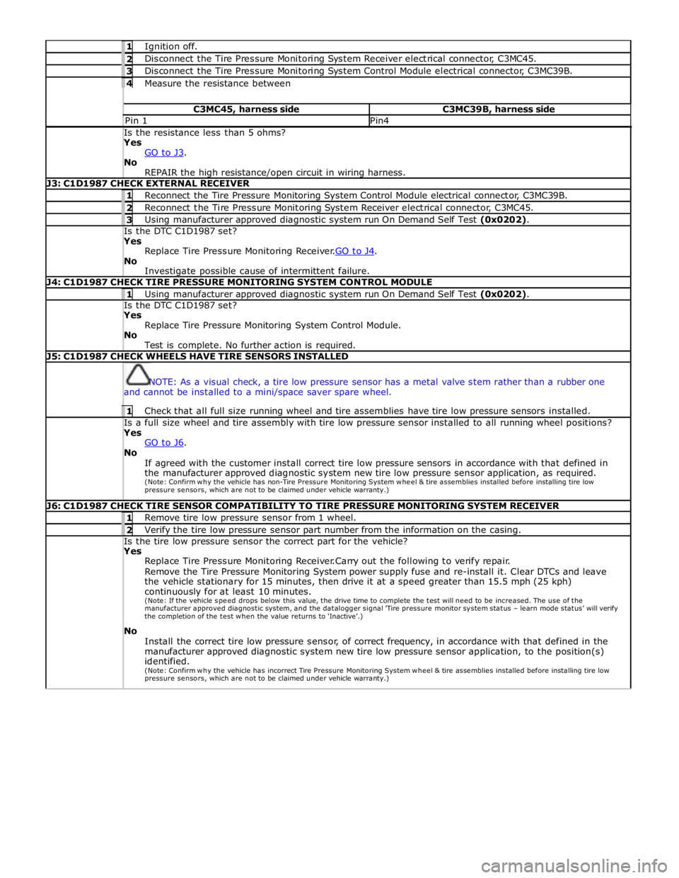
1 Ignition off. 2 Disconnect the Tire Pressure Monitoring System Receiver electrical connector, C3MC45. 3 Disconnect the Tire Pressure Monitoring System Control Module electrical connector, C3MC39B. 4 Measure the resistance between C3MC45, harness side C3MC39B, harness side Pin 1 Pin4 Is the resistance less than 5 ohms? Yes
GO to J3. No
REPAIR the high resistance/open circuit in wiring harness. J3: C1D1987 CHECK EXTERNAL RECEIVER 1 Reconnect the Tire Pressure Monitoring System Control Module electrical connector, C3MC39B. 2 Reconnect the Tire Pressure Monitoring System Receiver electrical connector, C3MC45. 3 Using manufacturer approved diagnostic system run On Demand Self Test (0x0202). Is the DTC C1D1987 set? Yes
Replace Tire Pressure Monitoring Receiver.GO to J4. No
Investigate possible cause of intermittent failure. J4: C1D1987 CHECK TIRE PRESSURE MONITORING SYSTEM CONTROL MODULE 1 Using manufacturer approved diagnostic system run On Demand Self Test (0x0202). Is the DTC C1D1987 set? Yes
Replace Tire Pressure Monitoring System Control Module.
No
Test is complete. No further action is required. J5: C1D1987 CHECK WHEELS HAVE TIRE SENSORS INSTALLED
NOTE: As a visual check, a tire low pressure sensor has a metal valve stem rather than a rubber one
and cannot be installed to a mini/space saver spare wheel. 1 Check that all full size running wheel and tire assemblies have tire low pressure sensors installed. Is a full size wheel and tire assembly with tire low pressure sensor installed to all running wheel positions? Yes
GO to J6. No
If agreed with the customer install correct tire low pressure sensors in accordance with that defined in
the manufacturer approved diagnostic system new tire low pressure sensor application, as required.
(Note: Confirm why the vehicle has non-Tire Pressure Monitoring System w he e l & tire assemblies installed before installing tire low
pressure sensors, which are not to be claimed under vehicle warranty.) J6: C1D1987 CHECK TIRE SENSOR COMPATIBILITY TO TIRE PRESSURE MONITORING SYSTEM RECEIVER 1 Remove tire low pressure sensor from 1 wheel. 2 Verify the tire low pressure sensor part number from the information on the casing. Is the tire low pressure sensor the correct part for the vehicle? Yes
Replace Tire Pressure Monitoring Receiver.Carry out the following to verify repair.
Remove the Tire Pressure Monitoring System power supply fuse and re-install it. Clear DTCs and leave
the vehicle stationary for 15 minutes, then drive it at a speed greater than 15.5 mph (25 kph)
continuously for at least 10 minutes.
(Note: If the vehicle spe e d drops below this value, the drive time to complete the test will need to be increased. The use of the manufacturer approved diagnostic system, and the datalogger signal ’Tire pressure monitor system status – learn mode status’ will verify the completion of the test w he n the value returns to ‘Inactive’.)
No
Install the correct tire low pressure sensor, of correct frequency, in accordance with that defined in the
manufacturer approved diagnostic system new tire low pressure sensor application, to the position(s)
identified.
(Note: Confirm why the vehicle has incorrect Tire Pressure Monitoring System w he e l & tire assemblies installed before installing tire low
pressure sensors, which are not to be claimed under vehicle warranty.)
Page 482 of 3039
Published: 11-May-2011
Vehicle Dynamic Suspension - Vehicle Dynamic Suspension V8 5.0L Petrol/V8 S/C 5.0L Petrol - System Operation and Component Description
Description and Operation
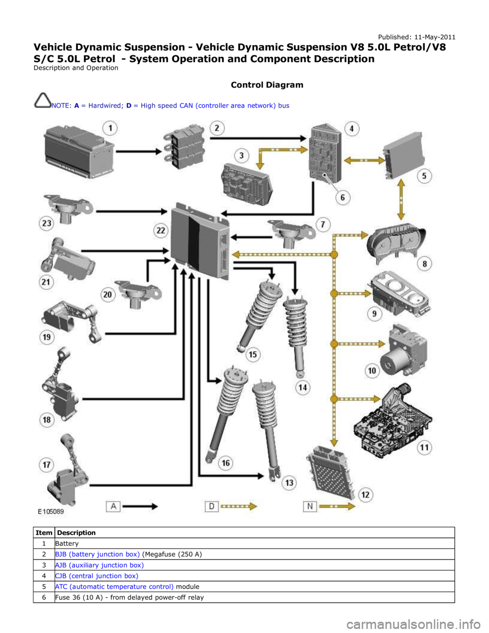
Control Diagram
NOTE: A = Hardwired; D = High speed CAN (controller area network) bus
Item Description 1 Battery 2 BJB (battery junction box) (Megafuse (250 A) 3 AJB (auxiliary junction box) 4 CJB (central junction box) 5 ATC (automatic temperature control) module 6 Fuse 36 (10 A) - from delayed power-off relay
Page 484 of 3039
each damper to the appropriate level to maintain a flat and level body.
Roll Rate Control – Uses CAN inputs. Predicts vehicle roll rate due to driver steering inputs 100 times a second and increases damping to reduce roll rate.
Pitch Rate Control – Uses CAN inputs. Predicts vehicle pitch rate due to driver throttle and braking inputs 100 times a second and increases damping to reduce pitch rate.
Bump Rebound Control – Uses suspension height sensor and CAN inputs. Monitors the position of the wheel 500 times a second and increases the damping rate as the damper approaches the end of its travel.
Wheel Hop Control – Uses suspension height sensor and CAN inputs. Monitors the position of the wheel 500 times a second and detects when the wheel is at its natural frequency and increases the dampingto reduce vertical wheel
motion.
Under normal road conditions when the vehicle is stationary with the engine running, the dampers are set to the firm condition
to reduce power consumption.
The adaptive damping module receives its power supply via a relay and fuse in the CJB. The relay remains energized for a period of time after the ignition is off. This allows the adaptive damping module to record and store any DTC (diagnostic
trouble code) relating to adaptive dynamics system faults.
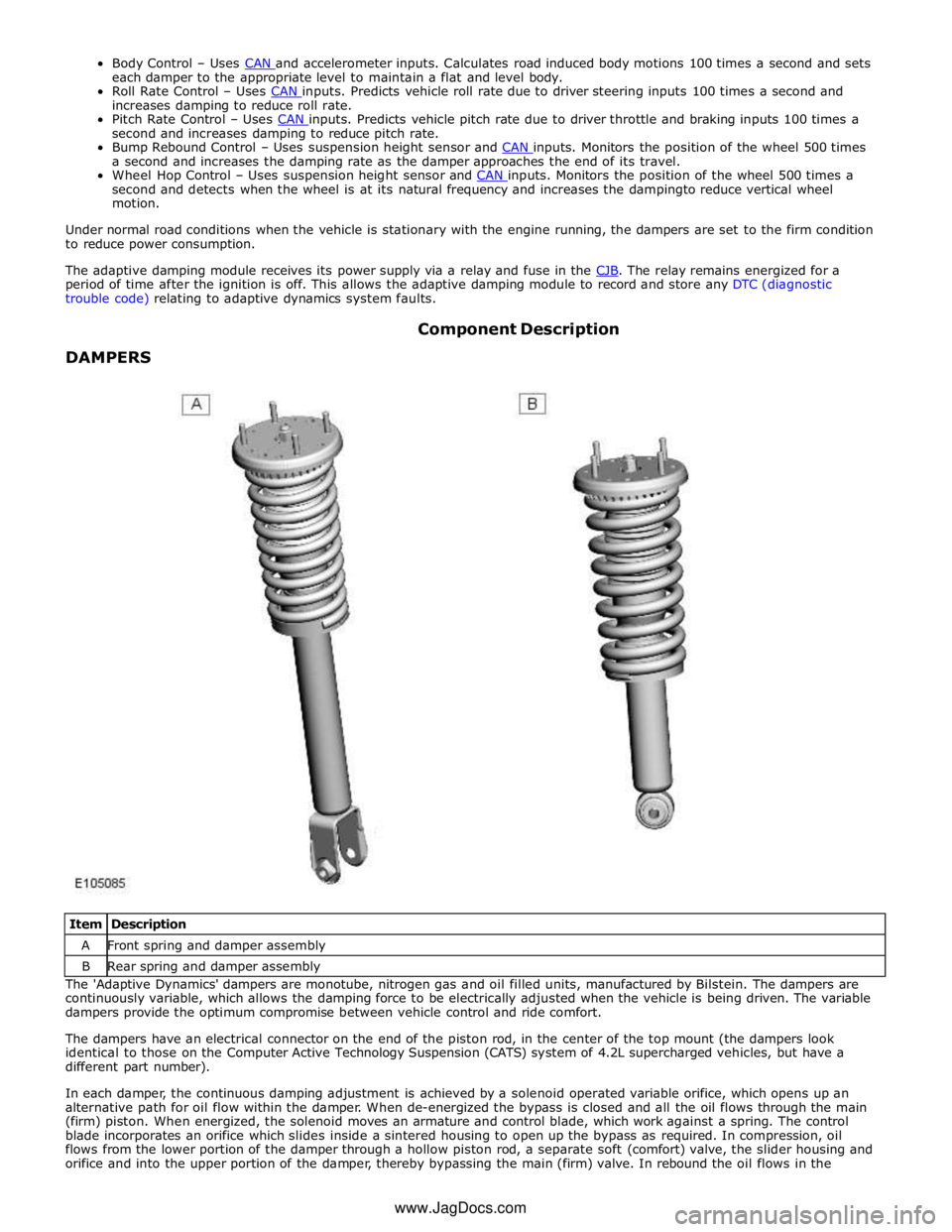
DAMPERS Component Description
Item Description A Front spring and damper assembly B Rear spring and damper assembly The 'Adaptive Dynamics' dampers are monotube, nitrogen gas and oil filled units, manufactured by Bilstein. The dampers are
continuously variable, which allows the damping force to be electrically adjusted when the vehicle is being driven. The variable
dampers provide the optimum compromise between vehicle control and ride comfort.
The dampers have an electrical connector on the end of the piston rod, in the center of the top mount (the dampers look
identical to those on the Computer Active Technology Suspension (CATS) system of 4.2L supercharged vehicles, but have a
different part number).
In each damper, the continuous damping adjustment is achieved by a solenoid operated variable orifice, which opens up an
alternative path for oil flow within the damper. When de-energized the bypass is closed and all the oil flows through the main
(firm) piston. When energized, the solenoid moves an armature and control blade, which work against a spring. The control
blade incorporates an orifice which slides inside a sintered housing to open up the bypass as required. In compression, oil
flows from the lower portion of the damper through a hollow piston rod, a separate soft (comfort) valve, the slider housing and
orifice and into the upper portion of the damper, thereby bypassing the main (firm) valve. In rebound the oil flows in the www.JagDocs.com
Page 488 of 3039

Vehicle Dynamic Suspension - Vehicle Dynamic Suspension
Diagnosis and Testing
Principle of Operation Published: 09-Jul-2014
For a detailed description of the adaptive damping system operation, refer to the relevant Description and Operation section of
the workshop manual. REFER to: (204-05 Vehicle Dynamic Suspension)
Vehicle Dynamic Suspension - V8 5.0L Petrol/V8 S/C 5.0L Petrol (Description and Operation),
Inspection and Verification
1. Verify the customer concern.
2. Visually inspect for obvious signs of damage and system integrity.
Visual Inspection
Mechanical Electrical
Coil spring(s)
Shock absorber(s)
Accelerometer(s) installation
Height sensor(s) installation
Fuse(s)
Wiring harness/electrical connectors
Accelerometer(s)
Adaptive Damping Control Module
Height sensor(s)
3. If an obvious cause for an observed or reported concern is found, correct the cause (if possible) before proceeding to
the next step.
4. If the cause is not visually evident, check the system for any logged Diagnostic Trouble Codes (DTCs) and refer to the
DTC index.
DTC Index
For a list of Diagnostic Trouble Codes (DTCs) that could be logged on this vehicle, please refer to Section 100-00.
REFER to: Diagnostic Trouble Code (DTC) Index - DTC: Adaptive Damping Module (SUMB) (100-00 General Information, Description and Operation).
Page 495 of 3039
Published: 11-May-2011
Ride and Handling Optimization - Ride and Handling Optimization - System
Operation and Component Description
Description and Operation
JAGUARDRIVE CONTROL OPERATION
Engine Management System System Operation
The Engine Management System (EMS) varies the accelerator pedal maps to change the amount of torque per percentage of
pedal travel. The EMS can also change the accelerator pedal response to control the allowed torque change relative to the
speed of pedal travel.
Each driving mode uses a combination of operating parameters for each sub-system. Changing between driving modes initiates
a different set of operating characteristics, which will be noticeable to the driver. The driver will notice differences in engine
response when, for example, the accelerator pedal is held in a constant position and the driving mode is changed from Winter
to Dynamic, the driver will notice the torque and engine speed increase. Similarly, if the mode is changed from Normal or
Dynamic to Winter the driver will notice a reduction in torque and engine speed.
NOTE: The change in torque and engine speed can take approximately 30 seconds and care must be taken not to confuse
the JaguarDrive Control system operation with an EMS fault.
Transmission Control
The TCM (transmission control module) changes the shift maps for the JaguarDrive Control mode selected. This changes the
shift points providing early or late upshifts and downshifts. For example, on slippery surfaces in Winter mode the transmission
will select 2nd gear for starting from a standstill on a flat surface to minimize wheel slip.
Anti-lock Braking System Control
The ABS (anti-lock brake system) module controls several vehicle functions and adjusts the operating parameters of these
functions to optimize the selected JaguarDrive Control mode. Traction control uses different slip/acceleration thresholds to
improve traction and vehicle composure. For example, the system sensitivity is increased on slippery surfaces to reduce wheel
spin.
If TracDSC is selected or DSC is switched off, then subsequently the JaguarDrive Control mode is changed, DSC is automatically
switched back on (or to TracDSC for Dynamic mode).
The stability control uses different threshold values for the selected mode, reducing the requirement for the driver to change
the DSC system mode for optimum performance in various driving scenarios.
Incorrect Mode Usage
Selection of an inappropriate mode is discouraged in the following ways:
The active mode icon is continually displayed in the instrument cluster message center
In any special mode, when the ignition has been in the off position continuously for more than 6 hours, the JaguarDrive
Control system defaults to the special modes off (DSC on).
Selection of an inappropriate mode for the conditions will not endanger the driver or immediately cause damage to the vehicle.
Continued use of an inappropriate mode may reduce the life of some components. The driver may notice a different vehicle
response, with the engine and transmission responses being different than in the special modes off.
Driver Information
The instrument cluster contains a message center, which displays vehicle information to the driver. The message center
contains the JaguarDrive Control mode icons, which display the currently selected mode. If no symbol is displayed, no special
mode is selected and the system is in special modes off.
Any required changes to the subsystems are also passed to the driver in the form of warning illumination in the instrument
cluster or appropriate messages in the message center, DSC off for example.
In Dynamic mode when the transmission is in manual mode, the gear information is displayed in amber when the appropriate
engine speed is reached for optimum sporty change point.
DIAGNOSTICS
JaguarDrive Control relies on the correct functionality of the sub-systems. If one of the sub-systems develops a fault, the
JaguarDrive Control system will not function, even though the fault is not in the JaguarDrive Control system.
The JaguarDrive Selector module and rotary control should only be investigated if there are no apparent faults in any of the
sub-systems. If a fault in a sub-system is subsequently corrected, the JaguarDrive Control system will function normally after
an ignition on and off cycle.
Page 531 of 3039
Published: 11-May-2011
Rear Drive Axle/Differential - Rear Drive Axle and Differential - System
Operation and Component Description
Description and Operation
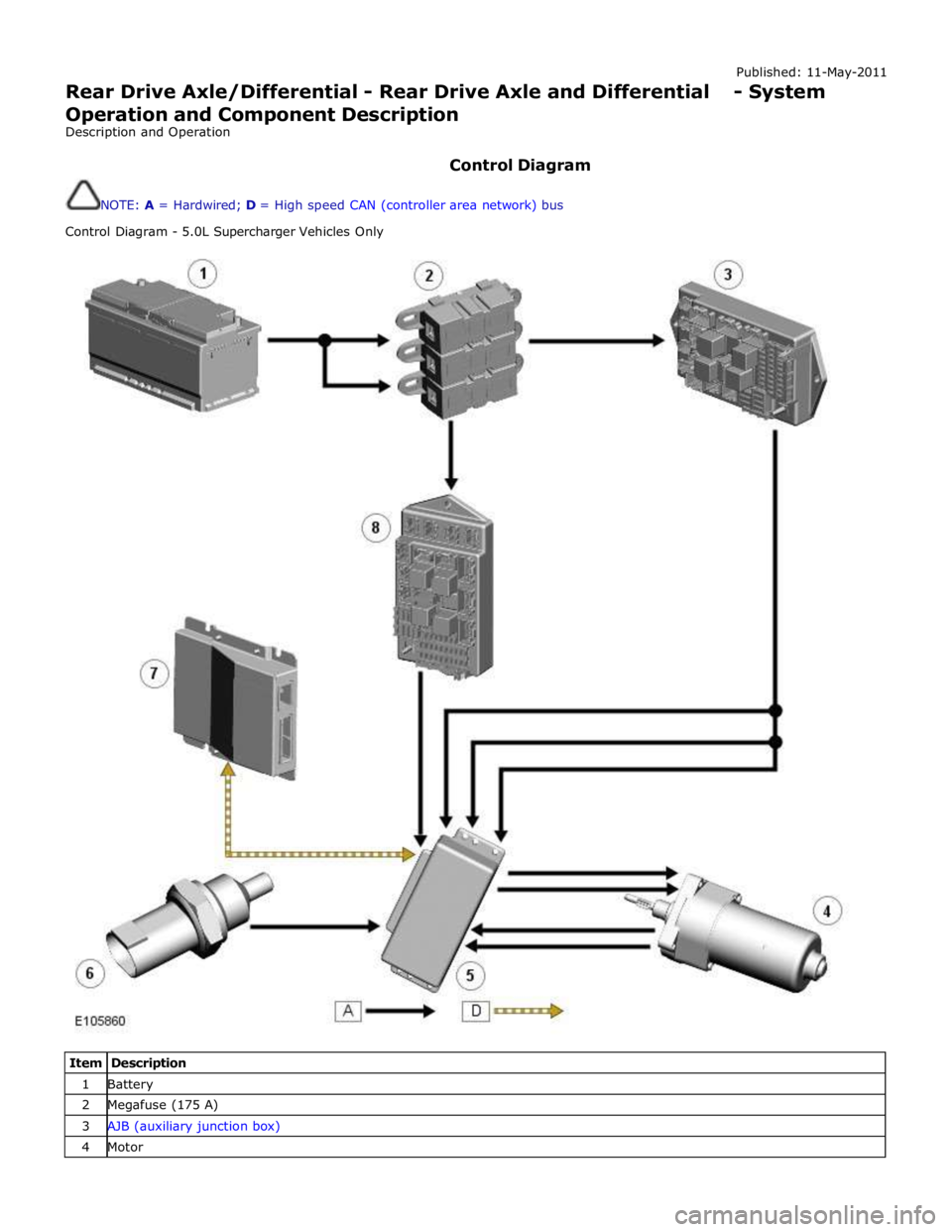
Control Diagram
NOTE: A = Hardwired; D = High speed CAN (controller area network) bus
Control Diagram - 5.0L Supercharger Vehicles Only
Item Description 1 Battery 2 Megafuse (175 A) 3 AJB (auxiliary junction box) 4 Motor
Page 538 of 3039
Rear Drive Axle/Differential - Rear Drive Axle and Differential
Diagnosis and Testing
Principle of Operation Published: 12-May-2014
For a detailed description of the Rear Drive Axle and Differential, refer to the relevant Description and Operation section in the
workshop manual. REFER to: Rear Drive Axle and Differential (205-02 Rear Drive Axle/Differential, Description and Operation).
Inspection and Verification
CAUTION: Diagnosis by substitution from a donor vehicle is NOT acceptable. Substitution of control modules does not
guarantee confirmation of a fault, and may also cause additional faults in the vehicle being tested and/or the donor vehicle.
1. Verify the customer concern.
2. Visually inspect for obvious signs of damage and system integrity.
Mechanical Electrical
Fixings that secure Rear Differential Control Module (Heat path
for Module Heatsink)
Fuses/Relays
Damaged, Loose or Corroded Connector(s)
Damage to Wiring Loom/Incorrect Location,
Stretched or Taught
3. If an obvious cause for an observed or reported concern is found, correct the cause (if possible) before proceeding to
the next step.
4. If the cause is not visually evident, check the system for any logged Diagnostic Trouble Codes (DTCs) and refer to the
DTC index.
DTC Index
For a list of diagnostic trouble codes that could be logged on this vehicle, please refer to Section 100-00. REFER to: Diagnostic Trouble Code (DTC) Index - DTC: Rear Differential Control Module (RDCM) (100-00 General Information, Description and Operation).
Page 609 of 3039

Published: 11-May-2011
Front Disc Brake - TDV6 3.0L Diesel /V8 5.0L Petrol/V8 S/C 5.0L Petrol - Front Disc Brake - System Operation and Component Description
Description and Operation
Control Diagram
NOTE: A = Hardwired
Item Description 1 Battery 2 Megafuse (250 A) 3 Front brake pad wear sensor 4 Rear brake pad wear sensor 5 Instrument cluster 6 CJB (central junction box) 7 Power distribution box
Page 631 of 3039

Published: 11-May-2011
Rear Disc Brake - TDV6 3.0L Diesel /V8 5.0L Petrol/V8 S/C 5.0L Petrol - Rear
Disc Brake - System Operation and Component Description
Description and Operation
Control Diagram
NOTE: A = Hardwired
Item Description 1 Battery 2 Megafuse (250 A) 3 Front brake pad wear sensor 4 Rear brake pad wear sensor 5 Instrument cluster 6 CJB (central junction box) 7Powerdistributionbox