ESP JAGUAR XFR 2010 1.G Repair Manual
[x] Cancel search | Manufacturer: JAGUAR, Model Year: 2010, Model line: XFR, Model: JAGUAR XFR 2010 1.GPages: 3039, PDF Size: 58.49 MB
Page 279 of 3039
Published: 12-May-2014
General Information - Diagnostic Trouble Code (DTC) Index DTC: Telephone
Module (TEL)
Description and Operation
Telephone Module
CAUTION: Diagnosis by substitution from a donor vehicle is NOT acceptable. Substitution of control modules does not
guarantee confirmation of a fault, and may also cause additional faults in the vehicle being tested and/or the donor vehicle.
NOTES:
If a control module or a component is suspect and the vehicle remains under manufacturer warranty, refer to the Warranty
Policy and Procedures manual, or determine if any prior approval programme is in operation, prior to the installation of a new
module/component.
Generic scan tools may not read the codes listed, or may read only 5-digit codes. Match the 5 digits from the scan tool to
the first 5 digits of the 7-digit code listed to identify the fault (the last 2 digits give extra information read by the
manufacturer-approved diagnostic system).
When performing voltage or resistance tests, always use a digital multimeter accurate to three decimal places, and with
an up-to-date calibration certificate. When testing resistance always take the resistance of the digital multimeter leads into
account.
Check and rectify basic faults before beginning diagnostic routines involving pinpoint tests.
Inspect connectors for signs of water ingress, and pins for damage and/or corrosion.
If DTCs are recorded and, after performing the pinpoint tests, a fault is not present, an intermittent concern may be the
cause. Always check for loose connections and corroded terminals.
Check DDW for open campaigns. Refer to the corresponding bulletins and SSMs which may be valid for the specific
customer complaint and carry out the recommendations as required.
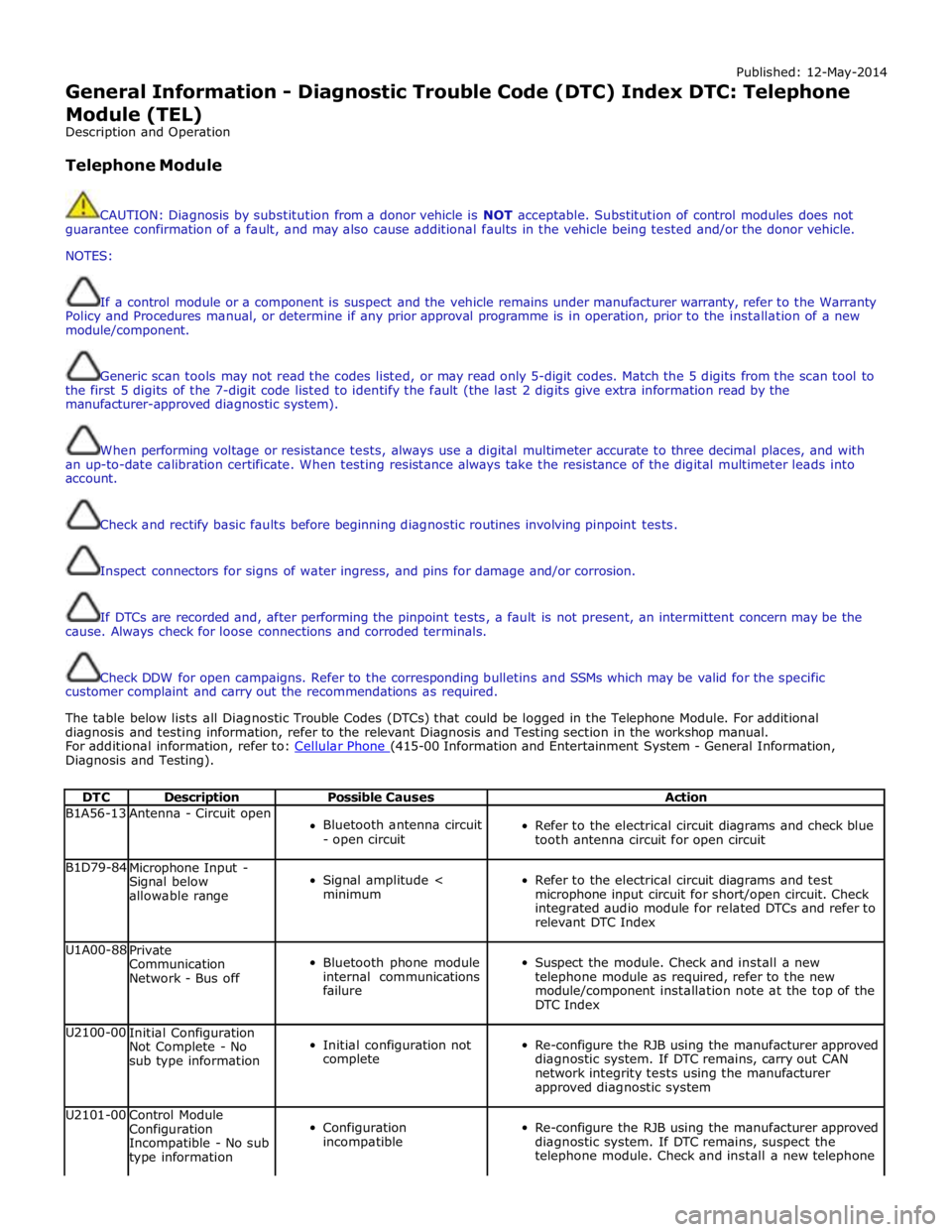
The table below lists all Diagnostic Trouble Codes (DTCs) that could be logged in the Telephone Module. For additional
diagnosis and testing information, refer to the relevant Diagnosis and Testing section in the workshop manual.
For additional information, refer to: Cellular Phone (415-00 Information and Entertainment System - General Information, Diagnosis and Testing).
DTC Description Possible Causes Action B1A56-13 Antenna - Circuit open
Bluetooth antenna circuit
- open circuit
Refer to the electrical circuit diagrams and check blue
tooth antenna circuit for open circuit B1D79-84
Microphone Input -
Signal below
allowable range
Signal amplitude <
minimum
Refer to the electrical circuit diagrams and test
microphone input circuit for short/open circuit. Check
integrated audio module for related DTCs and refer to
relevant DTC Index U1A00-88
Private
Communication
Network - Bus off
Bluetooth phone module
internal communications
failure
Suspect the module. Check and install a new
telephone module as required, refer to the new
module/component installation note at the top of the
DTC Index U2100-00
Initial Configuration
Not Complete - No
sub type information
Initial configuration not
complete
Re-configure the RJB using the manufacturer approved
diagnostic system. If DTC remains, carry out CAN
network integrity tests using the manufacturer
approved diagnostic system U2101-00
Control Module
Configuration
Incompatible - No sub
type information
Configuration
incompatible
Re-configure the RJB using the manufacturer approved
diagnostic system. If DTC remains, suspect the
telephone module. Check and install a new telephone
Page 298 of 3039

Published: 11-May-2011
Noise, Vibration and Harshness - Noise, Vibration and Harshness (NVH)
Description and Operation
Noise, vibration and harshness (NVH) is becoming more important as vehicles become more sophisticated and passenger
comfort levels increase. This section is designed to aid in the diagnosis, testing and repair of NVH concerns.
Noise is defined as sounds not associated with the operation of passenger compartment equipment that interface with
customer satisfaction.
Vibration is defined as impulses felt by the customer that are not caused by road surface changes.
Harshness is a ride quality issue where the customer feels that the vehicle response to the road surface is sharply
transmitted to the customer.
Diagnostic Theory
Diagnosis is more than just following a series of interrelated steps in order to find the solution to the specific condition. It is a
way of looking at systems that are not functioning the way they should and finding out why. Also it is knowing how the system
should work and whether it is working correctly.
There are basic rules for diagnosis. If these rules are followed, the cause of the condition is usually found the first time
through the system.
Know the System
Know how the parts go together.
Know how the system operates as well as its limits and what happens when the system goes wrong.
Sometimes this means checking the system against one that is known to be working correctly.
Know the History of the System
A clue in any one of these areas may save time:
How old or new is the system?
What kind of treatment has it had?
Has it been repaired in the past in such a manner that might relate to the present condition?
What is the repair history?
Know the History of the Condition
Did it start suddenly or appear gradually?
Was it related to some other occurrence such as a collision or previous part renewal?
Know how the condition made itself known; it may be an important clue to the cause.
Know the Probability of Certain Conditions Developing
Look for the simple rather than the complex.
For example:
- Electrical conditions usually occur at connections rather than components.
- An engine no-start is more likely to be caused by a loose wire or small adjustment rather than a sheared-off
camshaft.
Know the difference between impossible and improbable. Certain failures in a system can be improbable but still
happen.
New parts are just that, new. It does not mean they are always good functioning parts.
Do Not Cure the Symptom and Leave the Cause
Lowering the pressure in a front tire may correct the condition of a vehicle leaning to one side, but it does not correct the
original condition.
Be Positive the Cause is Found
Double check the findings.
What caused a worn component?
A loose transmission or engine mount could indicate that other mounts are also loose.
Diagnostic Charts
Charts are a simple way of expressing the relationship between basic logic and a physical system of components. They help
discover the cause of a condition in the least time. Diagnostic charts combine many areas of diagnosis into one visual display:
probability of certain things occurring in a system
speed of checking certain components or functions before others
simplicity of carrying out certain tests before others
elimination of checking huge portions of a system by carrying out simple tests
certainty of narrowing down the search to a small portion before carrying out in-depth testing
The fastest way to find a condition is to work with the tools that are available. This means working with proven diagnostic
charts and the correct special equipment for the system.
Page 299 of 3039

Published: 16-Sep-2013
Noise, Vibration and Harshness - Noise, Vibration and Harshness (NVH)
Diagnosis and Testing
Principle of Operation
For a detailed description of Noise, Vibration and Harshness issues, refer to the Description and Operation section of the
workshop manual.
REFER to: Noise, Vibration and Harshness (NVH) (100-04 Noise, Vibration and Harshness, Description and Operation).
Inspection and Verification
1. Verify the customer's concerns by operating the vehicle to duplicate the condition.
2. Visually inspect the vehicle to determine any obvious cause(s) of the concern(s).
3. If the inspection reveals obvious causes that can be readily identified, repair as necessary.
4. If the concern(s) remains after the inspection, determine the symptom(s) and refer to the Symptom Chart.
How To Use This Diagnostic Procedure Section
Noise, vibration and harshness (NVH) concerns have become more important as vehicles have become more sensitive to
these vibrations. This section is designed as an aid to identifying these situations
The section provides diagnostic procedures based on symptoms. If the condition occurs at high speed, for instance, the
most likely place to start is under High Speed Shake
The road test procedure will tell how to sort the conditions into categories and how to tell a vibration from a shake
A series of Road Test Quick Checks is provided to make sure that a cause is either pinpointed or eliminated
Name the condition, proceed to the appropriate section and locate the correct diagnosis. When the condition is
identified, the job is partly done
Follow the diagnostic procedure as outlined
Quick Checks are described within the step, while more involved tests and adjustments are outlined in General
Procedures
Always follow each step exactly and make notes to recall important findings later
Customer Interview
The road test and customer interview (if available) provide information that will help identify the concerns and will provide
direction to the correct starting point for diagnosis.
Identify the Condition
NVH problems usually occur in a number of areas:
tires
engine accessories
suspension
driveline
air leakage (wind noise)
squeaks and rattles
heating ventilation and air conditioning (HVAC)
electrical (e.g. motor noise)
transmission
engine
It is important, therefore, that an NVH concern be isolated into its specific area(s) as soon as possible. The easiest and
quickest way to do this is to carry out the Road Test as outlined.
Noise Diagnostic Procedure
Non-Axle Noise
The five most important sources of non-axle noise are exhaust, tires, roof racks, trim and mouldings, and transmission.
Therefore, make sure that none of the following conditions are the cause of the noise before proceeding with a driveline tear
down and diagnosis.
Under certain conditions, the pitch of the exhaust may sound very much like gear noise. At other times, it can be
mistaken for a wheel bearing rumble
Tires, especially snow tires, can have a high pitched tread whine or roar, similar to gear noise. Radial tires, to some
degree, have this characteristic. Also, any non-standard tire with an unusual tread construction may emit a roar or
whine type noise
Trim and mouldings can also cause whistling or a whining noise
Clunk may be a metallic noise heard when the automatic transmission is engaged in reverse or drive, or it may occur
when the throttle is applied or released. It is caused by backlash somewhere in the driveline
Bearing rumble sounds like marbles being tumbled. This condition is usually caused by a damaged wheel bearing
Page 443 of 3039

7 Initiators 8 TPMS module 9 Instrument cluster
Tire Pressure Monitoring System (TPMS) System Operation
The controlling software for the Tire Pressure Monitoring System (TPMS) is located within a Tire Pressure Monitoring System
Module. The software detects the following:
When the tire pressure is below the recommended low pressure value - under inflated tire.
The location of the tire on the vehicle that is below the recommended pressure.
Malfunction warning.
The TPMS system comprises:
Tire pressure monitoring system module located below the right-hand front seat.
Tire pressure receiver located near the gear shifter within the floor console.
Two front initiators positioned forward of the wheels and behind the fender splash shields.
Two rear initiators positioned rearward of the wheels and assembled on dedicated brackets located behind the fender
splash shields.
Four sensors, each sensor is integral with a tire valve and located within the tire; the space saver spare wheel is not
fitted with a sensor.
The four initiators are hard wired to the TPMS module. The initiators transmit 125 KHz Low Frequency (LF) signals to the tire
pressure sensors which respond by modifying the mode status within the Radio Frequency (RF) transmission. The 315 or 433
MHz RF signals are detected by the tire pressure receiver which is connected directly to the TPMS module. The received RF
signals from the tire pressure sensors are passed to the TPMS module and contain identification, pressure, temperature and
acceleration information for each wheel and tire.
The TPMS module communicates with the instrument cluster via the medium speed CAN bus to provide the driver with
appropriate warnings. The TPMS module also indicates status or failure of the TPMS or components.
Tire Location and Identification
The TPMS can identify the position of the wheels on the vehicle and assign a received tire pressure sensor identification to a
specific position on the vehicle, for example front left, front right, rear left and rear right. This feature is required because of
the different pressure targets and threshold that could exist between the front and rear tires.
The wheel location is performed automatically by the TPMS module using an 'auto-location' function. This function is fully
automatic and requires no input from the driver. The TPMS module automatically re-learns the position of the wheels on the
vehicle if the tire pressure sensors are replaced or the wheel positions on the vehicle are changed.
The TPMS software can automatically detect, under all operating conditions, the following:
one or more new tire pressure sensors have been fitted
one or more tire pressure sensors have stopped transmitting
TPMS module can reject identifications from tire pressure sensors which do not belong to the vehicle
two 'running' wheels on the vehicle have changed positions.
If a new tire pressure sensor is fitted on any 'running' wheel, the module can learn the new sensor identification automatically
through the tire learn and location process.
The tire-learn and location process is ready to commence when the vehicle has been stationary or traveling at less than 12
mph (20 km/h) for 15 minutes. This is known as 'parking mode'. The learn/locate process requires the vehicle to be driven at
speeds of more than 12 mph (20 km/h) for 15 minutes. If the vehicle speed reduces to below 12 mph (20 km/h), the learn
process timer is suspended until the vehicle speed increases to more than 12 mph (20 km/h), after which time the timer is
resumed. If the vehicle speed remains below 12 mph (20 km/h) for more than 15 minutes, the timer is set to zero and process
starts again.
Low Pressure Monitoring
The tire low pressure sensor transmits by RF (315 MHz or 433 MHz depending on market) signal. These signals contain data
which corresponds to tire low pressure sensor identification, tire pressure, tire temperature, acceleration and tire low pressure
sensor mode.
Each time the vehicle is driven, the tire pressure monitoring system module activates each LF antenna in turn. The
corresponding tire low pressure sensor detects the LF signal and responds by modifying the mode status within the RF
transmission.
The system enters 'parking mode' after the vehicle speed has been less than 20 km/h (12.5 miles/h) for 12 minutes. In parking
mode the tire low pressure sensors transmit a coded signal to the tire pressure monitoring system module once every 13
hours. If the tire pressure decreases by more than 0.06 bar (1 lbf/in²) the tire low pressure sensor will transmit more often as
pressure is lost.
As each wheel responds to the LF signal from the tire pressure monitoring system module, it is assigned a position on the
vehicle and is monitored for the remainder of that drive cycle in that position.
Page 486 of 3039
2 Main piston 3 Tube 4 Bypass valve (closed) 5 Piston and rod assembly ACCELEROMETERS
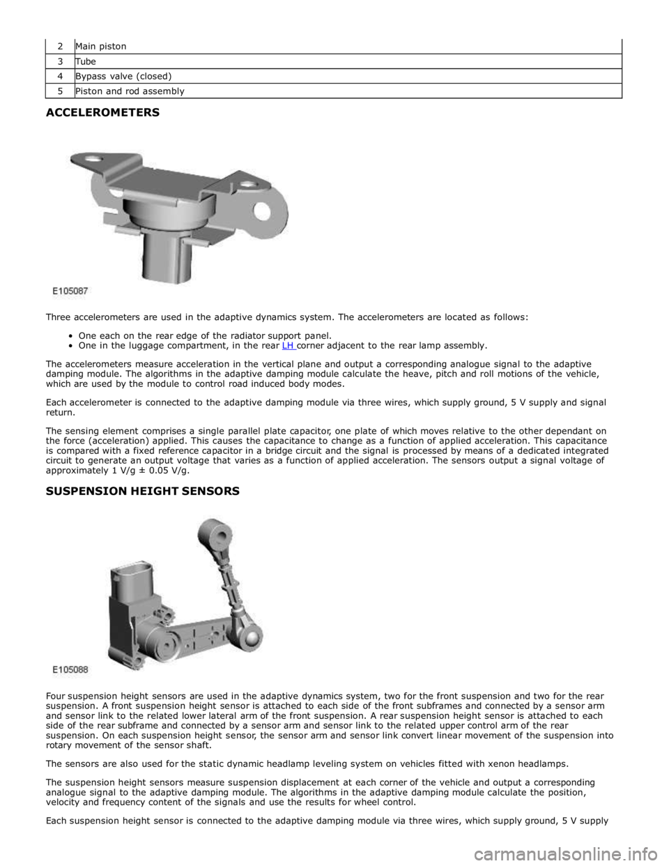
Three accelerometers are used in the adaptive dynamics system. The accelerometers are located as follows:
One each on the rear edge of the radiator support panel.
One in the luggage compartment, in the rear LH corner adjacent to the rear lamp assembly.
The accelerometers measure acceleration in the vertical plane and output a corresponding analogue signal to the adaptive
damping module. The algorithms in the adaptive damping module calculate the heave, pitch and roll motions of the vehicle,
which are used by the module to control road induced body modes.
Each accelerometer is connected to the adaptive damping module via three wires, which supply ground, 5 V supply and signal
return.
The sensing element comprises a single parallel plate capacitor, one plate of which moves relative to the other dependant on
the force (acceleration) applied. This causes the capacitance to change as a function of applied acceleration. This capacitance
is compared with a fixed reference capacitor in a bridge circuit and the signal is processed by means of a dedicated integrated
circuit to generate an output voltage that varies as a function of applied acceleration. The sensors output a signal voltage of
approximately 1 V/g ± 0.05 V/g.
SUSPENSION HEIGHT SENSORS
Four suspension height sensors are used in the adaptive dynamics system, two for the front suspension and two for the rear
suspension. A front suspension height sensor is attached to each side of the front subframes and connected by a sensor arm
and sensor link to the related lower lateral arm of the front suspension. A rear suspension height sensor is attached to each
side of the rear subframe and connected by a sensor arm and sensor link to the related upper control arm of the rear
suspension. On each suspension height sensor, the sensor arm and sensor link convert linear movement of the suspension into
rotary movement of the sensor shaft.
The sensors are also used for the static dynamic headlamp leveling system on vehicles fitted with xenon headlamps.
The suspension height sensors measure suspension displacement at each corner of the vehicle and output a corresponding
analogue signal to the adaptive damping module. The algorithms in the adaptive damping module calculate the position,
velocity and frequency content of the signals and use the results for wheel control.
Each suspension height sensor is connected to the adaptive damping module via three wires, which supply ground, 5 V supply
Page 495 of 3039
Published: 11-May-2011
Ride and Handling Optimization - Ride and Handling Optimization - System
Operation and Component Description
Description and Operation
JAGUARDRIVE CONTROL OPERATION
Engine Management System System Operation
The Engine Management System (EMS) varies the accelerator pedal maps to change the amount of torque per percentage of
pedal travel. The EMS can also change the accelerator pedal response to control the allowed torque change relative to the
speed of pedal travel.
Each driving mode uses a combination of operating parameters for each sub-system. Changing between driving modes initiates
a different set of operating characteristics, which will be noticeable to the driver. The driver will notice differences in engine
response when, for example, the accelerator pedal is held in a constant position and the driving mode is changed from Winter
to Dynamic, the driver will notice the torque and engine speed increase. Similarly, if the mode is changed from Normal or
Dynamic to Winter the driver will notice a reduction in torque and engine speed.
NOTE: The change in torque and engine speed can take approximately 30 seconds and care must be taken not to confuse
the JaguarDrive Control system operation with an EMS fault.
Transmission Control
The TCM (transmission control module) changes the shift maps for the JaguarDrive Control mode selected. This changes the
shift points providing early or late upshifts and downshifts. For example, on slippery surfaces in Winter mode the transmission
will select 2nd gear for starting from a standstill on a flat surface to minimize wheel slip.
Anti-lock Braking System Control
The ABS (anti-lock brake system) module controls several vehicle functions and adjusts the operating parameters of these
functions to optimize the selected JaguarDrive Control mode. Traction control uses different slip/acceleration thresholds to
improve traction and vehicle composure. For example, the system sensitivity is increased on slippery surfaces to reduce wheel
spin.
If TracDSC is selected or DSC is switched off, then subsequently the JaguarDrive Control mode is changed, DSC is automatically
switched back on (or to TracDSC for Dynamic mode).
The stability control uses different threshold values for the selected mode, reducing the requirement for the driver to change
the DSC system mode for optimum performance in various driving scenarios.
Incorrect Mode Usage
Selection of an inappropriate mode is discouraged in the following ways:
The active mode icon is continually displayed in the instrument cluster message center
In any special mode, when the ignition has been in the off position continuously for more than 6 hours, the JaguarDrive
Control system defaults to the special modes off (DSC on).
Selection of an inappropriate mode for the conditions will not endanger the driver or immediately cause damage to the vehicle.
Continued use of an inappropriate mode may reduce the life of some components. The driver may notice a different vehicle
response, with the engine and transmission responses being different than in the special modes off.
Driver Information
The instrument cluster contains a message center, which displays vehicle information to the driver. The message center
contains the JaguarDrive Control mode icons, which display the currently selected mode. If no symbol is displayed, no special
mode is selected and the system is in special modes off.
Any required changes to the subsystems are also passed to the driver in the form of warning illumination in the instrument
cluster or appropriate messages in the message center, DSC off for example.
In Dynamic mode when the transmission is in manual mode, the gear information is displayed in amber when the appropriate
engine speed is reached for optimum sporty change point.
DIAGNOSTICS
JaguarDrive Control relies on the correct functionality of the sub-systems. If one of the sub-systems develops a fault, the
JaguarDrive Control system will not function, even though the fault is not in the JaguarDrive Control system.
The JaguarDrive Selector module and rotary control should only be investigated if there are no apparent faults in any of the
sub-systems. If a fault in a sub-system is subsequently corrected, the JaguarDrive Control system will function normally after
an ignition on and off cycle.
Page 610 of 3039
BRAKE CALIPERS System Operation
When hydraulic pressure is supplied to the caliper, the pistons extend to force the inner pad against the brake disc. The caliper
reacts and slides along two guide pins to bring the outer pad into contact with the brake disc.
BRAKE PAD WEAR SENSORS
When a brake pad incorporating a brake pad wear sensor is approximately 75% worn, the sensor wire within the pad material
is worn through and the brake pad wear sensor goes open circuit. When the instrument cluster detects the open circuit, it
illuminates the amber LED (light emitting diode) in the brake warning indicator, displays an appropriate warning in the
message center and sounds a warning chime.
Refer to: Instrument Cluster (413-01 Instrument Cluster, Description and Operation).
NOTE: A new pad wear sensor lead must be fitted whenever the brake pads are changed, irrespective of the brake pad
warning sensor being triggered.
BRAKE CALIPERS Component Description
Each caliper is mounted within a fixed carrier that is secured to the front wheel knuckle with two bolts. The inboard brake pad
of the LH (left-hand) brake incorporates a wear sensor.
Each outboard brake pad is installed with a pressed steel anti-rattle spring. On SC (supercharger) vehicles, a badge with the
'R' symbol is formed on the anti-rattle spring.
BRAKE PAD WEAR SENSORS
The brake pad wear sensor is wired in series with a wear sensor on the RH (right-hand) rear brake and the instrument cluster.
If the thickness of one of the brake pads connected to a wear sensor decreases to a predetermined limit, the instrument
cluster illuminates the brake warning indicator.
Page 632 of 3039
BRAKE CALIPERS System Operation
When hydraulic pressure is supplied to the caliper, the pistons extend to force the inner pad against the brake disc. The caliper
reacts and slides along two guide pins to bring the outer pad into contact with the brake disc.
BRAKE PAD WEAR SENSORS
When a brake pad incorporating a brake pad wear sensor is approximately 75% worn, the sensor wire within the pad material
is worn through and the brake pad wear sensor goes open circuit. When the instrument cluster detects the open circuit, it
illuminates the amber LED (light emitting diode) in the brake warning indicator, displays an appropriate warning in the
message center and sounds a warning chime.
Refer to: Instrument Cluster (413-01 Instrument Cluster, Description and Operation).
NOTE: A new pad wear sensor lead must be fitted whenever the brake pads are changed, irrespective of the brake pad
warning sensor being triggered.
BRAKE CALIPERS Component Description
Each caliper is mounted within a fixed carrier that is secured to the rear wheel knuckle with two bolts. Each outboard brake pad
is installed with a wire anti-rattle spring.
The brake calipers on SC (supercharger) vehicles are painted and also include a logo badge, secured with two screws, which
must be removed in order to change the brake pads.
The inboard brake pad of the RH (right-hand) brake incorporates a wear sensor.
BRAKE PAD WEAR SENSORS
The brake pad wear sensor is wired in series with a wear sensor on the LH (left-hand) front brake and the instrument cluster. If
the thickness of one of the brake pads connected to a wear sensor decreases to a predetermined limit, the instrument cluster
illuminates the brake warning indicator.
Page 648 of 3039
7 Instrument cluster 8 Parking brake switch 9 Parking brake actuator
Static Apply System Operation
The EPB module receives a vehicle speed signal from the ABS (anti-lock brake system) module on the high speed CAN bus. If the parking brake switch is pulled to the 'Apply' position and vehicle speed is less than 2 mph (3 km/h), the EPB module will
instigate its 'Static Apply' mode and drive the actuator to apply full parking brake force to the rear wheels.
The EPB module monitors the current drawn by the actuator and compares this to information held within its configuration
software to determine when full braking force has been applied.
Dynamic Apply
There are two 'Dynamic Apply' modes; low speed dynamic and high speed dynamic. The low speed dynamic mode operates at
speeds between 2 mph (3 km/h) and 20 mph (32 km/h). The high speed dynamic mode operates at speeds above 20 mph (32
km/h).
If the parking brake switch is pulled up to the 'Apply' position and vehicle speed is within the low speed dynamic range, the
EPB module drives the actuator to apply full parking brake force to the rear wheels.
If the parking brake switch is pulled up to the 'Apply' position and vehicle speed is within the high speed dynamic range, the
EPB module will apply braking force to the rear wheels at a slower rate until full braking load is reached or the switch is
released. The rate with which braking force is applied is controlled by the EPB module, which monitors both current drawn by
the actuator and positional information from the actuator hall sensor and compares this to information held within its
configuration software.
Drive Away Release
The EPB module will initiate its 'Drive Away Release' function and automatically release the parking brake if the following
conditions are detected:
The engine is running.
Drive , or reverse is selected.
Positive throttle movement is detected.
The EPB module receives messages of gear selector position and throttle angle over the high speed CAN bus from the TCM (transmission control module) and the ECM (engine control module) respectively.
Release from Park
The EPB module will initiate its 'Release from Park' function and automatically release the parking brake if the gear selector is
moved from Park to any position except Neutral.
Repairs
Before carrying out any work on the parking brake system, the Jaguar approved diagnostic system must be connected and the
'parking brake unjam' routine run. The routine can be found in the 'Vehicle Configuration' area, under the 'Set-up and
Configuration' menu. After any work has been carried out on the parking brake, the system will require resetting.
CAUTION: Do not use the 'Emergency Release' tool to allow work to be carried out on the parking brake. Work can only be
carried out on the parking brake system after the 'parking brake unjam' routine has been run.
Resetting
If the electrical supply is disconnected from the EPB module, the actuator will loose its position memory. On battery
re-connection and ignition on, 'APPLY FOOT AND PARK BRAKE' will be displayed in the instrument cluster message center
indicating the parking brake requires resetting.
Refer to: Parking Brake (206-05, Diagnosis and Testing).
Operating Voltages
The EPB module will only operate the actuator if the power supply from the battery is between 9 V and 16 V. At any voltage
within this range, the actuator is able to fully tighten and release the brake cables. If the power supply falls outside of the
range, a fault code is stored in the EPB module and can be retrieved using the Jaguar approved diagnostic system.
Page 692 of 3039
Published: 11-May-2011
Anti-Lock Control - Stability Assist - Anti-Lock Control - Stability Assist - Overview
Description and Operation
Overview
The ABS (anti-lock brake system) and DSC (dynamic stability control) system features a Bosch modulator, which is an
integrated four-channel HCU (hydraulic control unit) and ABS module. The unit is located in the rear of the engine compartment on the passenger side, and is installed in the brake hydraulic circuit between the brake master cylinder and the four brake
calipers.
The ABS module is connected to the high speed CAN (controller area network) bus, and actively interacts with other vehicle system control modules and associated sensors to receive and transmit current vehicle operating information.
When required, the ABS module will actively intervene and operate the HCU during braking or vehicle maneuvers to correct the vehicle attitude, stability, traction or speed. During incidents of vehicle correction, the ABS module may also request the ECM (engine control module) to control engine power in order to further stabilize and correct the vehicle.
To provide full system functionality, the ABS and DSC system comprise the following components: DSC switch.
Four wheel speed sensors.
Steering angle sensor.
Yaw rate and lateral acceleration sensor.
Stoplamp switch.
Instrument cluster indicator lamps.
Integrated ABS module and HCU. Brake booster vacuum sensor (3.0L vehicles only).
Two variants of ABS module are available, Bosch ESP®8.1 and Bosch ESP®plus8.1. The Bosch ESP®plus8.1 system is fitted to vehicles with ACC (adaptive cruise control) and incorporates a new feature to Jaguar known as 'electronic brake prefill'.
Electronic brake prefill, senses any rapid throttle lift off, activating a small brake hydraulic pressure build-up of approximately 3
to 5 bar (43.5 to 72.5 lbf/in²) in anticipation of the brakes being applied. This application produces a quicker brake pedal
response and consequently slightly shorter stopping distances. When the ECM detects rapid throttle lift off it signals the ABS module which controls the HCU to apply a low brake pressure to assist in a quicker brake application.
NOTE: All vehicles with ACC are supported by the Bosch ESP®plus8.1 system.
The ABS provides the following brake functions that are designed to assist the vehicle or aid the driver: ABS. DSC, including Trac DSC.
CBC (corner brake control).
EBD (electronic brake force distribution).
ETC (electronic traction control).
EBA (emergency brake assist).
EDC (engine drag-torque control).
Understeer control.
Electronic brake prefill (vehicles with ACC only).
Brake vacuum assist (3.0L vehicles only).
All the brake functions listed are automatically active when the ignition is in power mode and the engine is running. The DSC
system can be selected to off using the DSC switch.
WARNING: Although the vehicle is fitted with DSC, it remains the drivers responsibility to drive safely according to the
prevailing conditions.