sensor JAGUAR XJ6 1994 2.G Electrical Diagnostic Manual
[x] Cancel search | Manufacturer: JAGUAR, Model Year: 1994, Model line: XJ6, Model: JAGUAR XJ6 1994 2.GPages: 327, PDF Size: 13.73 MB
Page 116 of 327
n E I ectr ica I
FAULT CODE 12
Low Battery Voltage
Normal Operation
The DM monitors voltage at pin 13 which should be equal to battery voltage. If a voltage lower than 9V is detected at pin 13 the MIL Lamp will illuminate and fault code 12 will be present.
Possible Causes
Drop in battery voltage to DM pin 13 caused by:
0 Open circuit to pin 13 from battery.
0 Short circuit to ground on battery feed circuit.
0 Safing sensor feed shorted to ground.
0 Safing sensor internal short to ground.
0 Faulty charging system draining battery voltage.
Fault Oiagnosis
1. Battery voltage test
Disarm the SRS system.
8 Disconnect the DM.
8 Switch on the ignition.
Measure the voltage between DM connector pin 13 (+ve) and pin 3(-ve).
If battery voltage is present at pin 13, renew the DM.
8 Arm and verify the SRS system.
8 If battery voltage is not present, go to step 2.
2.
Fusecheck
8 Check fuse 17 in the RH fuse-box.
If the fuse has blown, check for short circuit to ground between fuse and pin 13 DM connector.
8 Renew the fuse, go to step 3.
8 If the fuse has not blown, check for open circuit between battery positive terminal and pin 13 DM connector.
3. Short circuit check
* Switch off the ignition.
8 Connect the DM.
8 Has the fuse blown 1
Yes -
= Short circuit to ground from pin 15 DM (R/ W) to pin 3 safing sensor, or from pin 23 DM (Y / P) to pin 6 safing sensor.
8 Intermittent short circuit to ground; check wire (R / W) from pin 15 DM to pin 3 safing sensor, and, wire (Y/ P) from
NO -
pin 23 DM to pin 6 safing sensor.
4. On completion
8 Renew the fuse as necessary.
8 Arm and verify the SRS system.
Issue 1 August 1994 15.1 - 10 X300 EDM
Page 117 of 327
Electricalschematic - Fault Code 12
0
a
e
+12v
1 p=-+-
rn 4 rn
-
P15 !J23 P16
P12
P13
PO3 I
10
1. Instrument Panel Fuse 6. Passenger-side Air Bag 2. Engine Compartment Fuse 7. RH Impact Sensor 3. Safing Sensor 8. LH Impact Sensor
4. Cable Reel Cassettes 9. Air Bag MIL Lamp
5. Driver-side Air Bag 10. Diagnostic Module
Fig. 1
J86-1665
X300 EDM 15.1 - 11 Issue 1 August 1994
Page 118 of 327
rl Electrical
FAULTCODE 13
Air Bag Shorted to Ground
Normal Operation
The DM monitors voltage level at pins 11 and 12 which varies in accordance with charging voltage. If voltage measured
at these two pins falls below 2V the MIL Lamp will illuminate and fault code 13 will be present, indicating a possible
short to ground.
During the presence of fault code 13 the DM internal thermal fuse will blow, disabling the air bag deployment circuit.
If voltage to pins 11 and 12 is restored after the fuse has blown, fault code 51, open internal fuse,
will also be present.
Fault code 13 will be present only as long as the short to ground remains.
Possible Causes
Short to ground in any of the following circuits:
0 Air bag supply wiring.
0 Air bag internal.
0 Cable reel cassette internal.
0 Safing sensor supply wiring.
0 Safing sensor internal.
Fault Diagnosis
1. Air bag(s) -short circuit
. Disarm the SRS system.
. Disconnect both air bag modules multi-plug connector.
. Switch ignition ON.
. Is fault code 13 still present ?
Yes - Proceed to step 2.
No - Proceed to step 3.
2. Cable reel cassette
-short circuit
Examine wiring and connector where cable reel cassette mates to the main harness, below the steering column.
If a fault cannot be located, disconnect cable reel cassette from main harness.
. Connect air bag simulator to the main vehicle harness in place of the cable reel cassettes.
. Measure resistance between pin 11 DM and pin 3 (ground).
. Is pin 11 short circuit to ground ?
No - Proceed to fault code 51.
Yes
- Examine wiring and connections between DM, both air bags and safing sensor. Rectify faults as necessary.
If a fault is located, rectify and proceed to step 3.
3. Air bag modules
-check
. Ensure shorting bar is correctly installed to passenger-side air bag connector.
. Measure resistance between connector terminals and module casing.
If resistance value shows a short to ground, renew the module.
. If resistance shows open circuit, repeat test for driver-side module, renew as necessary.
Proceed to fault code 51 on successful diagnosis.
Issue 1 August 1994 15.1 - 12 X300 EDM
Page 119 of 327
E I ect r ical n
-
Electrical schematic - Fault Code 13
0
0
0
+12v
+12v
I_i
I 10
4
1. Instrument Panel Fuse 6. Passenger-side Air Bag
2. Engine Compartment Fuse 7. RH Impact Sensor
3. Safing Sensor 8. LH Impact Sensor
4. Cable Reel Cassettes 9. Air Bag MIL Lamp 5. Driver-side Air Bag 10. Diagnostic Module
Fig. 1
586-1668
X300 EDM 15.1 - 13 Issue 1 August 1994
Page 120 of 327
Electrical I3
FAULTCODE 14
Front Impact Sensor Circuit Shorted to Ground
Normal Operation
The DM monitors voltage level at pins 2 and 6. If this voltage falls to 5 volts, or less, the MIL Lamp will illuminate and
fault code 14 will be present, indicating a short circuit to ground on either of the two front impact sensorcircuits. During
the presence of fault code 14 the DM internal thermal fuse will blow, disabling the air bag deployment circuit. If voltage
to pins
2 and 6 is restored after the fuse has blown,fault code 51, open internal fuse will be present. Fault code 14 will
be present only as long as the short to ground remains.
Possible Causes
Short to ground in any of the following circuits:
0 Front impact sensor wiring.
0 Disconnection, or poor connection of harness.
0 Front impact sensors internal ground.
Fault Diagnosis
1. Sub-circuit identification
. Disarm SRS system.
. Remove plastic locking wedge from the grey DM connector.
. Measure resistance between connector pin 3 and all of the following pins; 2,6, 17 and 18.
9 Does any resistance reading indicate short circuit ?
Yes - Renew faulty sensor.
No - Examine sensor wiring harness, locate and rectify faults as necessary.
Proceed to fault code 51 on successful diagnosis.
rm
0
0
0
0
X300 EDM Issue 1 August 1994 15.1 - 14
Page 121 of 327
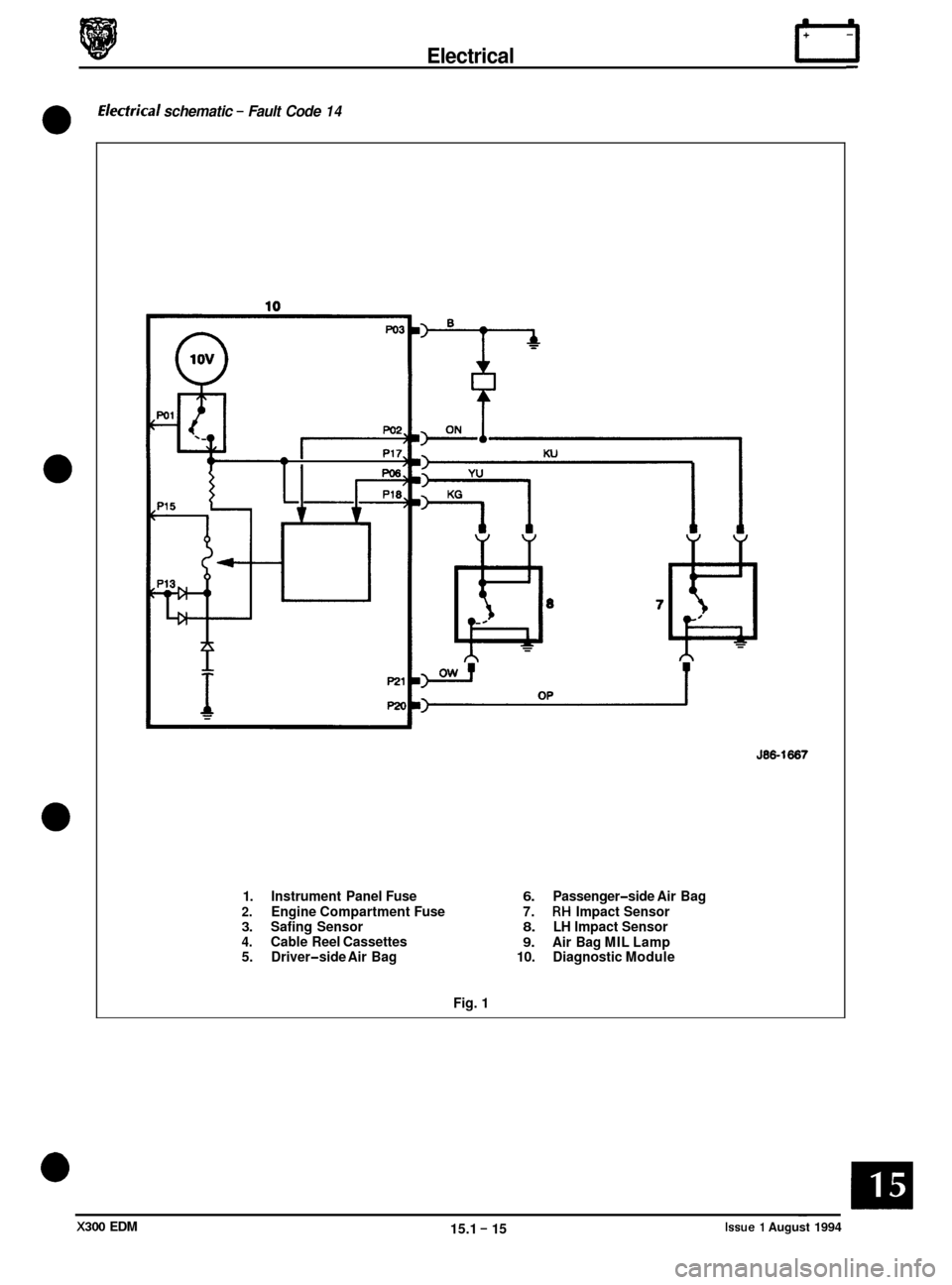
Electrical rl
Electrkal schematic - Fault Code 14
0
0
0
0
J86-1667
1. Instrument Panel Fuse 6. Passenger-side Air Bag
2. Engine Compartment Fuse 7. RH Impact Sensor 3. Safing Sensor 8. LH Impact Sensor 4. Cable Reel Cassettes 9. Air Bag MIL Lamp
5. Driver-side Air Bag 10. Diagnostic Module
Fig. 1
X300 EDM 15.1 - 15 ~~ Issue 1 August 1994
Page 122 of 327
FAULTCODE 21
Safing impact Sensor Incorrectly Mounted to Vehicle
Normal Operation
The DM monitors the resistance value between pins 16 and 3. If a resistance value of greater than 2.051 is detected the
MIL Lamp will illuminate and fault code 21 will be present, indicating incorrect mounting of the safing impact sensor.
Secure connections to ground at both the sensor case and the vehicle are necessary to avoid this fault.
Possible Causes
0 Poor or dirty connection between safing sensor case and vehicle ground.
0 Poor or dirty termination at safing sensor internal ground.
0 Open circuit on wiring between DM pin 16 and safing sensor ground terminal.
Fault Diagnosis
1. Resistance - check
Disarm SRS system.
Disconnect battery ground lead.
Measure resistance between pin 3 (ground) and pin 16 (ground - safing sensor).
Is resistance value greater than 251 ?
No - Proceed to step 2
Yes
- Renew DM
2. Sensor ground
-check
Disconnect safing sensor from harness.
Measure resistance between sensor pin 5 and sensor mounting (chassis ground).
Is resistance value greater than 251 ?
Yes - Proceed to step 3
No - Examine wiring between internal sensor ground and harness connection 10. Rectify faults as necessary.
3. Sensor mounting -check
Remove safing sensor from mounting.
* Clean all mounting surfaces thoroughly and refit sensor.
Re-test resistance between harness connection 10 and sensor internal ground.
* Is resistance value greater than 251 ?
Yes - Renew sensor
No - Refit sensor and connect harness and battery ground lead.
4. On completion
Arm and verify the SRS system.
0
0
0
Issue 1 August 1994 15.1 - 16 X300 EDM
Page 123 of 327
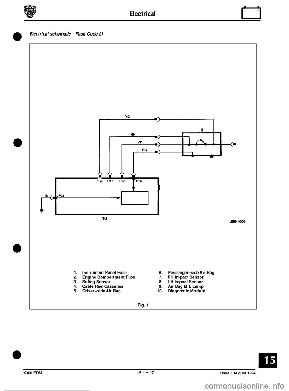
E I ect r ica I rl
Electrkal schematic - Fault Code 2 1
0
0
0
0
2 P15 P23 PI 6
i I
10
1. Instrument Panel Fuse 6. Passenger-side Air Bag 2. Engine Compartment Fuse 7. RH Impact Sensor
3. Safing Sensor 8. LH Impact Sensor 4. Cable Reel Cassettes 9. Air Bag MIL Lamp
5. Driver-side Air Bag 10. Diagnostic Module
Fig. 1
J86-1668
X300 EDM 15.1 - 17 Issue 1 August 1994
Page 124 of 327
rl E I ect r ica I
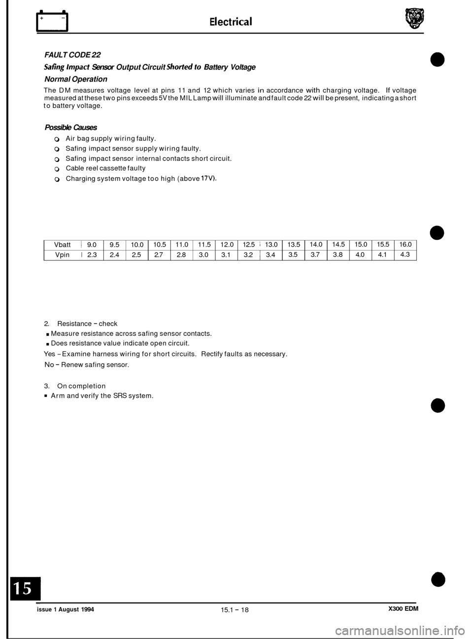
Vbatt 1 9.0 9.5
10.0 10.5
11.0 11.5 12.0 12.5 ~ 13.0
13.5
Vpin
I 2.3 2.4 2.5 2.7 2.8 3.0 3.1
3.2 1 3.4 3.5
FAULT CODE 22
Safing Impact Sensor
Output Circuit Shorted to Battery Voltage
Normal Operation
The DM measures voltage level at pins 11 and 12 which varies in accordance with charging voltage. If voltage
measured at these two pins exceeds
5V the MIL Lamp will illuminate and fault code 22 will be present, indicating a short
to battery voltage.
14.0 14.5 15.0 15.5 16.0
3.7 3.8 4.0
4.1 4.3
Possible Causes
0 Air bag supply
wiring faulty.
0 Safing impact sensor supply wiring faulty.
0 Safing impact sensor internal contacts short circuit.
0 Cable reel cassette faulty
0 Charging system voltage too high (above 17V).
2. Resistance - check
. Measure resistance across safing sensor contacts.
. Does resistance value indicate open circuit.
Yes
-Examine harness wiring for short circuits. Rectify faults as necessary.
No - Renew safing sensor.
3. On completion
Arm and verify the SRS system.
0
0
0
0 ~
issue 1 August 1994 15.1 - 18 X300 EDM
Page 125 of 327
Electrical IT
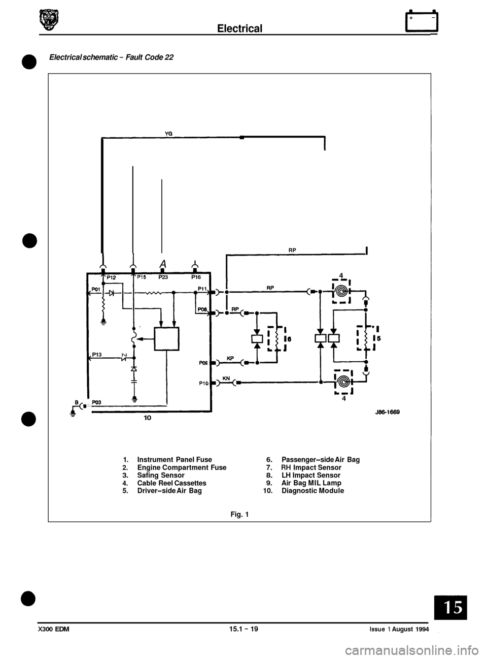
Electrical schematic - Fault Code 22
0
0
0
PO'
A A . P15 P23 P16
c-
PO9
PI E
P13 N
PO3 I
10
RP I
4
'I
15
1
4
J86-1669
1. Instrument Panel Fuse 6. Passenger-side Air Bag
2. Engine Compartment Fuse 7. RH Impact Sensor 3. Safing Sensor 8. LH Impact Sensor
4. Cable Reel Cassettes 9. Air Bag MIL Lamp
5. Driver-side Air Bag 10. Diagnostic Module
Fig. 1
X300 EDM 15.1 - 19 Issue 1 August 1994