sensor JAGUAR XJ6 1994 2.G Electrical Diagnostic Manual
[x] Cancel search | Manufacturer: JAGUAR, Model Year: 1994, Model line: XJ6, Model: JAGUAR XJ6 1994 2.GPages: 327, PDF Size: 13.73 MB
Page 126 of 327
Electrical rl
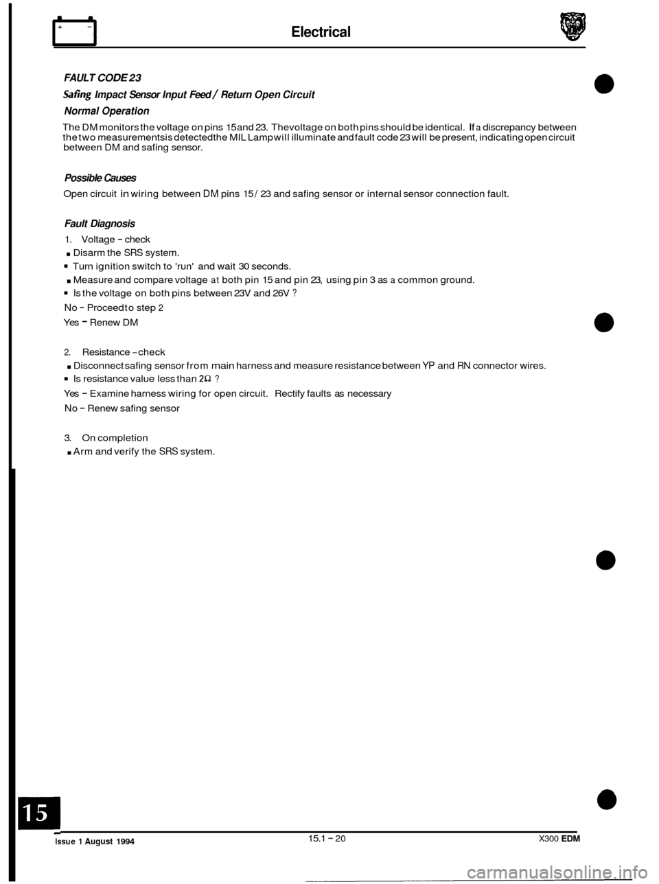
FAULT CODE 23
Safing Impact Sensor Input Feed / Return Open Circuit
Normal Operation
The DM monitors the voltage on pins 15 and 23. Thevoltage on both pins should be identical. If a discrepancy between
the two measurements is detected the MIL Lamp will illuminate and fault code 23 will be present, indicating open circuit
between DM and safing sensor.
Possible Causes
Open circuit in wiring between DM pins 15 / 23 and safing sensor or internal sensor connection fault.
Fault Diagnosis
1. Voltage - check
. Disarm the SRS system.
. Measure and compare voltage at both pin 15 and pin 23, using pin 3 as a common ground.
No - Proceed to step 2
Yes - Renew DM
Turn
ignition switch to 'run' and wait 30 seconds.
Is the voltage on both pins between 23V and 26V ?
2. Resistance -check
. Disconnect safing sensor from main harness and measure resistance between YP and RN connector wires.
Is resistance value less than 2S2 ?
Yes - Examine harness wiring for open circuit. Rectify faults as necessary
No - Renew safing sensor
3. On completion
. Arm and verify the SRS system.
15.1
- 20 X300 EDM Issue 1 August 1994
0
0
0
0
Page 127 of 327
Electrical rl
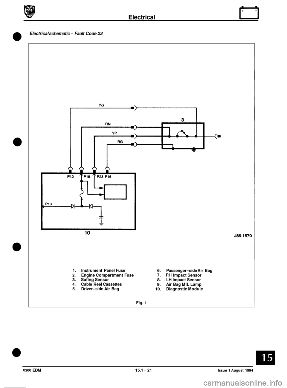
Electrical schematic - Fault Code 23
0
0
0
-I
YG
f
P13
10
1. Instrument Panel Fuse
J86-1670
6. Passenger-side Air Bag 2. Engine Compartment Fuse 7. RH Impact Sensor 3. Safing Sensor 8. LH Impact Sensor 4. Cable Reel Cassettes 9. Air Bag MIL Lamp 5. Driver-side Air Bag 10. Diagnostic Module
Fig.
1
X300 EDM 15.1 - 21 Issue 1 August 1994
Page 128 of 327
Electrical
0
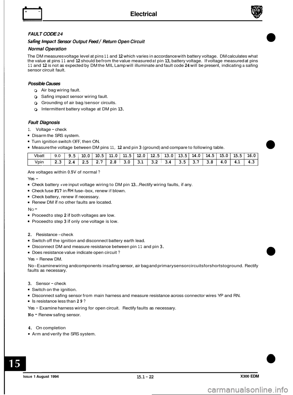
FAULT CODE 24
Safing Impact Sensor Output Feed / Return Open Circuit
Normal Operation
The DM measures voltage level at pins 11 and 12 which varies in accordance with battery voltage. DM calculates what
the value at pins 11 and 12 should be from the value measured at pin 13, battery voltage. If voltage measured at pins 11 and 12 is not as expected by DM the MIL Lamp will illuminate and fault code 24 will be present, indicating a safing
sensor circuit fault.
Vbatt
9.0 9.5 1 10.0 10.5
11.0 i 11.5 12.0 12.5 I 13.0 13.5 14.0
14.5 15.0
15.5
Vpin 2.3 2.4 ~ 2.5
2.7
2.8 ~ 3.0
3.1 3.2 1 3.4 3.5 3.7 3.8 4.0
4.1
Possible Causes
0 Air bag wiring fault.
0 Safing impact sensor wiring fault.
0 Grounding of air bag /sensor circuits.
0 Intermittent battery voltage at DM pin 13.
16.0 4.3
Fault Diagnosis
1. Voltage - check
8 Disarm the SRS system.
8 Turn ignition switch OFF, then ON.
8 Measure the voltage between DM pins 11, 12 and pin 3 (ground) and compare to following table.
Are voltages within
0.5V of normal ?
Yes -
8 Check battery +ve input voltage wiring to DM pin 13.. Rectify wiring faults, if any.
8 Check fuse F17 in RH fuse-box, renew if blown.
8 Check battery, renew if necessary.
8 Renew DM if no other faults are located.
8 Proceed to step 2 if both voltages are low.
8 Proceed to step 3 if only one voltage is low.
N
O -
2. Resistance -check
8 Switch off the ignition
and disconnect battery earth lead.
8 Disconnect DM and measure resistance between pin 11 and pin 3.
8 Does resistance value indicate open circuit ?
Yes - Renew DM.
No
-Examine wiring andcomponents insafing sensor, air bag and primarysensorcircuitsforshortstoground. Rectify
faults as necessary.
3. Sensor - check
8 Switch on the ignition.
8 Disconnect safing sensor from main harness and measure resistance across connector wires YP and RN.
8 Is resistance less than 29 ?
Yes - Examine harness wiring for open circuit. Rectify faults as necessary.
No - Renew safing sensor.
4. On completion
8 Arm and verify the SRS system.
X300 EDM Issue 1 August 1994 15.1 - 22
Page 129 of 327
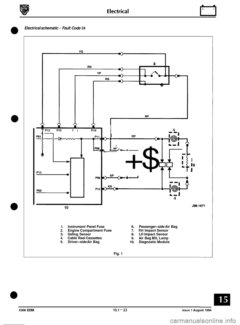
Electrical schematic - Fault Code 24
0
P12 P15 f
1
'I' I P16
--n
P13
w3
PO8
P10
10
I A 7 I - -m I RP
I'i _-
I>.---
+$ I L t
I
I5
I
L-J 4
J86-1671
1. Instrument Panel Fuse 6. Passenger-side Air Bag 2. Engine Compartment Fuse 7. RH Impact Sensor 3. Safing Sensor 8. LH Impact Sensor 4. Cable Reel Cassettes 9. Air Bag MIL Lamp 5. Driver-side Air Bag 10. Diagnostic Module
Fig.
1
X300 EDM 15.1 - 23 Issue 1 August 1994
Page 131 of 327
Electrical rl
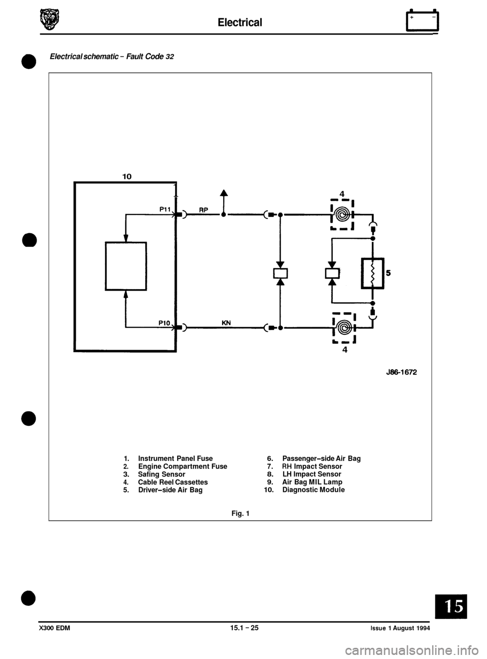
Electrical schematic - Fault Code 32
0
10
1 4
U 4
J86-1672
1. Instrument Panel Fuse 6. Passenger-side Air Bag 2. Engine Compartment Fuse 7. RH Impact Sensor
3. Safing Sensor 8. LH Impact Sensor
4. Cable Reel Cassettes 9. Air Bag MIL Lamp
5. Driver
-side Air Bag 10. Diagnostic Module
Fig. 1
X300 EDM 15.1 - 25 Issue 1 August 1994
Page 133 of 327
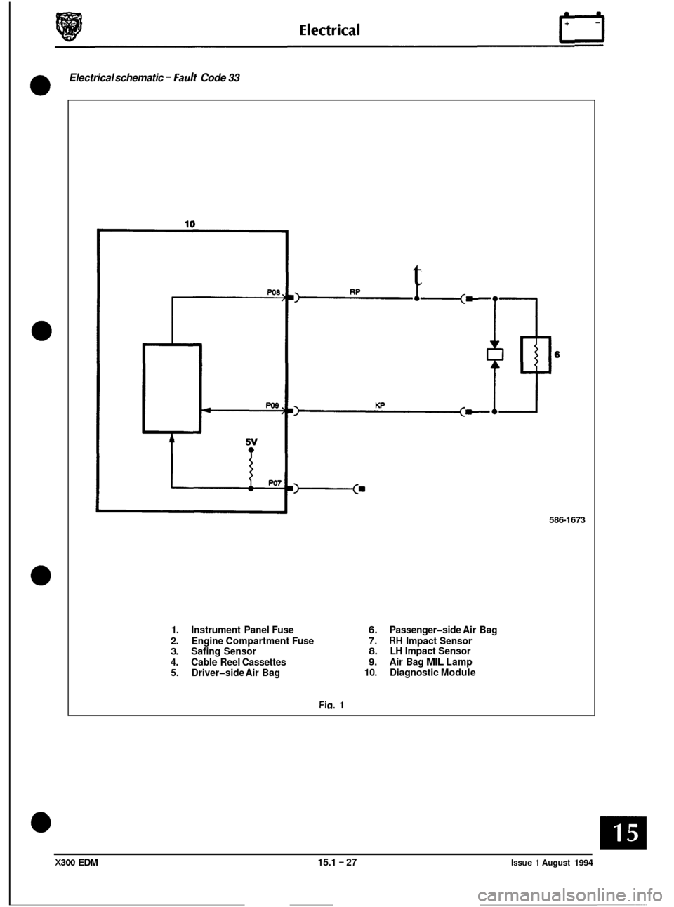
Electrical schematic - Fault Code 33
0
0
0
0
c
5v ?
t
-=
586-1673
1. Instrument Panel Fuse 6. Passenger-side Air Bag
2. Engine Compartment Fuse 7.
RH Impact Sensor 3. Safing Sensor 8. LH Impact Sensor
4. Cable Reel Cassettes 9. Air Bag MIL Lamp
5. Driver
-side Air Bag 10.
Diagnostic Module
Fia. 1
X300 EDM 15.1 - 27 Issue 1 August 1994
Page 135 of 327
Electrical
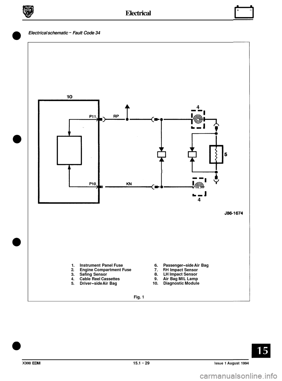
Electrical schematic - Fault Code 34
0
0
0
10
i A
P10,
A 4
I
(c KN I I L-J
4
J86-1674
1. Instrument Panel Fuse 6. Passenger-side Air Bag
2. Engine Compartment Fuse
7. RH Impact Sensor 3. Safing Sensor 8. LH Impact Sensor
4. Cable Reel Cassettes 9.
Air Bag MIL Lamp 5. Driver-side Air Bag 10. Diagnostic Module
Fig.
1
X300 EDM 15.1 - 29 Issue 1 August 1994
Page 137 of 327
Electrical n
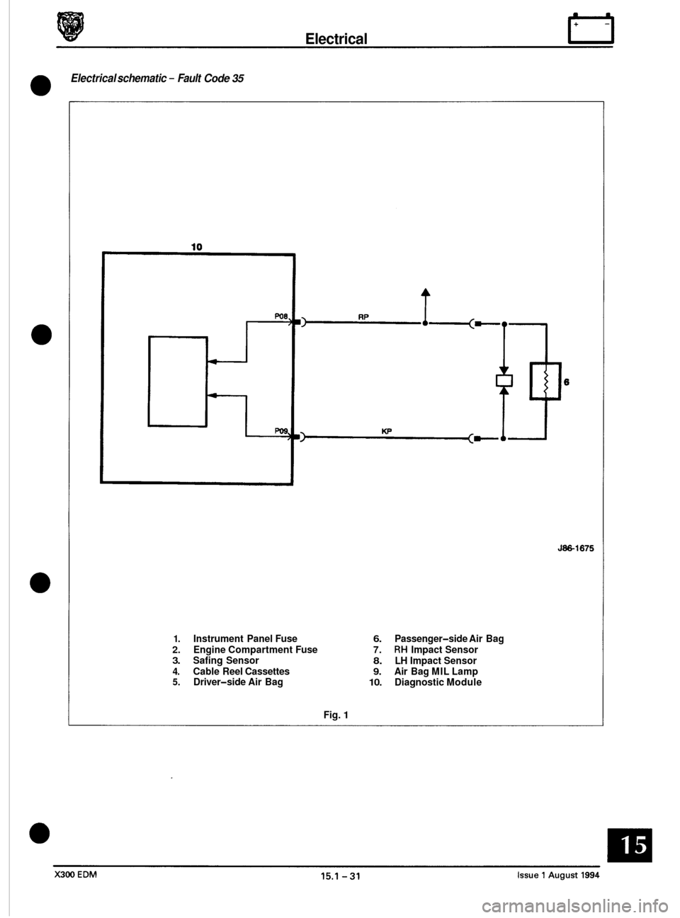
Electrical schematic - Fault Code 35
0
J86-1675
1. Instrument Panel Fuse 6. Passenger-side Air Bag
2. Engine Compartment Fuse 7. RH Impact Sensor 3. Safing Sensor 8. LH Impact Sensor 4. Cable Reel Cassettes 9. Air Bag MIL Lamp 5. Driver-side Air Bag 10. Diagnostic Module
Fig.
1
Page 138 of 327
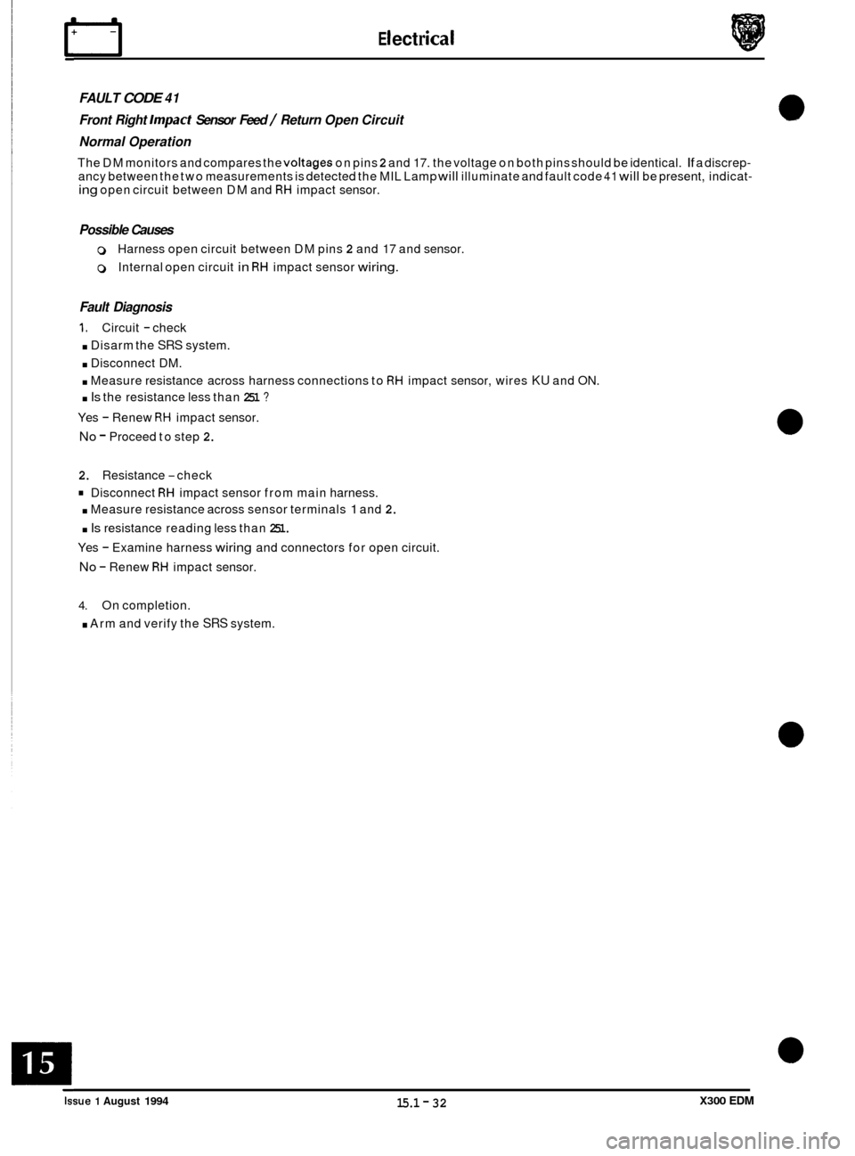
rl E I ect r ica I
FAULT CODE 41
Front Right Impact Sensor Feed / Return Open Circuit
Normal Operation
The DM monitors and compares the voltages on pins 2 and 17. the voltage on both pins should be identical. If a discrep- ancy between the two measurements is detected the MIL Lamp will illuminate and fault code 41 will be present, indicat- ing open circuit between DM and RH impact sensor.
Possible Causes
0 Harness open circuit between DM pins 2 and 17 and sensor.
0 Internal open circuit in RH impact sensor wiring.
Fault Diagnosis
1. Circuit - check
. Disarm the SRS system.
. Disconnect DM.
. Measure resistance across harness connections to RH impact sensor, wires KU and ON.
. Is the resistance less than 251 ?
Yes - Renew RH impact sensor.
No - Proceed to step 2.
2.
Resistance -check
Disconnect RH impact sensor from main harness.
. Measure resistance across sensor terminals 1 and 2.
. Is resistance reading less than 251.
Yes - Examine harness wiring and connectors for open circuit.
No - Renew RH impact sensor.
4. On completion.
. Arm and verify the SRS system.
e
0
0
X300 EDM 15.1 - 32 Issue 1 August 1994
Page 139 of 327
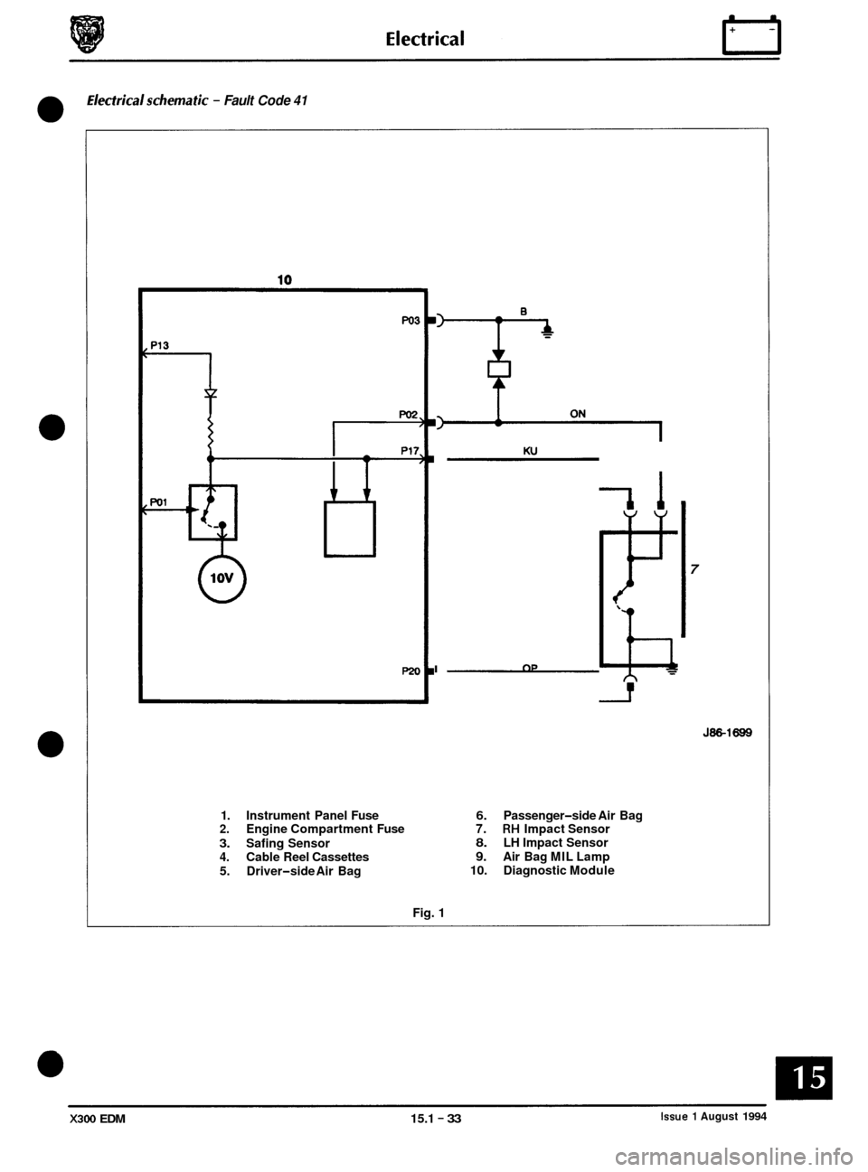
Electricalschematic - Fault Code 41
0
0
0
0
Ku
I OP ~
7
J86-1699
1.
Instrument Panel Fuse 6. Passenger-side Air Bag 2. Engine Compartment Fuse 7. RH Impact Sensor
3. Safing Sensor 8. LH Impact Sensor
4. Cable Reel Cassettes 9. Air Bag MIL Lamp
5. Driver
-side Air Bag 10. Diagnostic
Module
Fig. 1
Issue 1 August 1994 X300 EDM 15.1 - 33