engine JAGUAR XJ6 1994 2.G Workshop Manual
[x] Cancel search | Manufacturer: JAGUAR, Model Year: 1994, Model line: XJ6, Model: JAGUAR XJ6 1994 2.GPages: 521, PDF Size: 17.35 MB
Page 333 of 521
Climate Control Systems
14.13 SYSTEM CHECKING WITH MANIFOLD GAUGE Sm
14.13.1 Evacuating the Manifold Gauge Set
Attach the centre (service) hose to a vacuum pump and start the pump. Open fully both high anddow valves and allow
the vacuum to remove air and moisture from the manifold set for at least five minutes.
Turn the vacuum pump off and isolate it from the centre service hose but do not open the hose to atmosphere.
CAUTION: It is imperative that the vacuum pump is not subjected to a positive pressure of any degree. Therefore
the pump must be frtted with an isolation valve at the centre (service hose) connection and this valve
must be closed before the pump is switched off. This operation replaces the 'purge' procedure used on
previous systems. Observe the manufacturefs recommendation with regard to vacuum pump oil
changes.
14.13.2 Connecting the Manifold Gauge Set
CAUTION: Only use hoses with connectors which are dedicated to HFC 134A charge ports.
Attachment of the hose quick release connectors to the high and low side system ports is straightfotward, provided
that the high and low valves are closed and the system is NOT operational.
Assessment of system operating efficiency and fault classification may be achieved by using the facilities on your
Re- covery / Recharging / Recycling station, follow the manufacturers instructions implicitly and observe all safety con- siderations.
WARNING: UNDER NO CIRCUMSTANCES SHOULD THE CONNECTIONS BE MADE WITH THE SYSTEM IN
OPERATION OR THE VALVES OPEN. SHOULD THE VALVES BE OPEN AND A VACUUM PUMP OR
REFRIGERANT CONTAINER ATTACHED, AN EXPLOSION COULD OCCUR AS A RESULT OF HIGH
PRESSURE REFRIGERANT BEING FORCED BACK INTO THE VACUUM PUMP
OR CONTAINER.
14.13.3 Stabilizing the System
Accurate test gauge data will only be attained if the system temperatures and pressures are stabilized.
Ensure that equipment and hoses cannot come into contact with engine moving parts or sources of heat.
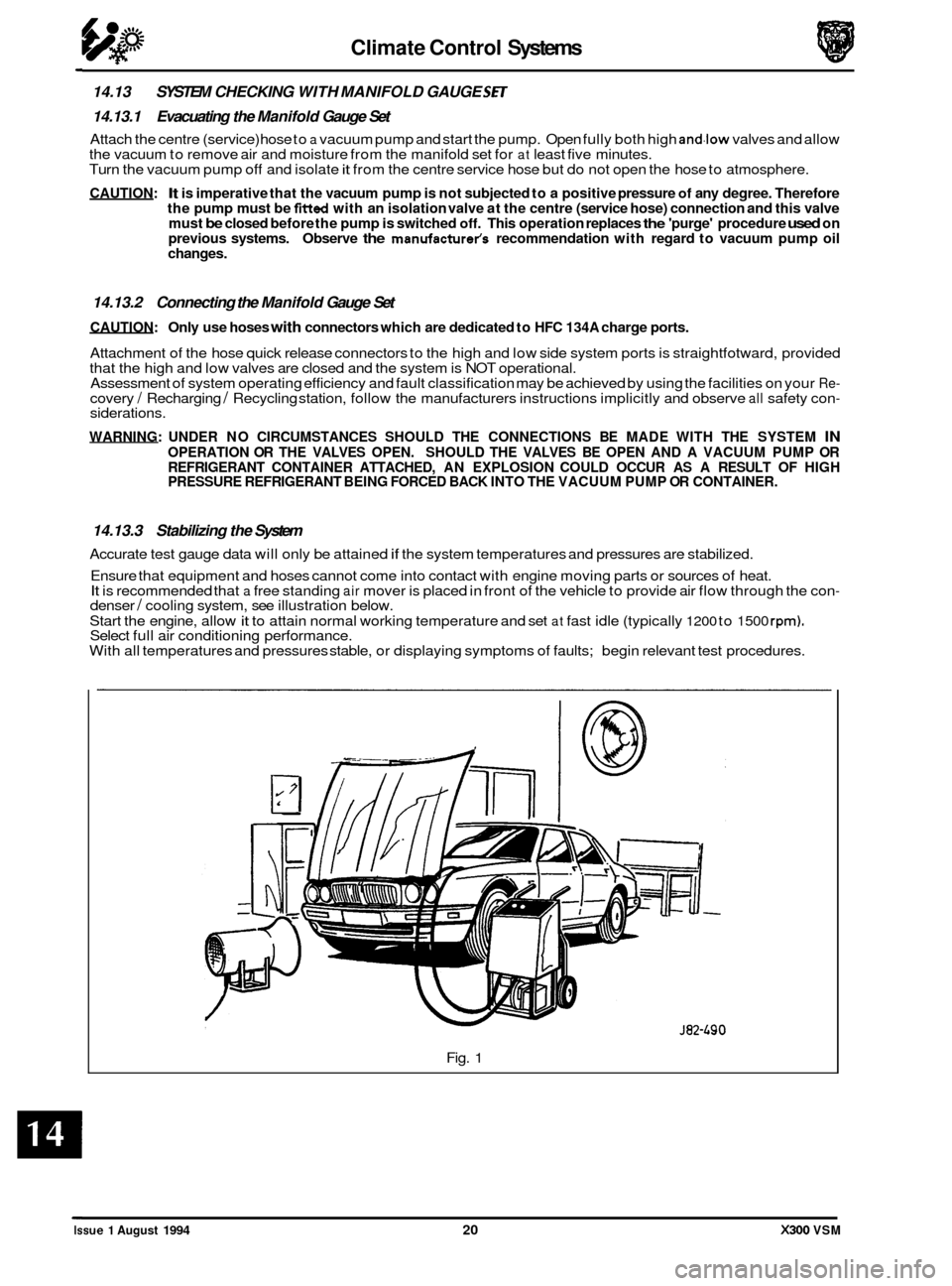
It is recommended that a free standing air mover is placed in front of the vehicle to provide air flow through the con- denser / cooling system, see illustration below.
Start the engine, allow
it to attain normal working temperature and set at fast idle (typically 1200 to 1500 rpm). Select full air conditioning performance.
With all temperatures and pressures stable, or displaying symptoms of faults; begin relevant test procedures.
Fig.
1
Issue 1 August 1994 20 X300 VSM
Page 336 of 521
Climate Control Systems
High Side Gauge
Normal
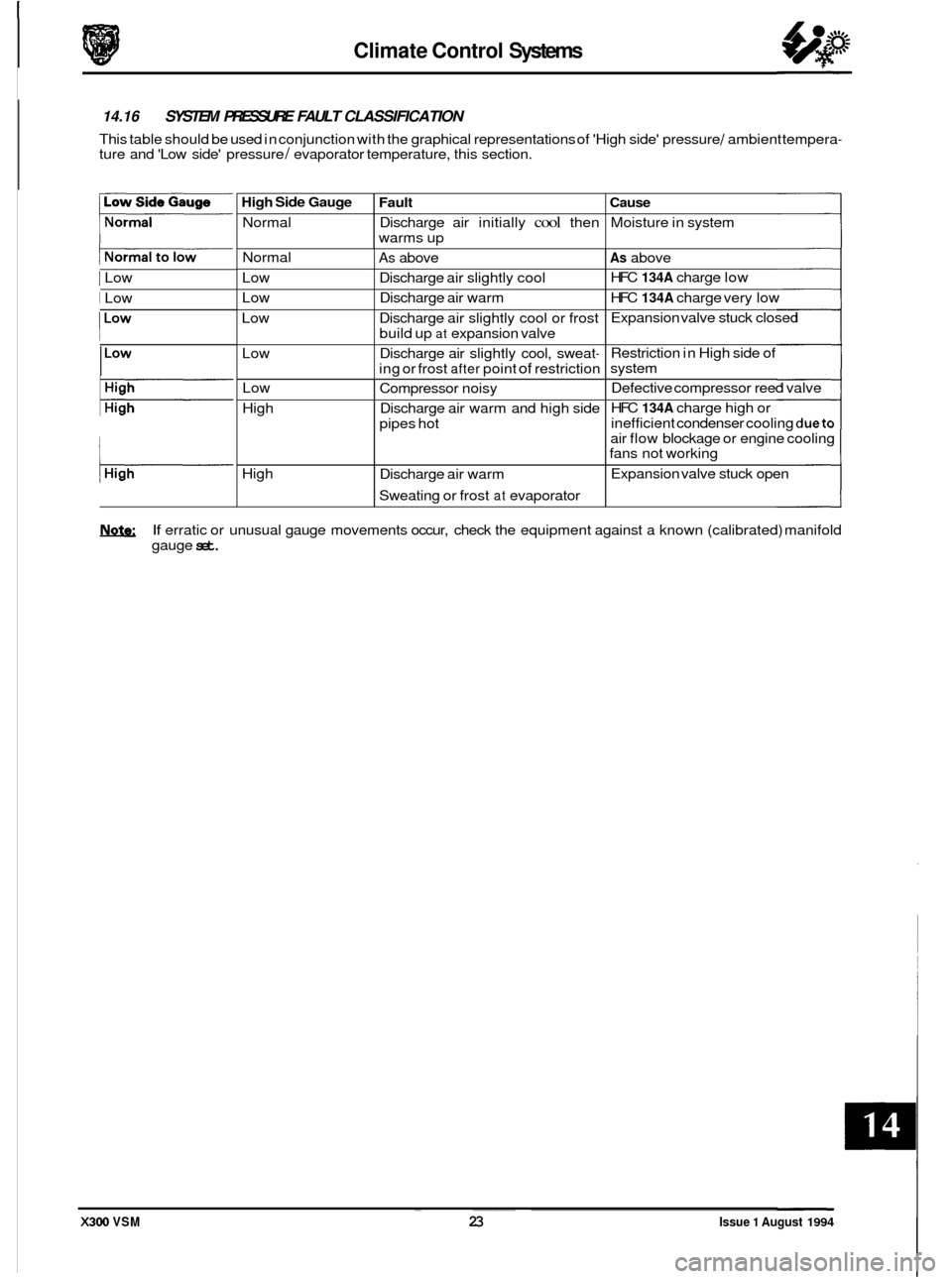
@ 14.16 SYSTEM PRESSURE FAULT CLASSIFICATION
This table should be used in conjunction with the graphical representations of 'High side' pressure / ambient tempera- ture and 'Low side' pressure / evaporator temperature, this section.
Fault Cause
Discharge air initially cool then Moisture in system
warms up
1 Low Normal
Low
Low
Low
Low
I Low
As above As above
Discharge air slightly cool HFC
134A charge
low
Discharge air warm HFC
134A charge very low
Discharge air slightly cool or frost Expansion valve
stuck closed
build up
at expansion valve
Discharge air slightly cool, sweat
- Restriction in High side of
ing or frost
after point of restriction system
I
Low
High
High
I
Compressor noisy Defective compressor
reed valve
Discharge air warm and high side HFC
134A charge
high or
pipes hot inefficient
condenser cooling
dueto
air flow blockage or engine cooling
fans not working
Expansion valve stuck open
Discharge air warm
Sweating or frost
at evaporator
If erratic or unusual gauge movements occur, check the equipment against a known (calibrated) manifold
gauge
set. ~ ~~~
X300 VSM 23 Issue 1 August 1994
Page 339 of 521
rl Electrical
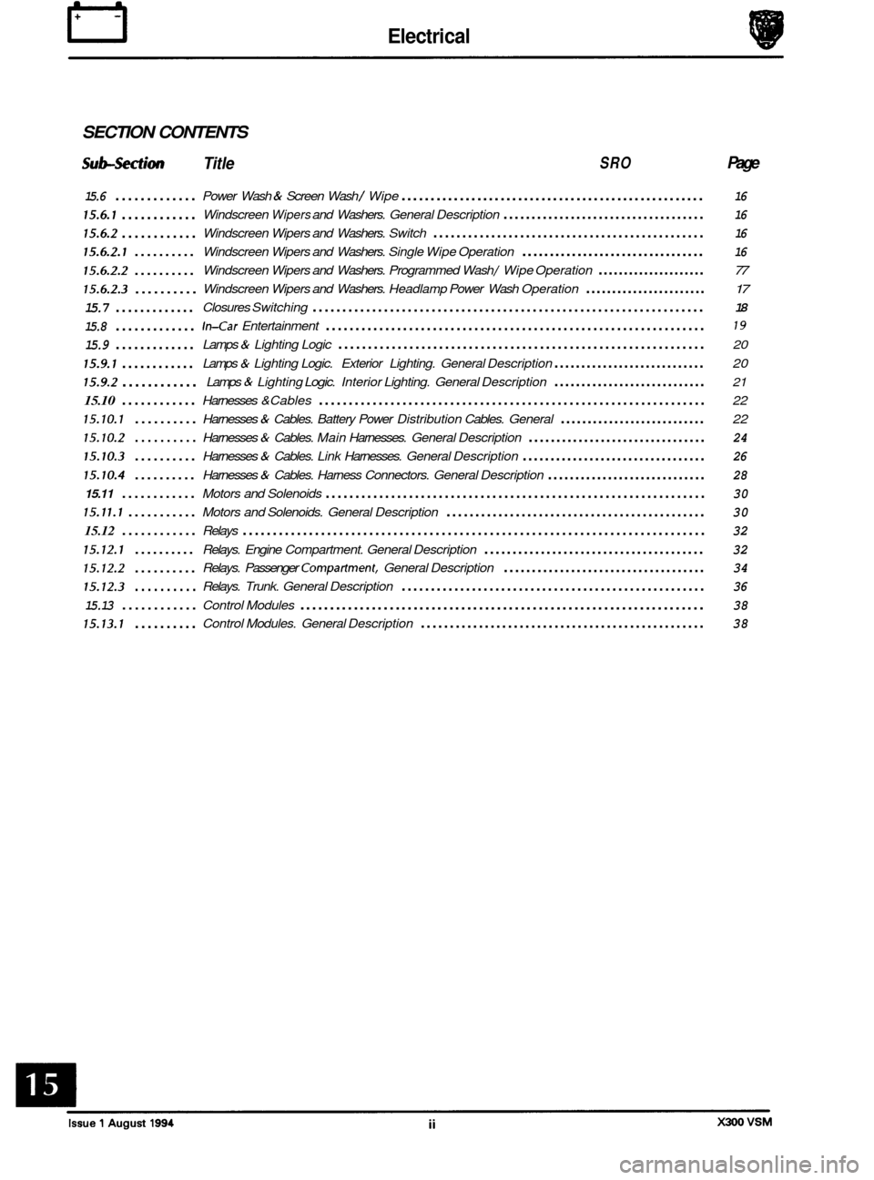
SECTION CONTENTS
Sub-section Title SRO Page
15.6 .............
15.6.1 ............
15.6.2 ............
15.6.2.1 ..........
15.6.2.2 ..........
15.6.2.3 ..........
15.7 .............
15.8 .............
15.9 .............
15.9.1 ............
15.9.2 ............
15.10 ............
15.10.1 ..........
15.10.2 ..........
15.10.3 ..........
15.10.4 ..........
15.11 ............
15.11.1 ...........
15.12 ............
15.12.1 ..........
15.12.2 ..........
15.12.3 ..........
15.13 ............
15.13.1 ..........
Power Wash & Screen Wash / Wipe .................................................... 16
Windscreen Wipers and Washers. General Description .................................... 16
Windscreen Wipers and Washers. Switch ............................................... 16
Windscreen Wipers and Washers. Single Wipe Operation ................................. 16
Windscreen Wipers and Washers. Programmed Wash / Wipe Operation ..................... 77
Windscreen Wipers and Washers. Headlamp Power Wash Operation ....................... 17
Closures Switching .................................................................. 18
In-Car Entertainment ................................................................ 19
Lamps & Lighting Logic .............................................................. 20
Lamps & Lighting Logic. Exterior Lighting. General Description ............................ 20
Lamps & Lighting Logic. Interior Lighting. General Description ............................ 21
Harnesses &Cables ................................................................. 22
Harnesses
& Cables. Battery Power Distribution Cables. General ........................... 22
Harnesses & Cables. Main Harnesses. General Description ................................ 24
Harnesses & Cables. Link Harnesses. General Description ................................. 26
Harnesses & Cables. Harness Connectors. General Description ............................. 28
Motors and Solenoids ................................................................ 30
Motors and Solenoids. General Description ............................................. 30
Relays ........................................................................\
..... 32
Relays. Engine Compartment. General Description ....................................... 32
Relays. Passenger Compartment. General Description .................................... 34
Relays. Trunk. General Description .................................................... 36
Control Modules .................................................................... 38
Control Modules. General Description ................................................. 38
Page 345 of 521
rl Electrical
15.1.6 Fire Hazard Infonnath
Thermal decomposition or combustion may produce dense smoke and other dangerous fumes which in fire situations
form
a highly toxic explosive.
In the event of fire the surrounding area must be evacuated and
all personnel kept well upwind of the area.
Full fire fighting protective gear and
a self contained breathing apparatus operating in the positive pressure mode must
be worn for combating fire. Material near fires must be cooled with water spray to prevent ignition.
Fires should be allowed to burn themselves
out if not threatening to life or property. If fire is threatening to life or prop- erty use copious quantities of water to extinguish.
15.1.7 Ventilath
Local exhaust ventilation designed by a professional engineer should be provided if vapours, fumes, or dusts are gen- erated whilst working with airbag module.
The latest issue of the manual for recommended practices on 'Industrial Ventilation' is available from the
ACGIH Com- mittee on Industrial Ventilation, PO Box 16153, Lansing, MI 48910, USA.
The need for local exhaust ventilation should be evaluated by a professional industrial hygienist.
15.1.8 Respiratory Precauth
To prevent the inhalation of dangerous fumes and dusts, an approved mask should be worn.
15.1.9 Eye Protection
Chemical protective goggles are recommended where there is a possibility of eye contact with the propellant.
Safety glasses with side shields are recommended for
all other operations.
15.1. I0 Protective Clothing
Approved protective gloves, overalls and shoes / boots should be worn.
15.1.1 1 Handling and Storage Precautions
Do not store airbag module near live electrical equipment or circuitry. Store in a dry environment at ambient tempera-
tures.
Good housekeeping and engineering practices should be employed to prevent the generation and accumulation of
dusts. Store in compliance with
all local state and federal regulations.
15.1.12 Driver And Passenger Airbag Modules Assembly / Removal / Service Instructions
Before starting work, ensure ignition switch is in 'IocK position, key is removed and negative terminal cable
is disconnected from the battery.
As the airbag is equipped with a back up power source and due to the risk of airbag being inadvertently
deployed, wait one minute or longer before starting work.
0 Disconnecting the battery cancels the memory for clock, radio, seats, mirrors, steering column and any other
components using battery power. Reset memory after work is completed.
0 Never use airbags from other vehicles, always use new parts.
0 After work is completed, reconnect battery and perform warning light check see diagnostic manual.
0 Never use electrical probes to check voltage or electrical resistance.
0 Disconnect the airbag before carrying out any work on, or in the vicinity of module, or when using electric weld- ing equipment.
0 Always ensure that battery negative has been disconnected for one minute or longer before commencing any
removal procedure.
EB
Issue 1 August 1994 4 X300 VSM
Page 349 of 521
Electrical rl
15.2 INSTRUMENTS
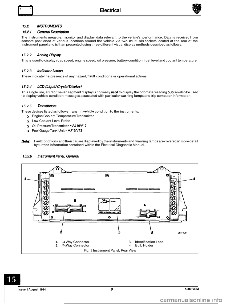
15.2.1 General Description
The instruments measure, monitor and display data relevant to the vehicle’s performance. Data is received from
sensors positioned at various locations around the vehicle via two multi-pin sockets located at the rear of the
instrument panel and is than presented using three different visual display methods described as follows:
15.2.2 Analog Display
This is used to display road speed, engine speed, oil pressure, battery condition, fuel level and coolant temperature.
15.2.3 Indicator Lamps
These indicate the presence of any hazard /fault conditions or operational actions.
15.2.4 LCD (Liquid Crystal Disp/ay)
This single line, six digit seven segment display is normally used to display the odometer reading but can also be used
to display vehicle condition messages associated with particular warning lamps and trip computer information.
15.2.5 Transducers
These devices listed as follows transmit vehicle condition to the instruments:
0 Engine Coolant Temperature Transmitter
0 Low Coolant Level Probe
0 Oil Pressure Transmitter - AJ16N12
0 Fuel Gauge Tank Unit - AJlW12
Fault conditions and their causes displayed by the instruments and warning lamps are covered in more detail
by further information contained within the
Electrical Diagnostic Manual.
15.2.6 Instrument Panel, General
2 I I 3 1
1. 24 Way Connector 3. Identification Label 2. 4% Way Connector 4. Bulb Holder
Fig.
1 Instrument Panel, Rear View
X300 VSM Issue 1 August 1994 8
c
Page 350 of 521
31
30
29
28 27
26
4 26 24 21 23 22 7 20 19 18 18 17 8
a
10
11
12
13
14
1s
1M-137
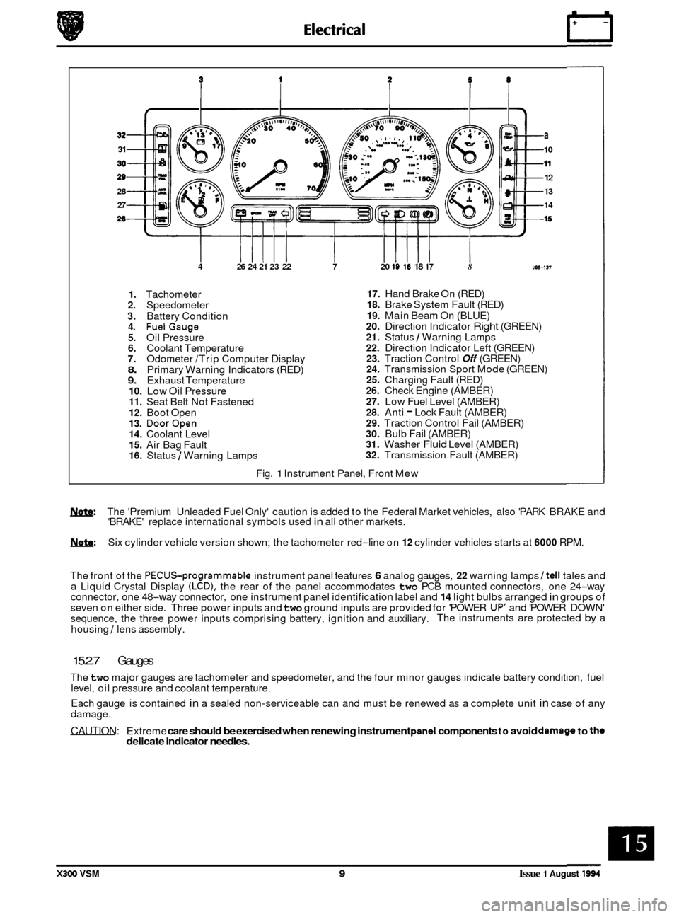
1. Tachometer 2. Speedometer
3. Battery Condition 4. FuelGauge 5. Oil Pressure 6. Coolant Temperature 7. Odometer /Trip Computer Display 8. Primary Warning Indicators (RED) 9. Exhaust Temperature 10. Low Oil Pressure 11. Seat Belt Not Fastened 12. Boot Open 13. DoorOpen 14. Coolant Level 15. Air Bag Fault 16. Status / Warning Lamps
17. Hand Brake On (RED) 18. Brake System Fault (RED)
19. Main Beam On (BLUE) 20. Direction Indicator Right (GREEN) 21. Status / Warning Lamps 22. Direction Indicator Left (GREEN) 23. Traction Control Off (GREEN) 24. Transmission Sport Mode (GREEN) 25. Charging Fault (RED) 26. Check Engine (AMBER)
27. Low Fuel Level (AMBER) 28. Anti - Lock Fault (AMBER) 29. Traction Control Fail (AMBER) 30. Bulb Fail (AMBER) 31. Washer Fluid Level (AMBER) 32. Transmission Fault (AMBER)
Fig.
1 Instrument Panel, Front Mew
w: The 'Premium Unleaded Fuel Only' caution is added to the Federal Market vehicles, also 'PARK BRAKE and
'BRAKE' replace international symbols used in all other markets.
m: Six cylinder vehicle version shown; the tachometer red-line on 12 cylinder vehicles starts at 6000 RPM.
The front of the
PECUSprogrammable instrument panel features 6 analog gauges, 22 warning lamps /tell tales and
a Liquid Crystal Display (LCD), the rear of the panel accommodates two PCB mounted connectors, one 24-way
connector, one 48-way connector, one instrument panel identification label and 14 light bulbs arranged in groups of
seven on either side. Three power inputs and two ground inputs are provided for 'POWER UP' and 'POWER DOWN'
sequence, the three power inputs comprising battery, ignition and auxiliary. The instruments are protected by a
housing
/ lens assembly.
15.2.7 Gauges
The two major gauges are tachometer and speedometer, and the four minor gauges indicate battery condition, fuel
level, oil pressure and coolant temperature.
Each gauge is contained
in a sealed non-serviceable can and must be renewed as a complete unit in case of any
damage.
CAUTION: Extreme care should be exercised when renewing instrument pand components to avoid damago to the delicate indicator needles.
X300 VSM 9 Issue 1 August 1994
Page 357 of 521
15.6
15.6.1
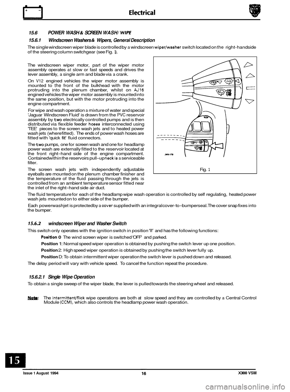
The single windscreen wiper blade is controlled by a windscreen wiper/washer switch located on the right-hand side
of the steering column switchgear (see Fig.
1).
POWER WASH & SCREEN WASH/ WlPE
Windscreen Washers & Wipers, General Description
The windscreen wiper motor, part of the wiper motor
assembly operates at slow or fast speeds and drives the
lever assembly, a single arm and blade via a crank.
On
V12 engined vehicles the wiper motor assembly is
mounted to the front of the bulkhead with the motor
protruding into the plenum chamber, whilst on AJ16 engined vehicles the wiper motor assembly is mounted into
the same position, but with the motor protruding into the
engine compartment.
For wipe and wash operation
a mixture of water and special
'Jaguar Windscreen Fluid' is drawn from the PVC reservoir
assembly by
two electrically controlled pumps and is then
distributed via flexible feeder hoses interconnected using
'TEE' pieces to the screen wash jets and to heated power
wash jets (where fitted). The ends of power wash hoses are
fitted with 'quick
fit' fluid connectors.
The
two pumps, one for screen wash and one for headlamp
power wash are externally fitted to the reservoir located at
the front right
-hand side of the engine compartment.
Contained within the reservoirs pull-up neckis a serviceable
filter.
The screen wash jets with independently adjustable
eyeballs are mounted on the plenum chamber finisher and
the temperature of the fluid passing through the jets is
controlled from an ambient temperature sensor fitted near
the inlet of the right
-hand side air duct. Fig.
1
The
fluid temperature for each of the headlamp wipe wash operation is controlled by self regulating, heated power
wash jets mounted on to either side of the bumper.
Each powerwash jet is protected by
a cover supplied with an integral cover-to-bumperseal. The cover snap fixes into
the bumper.
15.6.2
This switch only operates with the ignition switch in position '11' and has the following functions:
windscreen Wiper and Washer Switch
Position 0 The wind screen wiper is switched 'OFF' and parked.
Position 1: Normal speed wiper operation is obtained by pushing the switch lever up one position.
Position 2: High speed wiper operation is obtained by pushing the switch lever fully up.
Position D: To obtain intermittent wiper operation the switch lever is pushed down and released.
The delay period will vary with vehicle speed. To cancel the function repeat the procedure.
15.6.2.1 Single Wipe Operation
To obtain a single sweep of the wiper blade, the lever is pulled towards the steering wheel and released.
W The intermittenmick wipe operations are both at slow speed and they are controlled by a Central Control
Module (CCM), which also controls the headlamp power wash operation.
Issue 1 August 1994 X300 VSM
Page 364 of 521
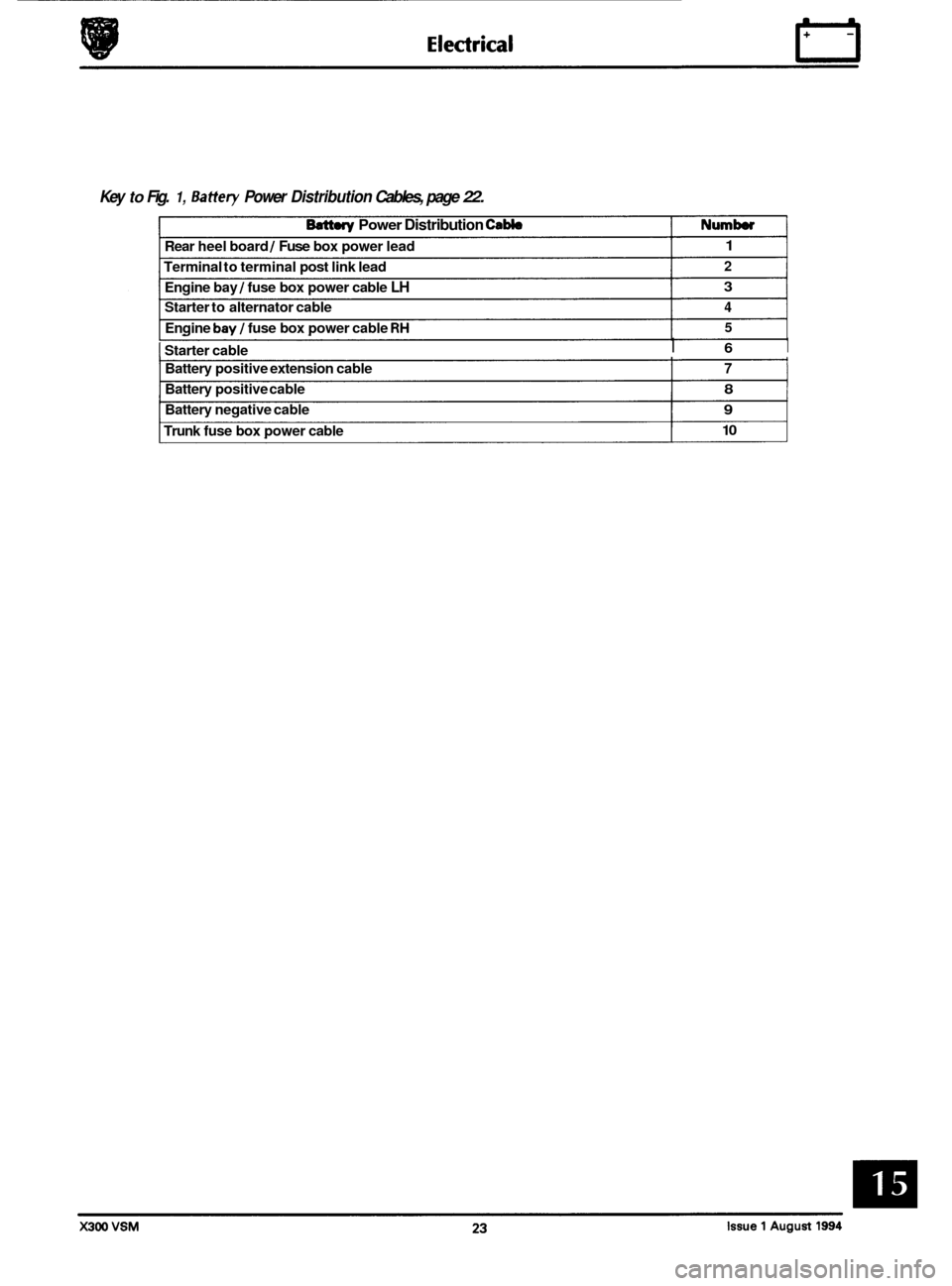
Key to Fig. 1, Battery Power Distribution Cables, page 22.
Rear heel board 1 Fuse box power lead 1
Terminal to terminal post link lead 2
Engine bay 1 fuse box power cable LH 3
Starter to alternator cable 4
Engine bay 1 fuse box power cable RH 5
Batt.ry Power Distribution Cabb Numb
1 Starter cable I 6 I
Battery positive extension cable 7
Battery positive cable 8
Battery negative cable 9
Trunk fuse box power cable 10
Page 365 of 521
IT E I ectr ical
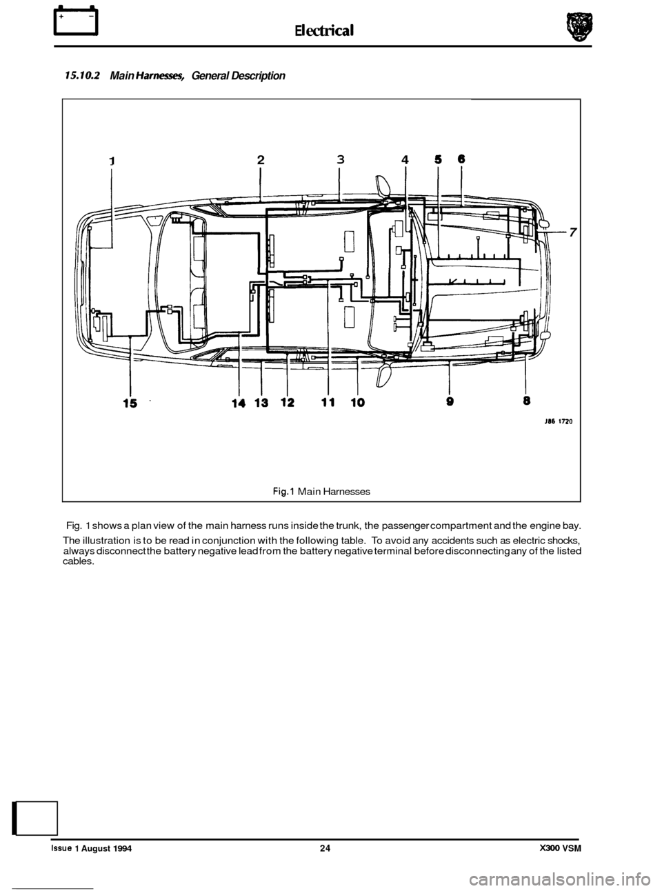
15.10.2 Main Harnm, General Description
1 2 3 4 56
7
M6 1720
Fig.1 Main Harnesses
Fig.
1 shows a plan view of the main harness runs inside the trunk, the passenger compartment and the engine bay.
The illustration is to be read in conjunction with the following table.
To avoid any accidents such as electric shocks,
always disconnect the battery negative lead from the battery negative terminal before disconnecting any of the listed
cables.
e
0
0
0
Issue 1 August 1994 24 X300 VSM
Page 367 of 521
rl Electrical
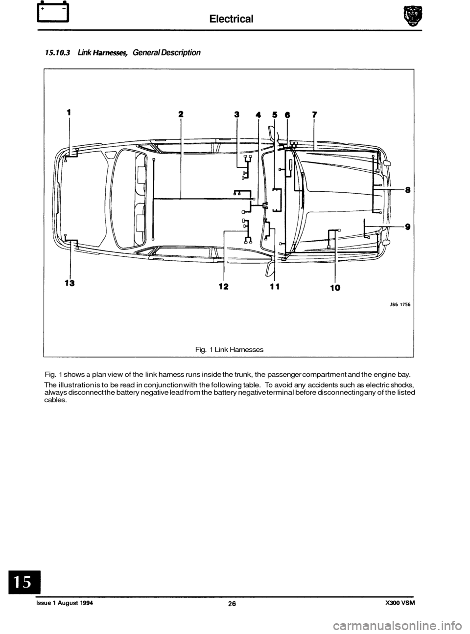
'5.10.3 Link /farnest?$, General Description
Fig. 1 Link Harnesses
Fig.
1 shows a plan view of the link harness runs inside the trunk, the passenger compartment and the engine bay.
The illustration is to be read in conjunction with the following table.
To avoid any accidents such as electric shocks,
always disconnect the battery negative lead from the battery negative terminal before disconnecting any of the listed
cables.