engine JAGUAR XJ6 1994 2.G Repair Manual
[x] Cancel search | Manufacturer: JAGUAR, Model Year: 1994, Model line: XJ6, Model: JAGUAR XJ6 1994 2.GPages: 521, PDF Size: 17.35 MB
Page 97 of 521
Fuel, Emission Control & Engine Management (V12)
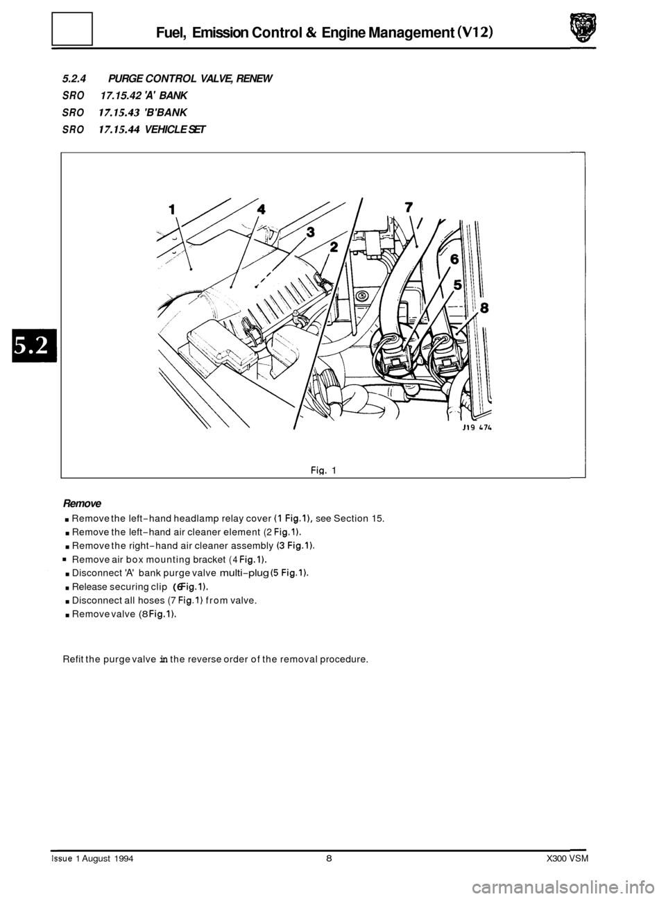
5.2.4 PURGE CONTROL VALVE, RENEW
SRO 17.15.42 'A' BANK
SRO 17.15.43 'B'BANK
SRO 17.15.44 VEHICLE SET
Fig. 1
Remove
. Remove the left-hand headlamp relay cover (1 Fig.l), see Section 15.
. Remove the left-hand air cleaner element (2 Fig.1).
. Remove the right-hand air cleaner assembly (3 Fig.1).
Remove air box mounting bracket (4 Fig.1).
. Disconnect 'A' bank purge valve multi-plug (5 Fig.1).
. Release securing clip (6 Fig.1).
. Disconnect all hoses (7 Fig.1) from valve.
. Remove valve (8 Fig.1).
Refit the purge valve in the reverse order of the removal procedure.
Issue 1 August 1994 8 X300 VSM
Page 98 of 521
Fuel, Emission Control & Engine Management (V12) ~~ ~
5.2.5
SRO
18.30.74 VEHICLE SET
IDLE SPEED CONTROL VALVE/ GASKETS, RENEW
SRO
18.30.73 VALVE- RIGHT HAND
SRO 18.30.76 GASKET
- RIGHT HAND
SRO
SRO 18.30.75 GASKET- LEFT HAND
18.30.72
VALVE
- LEFT HAND
Remove
. Disconnect battery.
. Drain coolant from radiator, see Section 4.2.
. Disconnect idle speed control valve multi-plug.
Disconnect all hoses linked to the idle speed control valve.
. Remove valve.
. Remove gasket.
Refit in the reverse order of the removal procedure.
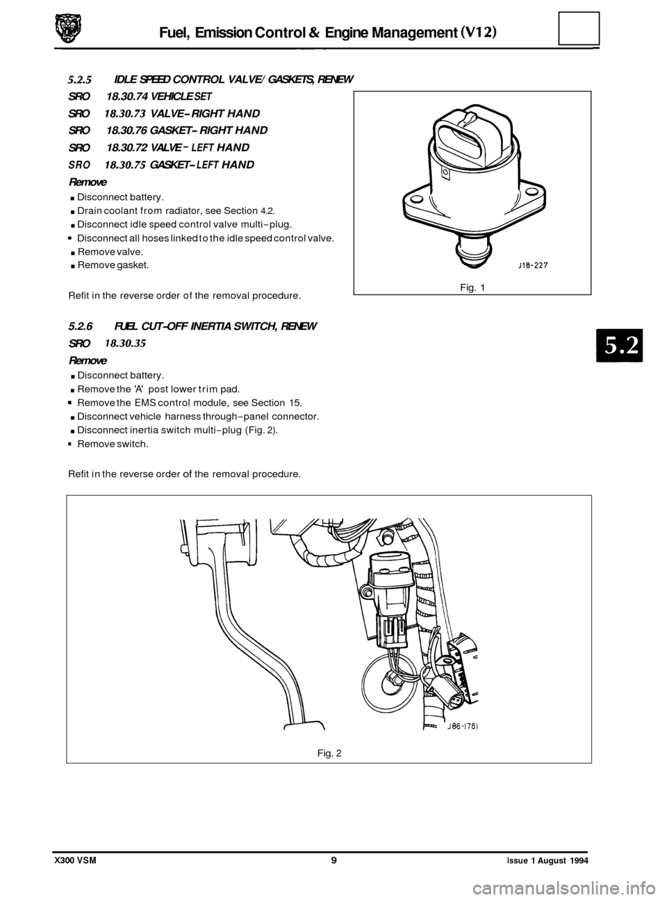
5.2.6 FUEL CUT-OFF INERTIA SWITCH, RENEW
SRO
18.30.35
Remove
. Disconnect battery.
. Remove the 'A' post lower trim pad.
= Remove the EMS control module, see Section 15.
. Disconnect vehicle harness through-panel connector.
. Disconnect inertia switch multi-plug (Fig. 2).
9 Remove switch.
Refit in the reverse order
of the removal procedure. Fig.
1
Fig. 2
X300 VSM 9 Issue 1 August 1994
Page 104 of 521
Exhaust System (AJ16)
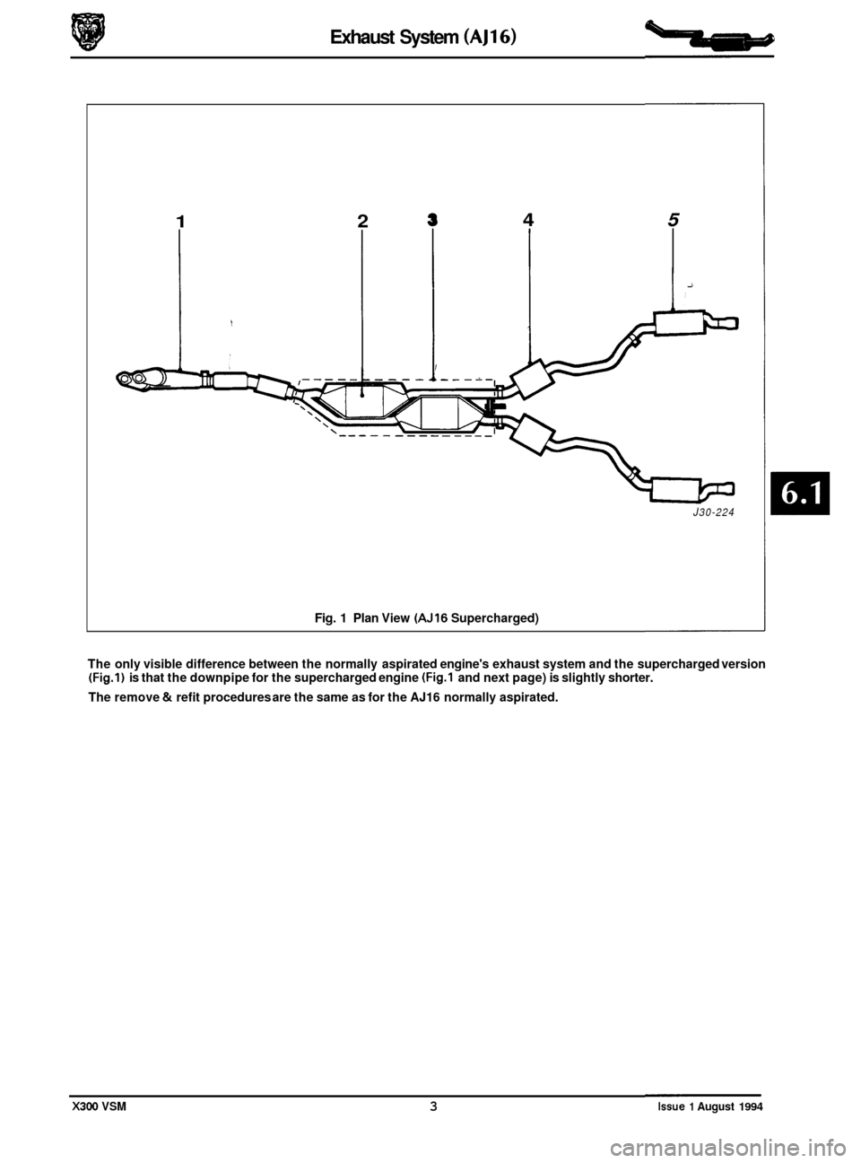
1 2
Fig. 1 Plan View (AJ16 Supercharged)
4 5
i
J30-224
The only visible difference between the normally aspirated engine's exhaust system and the supercharged version (Fig.1) is that the downpipe for the supercharged engine (Fig.1 and next page) is slightly shorter.
The remove
& refit procedures are the same as for the AJ16 normally aspirated.
X300 VSM 3 Issue 1 August 1994
Page 106 of 521
Also look for loose and rusted flange connections, loose or damaged exhaust shields
or clamp and loose or broken exhaust outlet pipe brackets.
6.1.2.1 Symptom Chart
I Condition I Possible Cause
Noises and exhaust fumes Exhaust leak.
Misaligned exhaust.
Loose clamps or fasteners.
Restricted exhaust system.
Electronic engine controls.
Fuel System.
Restricted exhaust system.
Engine lacking
power Ignition system.
Exhaust System (AJ16)
6.1.2 DIAGNOSIS AND TESTING
m: THE NORMAL OPERATING TEMPERATURE OF THE EXHAUST SYSTEM IS VERY HIGH. NEVER ATTEMPT
TO SERVICE ANY PART OF THE SYSTEM UNTIL IT HAS COOLED. EXHAUST GASES CONTAIN CARBON
MONOXIDE WHICH CAN BE HARMFUL TO HEALTH AND ARE POTENTIALLY LETHAL. LEAKS MUST BE
REPAIRED IMMEDIATELY.
NEVER OPERATE THE ENGINE
IN ENCLOSED AREAS.
External leaks in the exhaust system are often accompanied by noises and exhaust fumes, therefore a visual inspection
usually detects the location of the leak. When checking for exhaust leakage or noise, inspect the entire system for
burned
-out holes, loose or corroded clamps, muffler or exhaust inlet pipe.
Examine the under body for greyish
-white or black exhaust soot which indicates the exhaust leakage at that point.
The effect of a small leak can be magnified by holding a rag over the tailpipe outlet while listening to the leak.
If this is carried out, ensure that gases are not inhaled
-see WARNING.
When testing for a rattle or vibration condition it is helpful to use a rubber mallet. Tap on the exhaust components to
simulate the bouncing action of the exhaust while watching for exhaust-to-body /chassis contact.
6.1.2.2 Test A, Exhaust Leakage or Noise
Test Step
Step
1A Clamps and Brackets
Check for broken or loose clamps and/or exhaust
outlet pipe frame brackets.
Are clamps and exhaust outlet pipe frame brackets
OK?
Step 2A System Components
Check catalytic converters, muffler.
Are system components OK?
Step 3A Exhaust Manifold
Inspect exhaust manifold for loose fasteners and
cracks.
Is exhaust manifold OK?
Action
Refer to Test Step 1A.
Go to Test Step IB, Restricted exhaust system test. .-
Go to Test Step 1B
Result Action
yes
1
Go to Step 2A
no Service and renew as necessary.
Restart engine.
If noise still exists
go to Step 2
yes Go to step 3A
no Renew exhaust outlet pipe frame brackets, exhaust
inlet pipe and/ or muffler as necessary.
If noise still persists, go to Step 3
yes
no Go to Test Step 1B Restricted exhaust system test.
Tighten fasteners or renew exhaust manifold.
X300 VSM 5 Issue 1 August 1994
Page 107 of 521
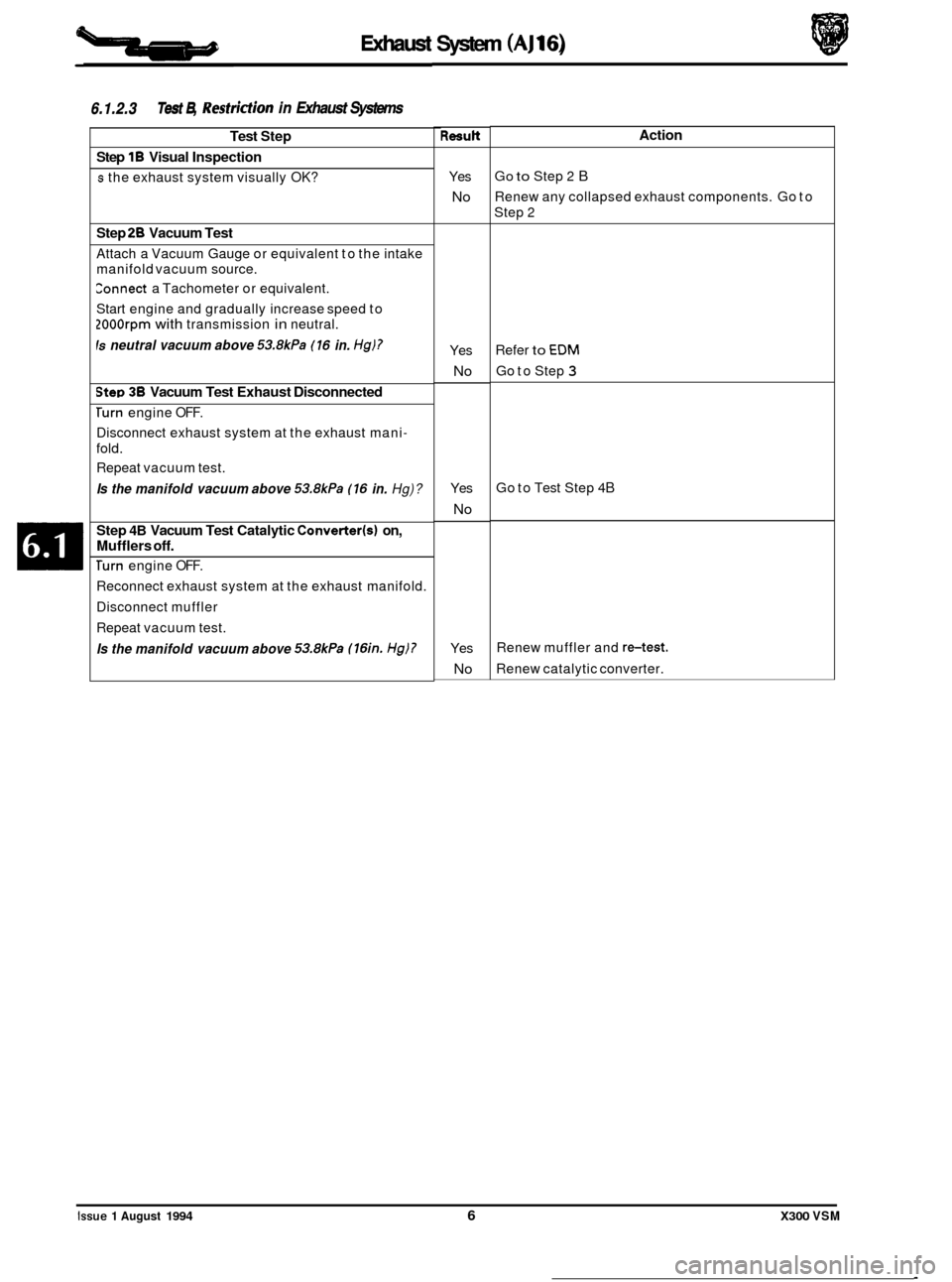
Exhaust
ridion in Exhaust Systems
Test Step
Step
1B Visual Inspection
s the exhaust system visually OK?
Step 28 Vacuum Test
Attach a Vacuum Gauge or equivalent to the intake
manifold vacuum source.
Eonnect a Tachometer or equivalent.
Start engine and gradually increase speed to
2OOOrpm with transmission in neutral.
Is neutral vacuum above 53.8kPa (16 in. Hg)?
Step 38 Vacuum Test Exhaust Disconnected
rurn engine OFF.
Disconnect exhaust system at the exhaust mani-
fold.
Repeat vacuum test.
Is the manifold vacuum above 53.8kPa (16 in. Hg)?
Step 4B Vacuum Test Catalytic Converter(s1 on,
Mufflers off.
+
6.1.2.3 Test B, Rest1
Turn engine OFF.
Reconnect exhaust system at the exhaust manifold.
Disconnect muffler
Repeat vacuum test.
Is the manifold vacuum above 53.8kPa (16in. Hg)?
System (AJ 1 6)
Resutt
Yes
No
Yes
No
Yes
No
Yes
No
Action
Go to Step 2 B
Renew any collapsed exhaust components. Go to
Step
2
Refer to EDM
Go to Step 3
Exhaust System (AJ16)
6.1.2.3 Test B, Restridion in Exhaust Systems
Go to Test Step 4B
Renew muffler and retest.
Renew catalytic converter.
Issue 1 August 1994 6 X300 VSM
Page 110 of 521
Exhaust System (V12)
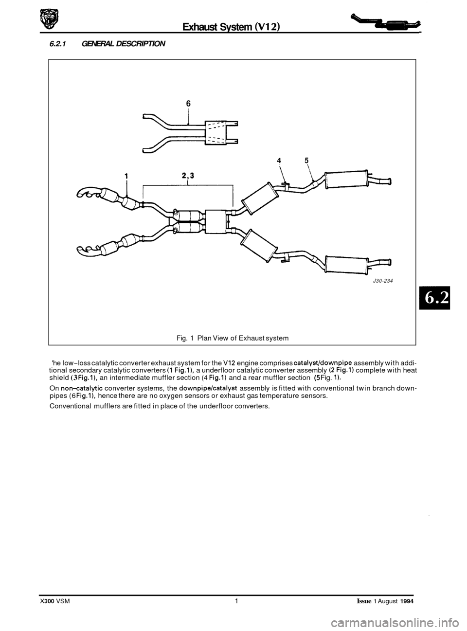
6.2.1 GENERAL DESCRIPTION
6
4 5
J30-234
Fig. 1 Plan View of Exhaust system
'he low
-loss catalytic converter exhaust system for the VI2 engine comprises catalyst/downpipe assembly with addi- tional secondary catalytic converters (1 Fig.11, a underfloor catalytic converter assembly (2 Fig.1) complete with heat
shield (3 Fig.l), an intermediate muffler section (4 Fig.1) and a rear muffler section (5 Fig. 1).
On non-catalytic converter systems, the downpipe/catalyst assembly is fitted with conventional twin branch down- pipes (6 Fig.11, hence there are no oxygen sensors or exhaust gas temperature sensors.
Conventional mufflers are fitted in place of the underfloor converters.
X300 VSM 1 Issue 1 August 1994
Page 115 of 521
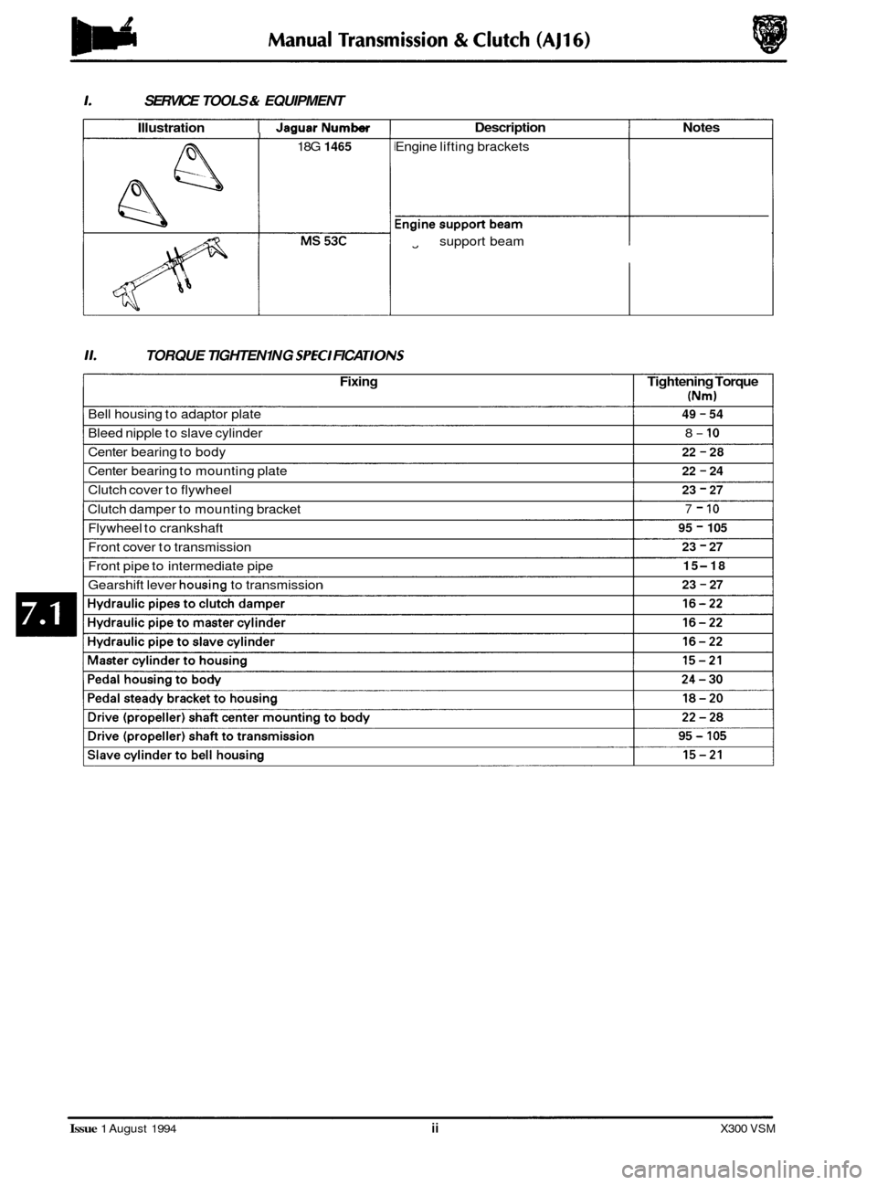
1. SERVICE TOOLS & EQUIPMENT
Illustration I JaauarNumber I -
18G 1465
Description Notes
Engine lifting brackets
Engine
fl support beam
11. TORQUE TIGHTEN1 NG SPEC1 FICA TIONS
Fixing Tightening Torque
(Nm)
49 - 54
8- 10
22 - 28
22
- 24
23 - 27
7 - 10
95 - 105
23
- 27
15
-18
23
- 27
Bell housing to adaptor plate
Bleed nipple to slave cylinder
Center bearing to body
Center bearing to mounting plate
Clutch cover to flywheel
Clutch damper to mounting bracket
Flywheel to crankshaft
Front cover to transmission
Front pipe to intermediate pipe
Gearshift lever
housing to transmission
Issue 1 August 1994 ii X300 VSM
Page 119 of 521
Manual Transmission & Clutch (AJ16)
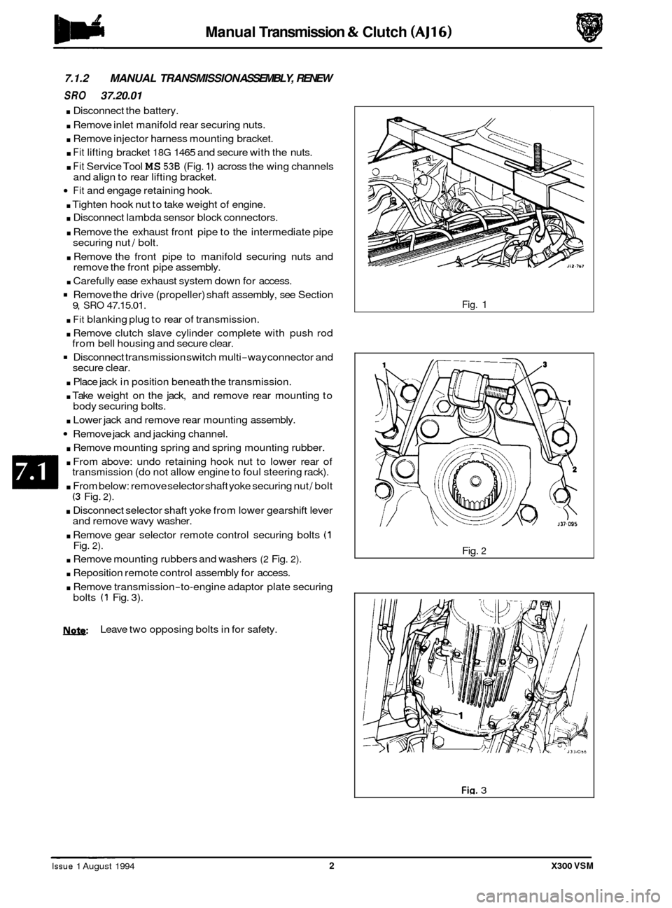
7.1.2 MANUAL TRANSMISSION ASSEMBLY, RENEW
SRO 37.20.01
. Disconnect the battery.
. Remove inlet manifold rear securing nuts.
. Remove injector harness mounting bracket.
. Fit lifting bracket 18G 1465 and secure with the nuts.
. Fit Service Tool MS 536 (Fig. 1) across the wing channels
Fit and engage retaining hook.
. Tighten hook nut to take weight of engine.
. Disconnect lambda sensor block connectors.
. Remove the exhaust front pipe to the intermediate pipe
securing nut / bolt.
. Remove the front pipe to manifold securing nuts and
remove the front pipe assembly.
. Carefully ease exhaust system down for access.
Remove the drive (propeller) shaft assembly, see Section
. Fit blanking plug to rear of transmission.
. Remove clutch slave cylinder complete with push rod
Disconnect transmission switch multi-way connector and
. Place jack in position beneath the transmission.
. Take weight on the jack, and remove rear mounting to
. Lower jack and remove rear mounting assembly.
Remove jack and jacking channel.
. Remove mounting spring and spring mounting rubber.
. From above: undo retaining hook nut to lower rear of
transmission (do not allow engine to foul steering rack).
. From below: remove selector shaft yoke securing nut / bolt (3 Fig. 2).
. Disconnect selector shaft yoke from lower gearshift lever
and remove wavy washer.
. Remove gear selector remote control securing bolts (1 Fig. 2).
. Remove mounting rubbers and washers (2 Fig. 2).
. Reposition remote control assembly for access.
. Remove transmission-to-engine adaptor plate securing
and
align to rear lifting bracket.
9, SRO 47.15.01.
from bell housing and secure clear.
secure clear.
body securing bolts.
bolts
(1 Fig. 3).
N.&: Leave two opposing bolts in for safety.
Fig. 1
Fig.
2
Fig. 3 ~ ~ ~~ ~
Issue 1 August 1994 2 X300 VSM
Page 120 of 521
Manual Transmission & Clutch (AJ16)
. Remove front clamp from unit lift.
. Raise / lower unit with jack, no stands.
. Traverse lift under ramp and take weight of transmission.
. Adjust jacking platform angles to suit transmission.
. Adjust side and rear clamps to suit transmission and tighten clamp wing nuts.
. Fit the safety chain assembly to left hand arm of lift, and secure with peg.
Pass safety chain over transmission and engage in front arm of lift. Tighten the safety chain adjuster.
. Remove remaining transmission to adaptor plate securing bolts and carefully lower transmission from engine.
. Remove transmission from ramp area.
. Remove clutch release bearing assembly from release lever.
. Remove clutch release lever retaining clip and remove lever.
. Remove release lever pivot pin.
Remove transmission switch.
. Remove rear mounting spring retainer securing nut.
. Reposition selector shaft pin cover.
0
Remove rear mounting spring retainer and remove rear mounting assembly.
Remove selector shaft yoke to selector shaft retaining pin and remove the yoke.
. Remove slave cylinder securing studs.
. Remove the transmission from the unit lift.
. Remove transmission drain plug and allow to drain, refit
the drain plug.
Fit new transmission to unit lift.
Fill transmission with oil and refit the level plug.
. Clean components and mating faces.
. Fit the slave cylinder mounting studs.
. Lubricate the selector output shaft.
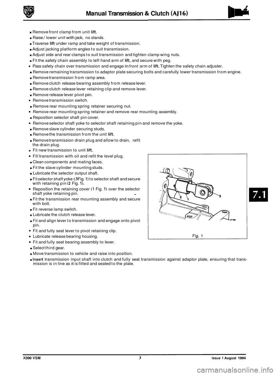
. Fit selector shaft yoke (3 Fig. 1) to selector shaft and secure
with retaining pin (2 Fig. 1).
Reposition the retaining cover (1 Fig. 1) over the selector
shaft yoke retaining pin. -
. Fit the transmission rear mounting assembly and secure
with bolt.
. Fit reverse lamp switch.
. Lubricate the clutch release lever.
. Fit and align lever to transmission and engage onto pivot
pin.
Fit and fully seat lever to pivot retaining clip.
= Lubricate release bearing housing.
9 Fit and fully seat bearing assembly to lever.
. Select third gear.
. Move transmission to vehicle and raise into position.
Fia. 1
. Insert transmission input shaft into clutch and fully seat transmission against adaptor plate, ensuring that trans- mission is in line as it is fitted and seated to the plate.
X300 VSM 3 Issue 1 August 1994
Page 124 of 521
Manual Transmission & Clutch (AJ16)
GEARSHIFT LEVER KNOB, RENEW
:RY 37.16.11
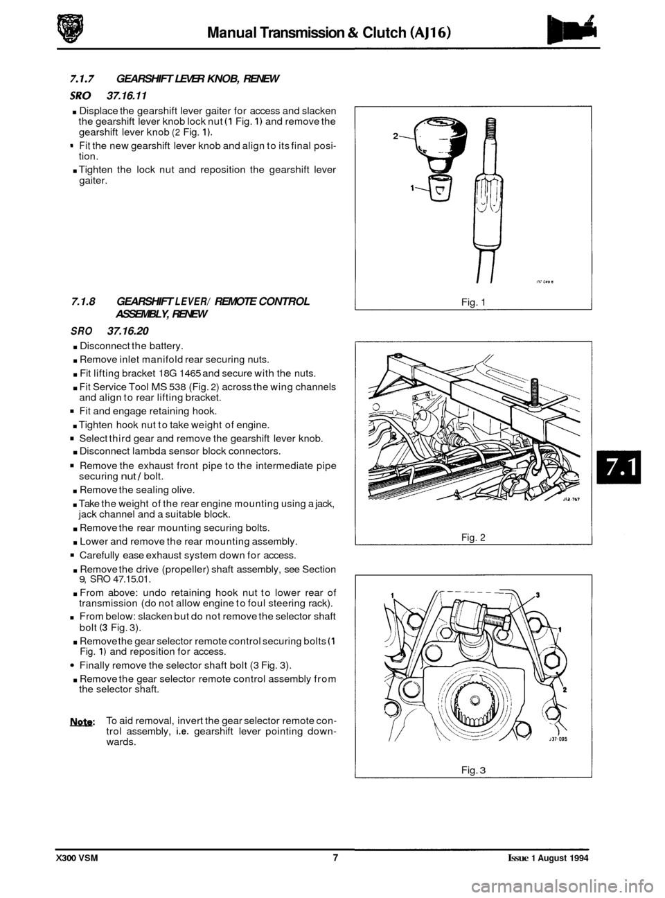
. Displace the gearshift lever gaiter for access and slacken
the gearshift lever knob lock nut (1 Fig. 1) and remove the
gearshift lever knob
(2 Fig. 1).
- Fit the new gearshift lever knob and align to its final posi- tion.
. Tighten the lock nut and reposition the gearshift lever
gaiter.
7.1.8 GEARSHIFT LEVER/ REMOTE CONTROL
ASSEMBLY, RENEW
SRO 37.16.20
. Disconnect the battery.
. Remove inlet manifold rear securing nuts.
. Fit lifting bracket 18G 1465 and secure with the nuts.
. Fit Service Tool MS 538 (Fig. 2) across the wing channels
and align to rear lifting bracket.
Fit and engage retaining hook.
. Tighten hook nut to take weight of engine.
Select third gear and remove the gearshift lever knob.
. Disconnect lambda sensor block connectors.
Remove the exhaust front pipe to the intermediate pipe
securing nut / bolt.
. Remove the sealing olive.
. Take the weight of the rear engine mounting using a jack,
. Remove the rear mounting securing bolts.
. Lower and remove the rear mounting assembly.
Carefully ease exhaust system down for access.
jack channel
and a suitable block.
. Remove the drive (propeller) shaft assembly, see Section 9, SRO 47.15.01.
. From above: undo retaining hook nut to lower rear of
transmission (do not allow engine to foul steering rack).
From below: slacken but do not remove the selector shaft
bolt
(3 Fig. 3).
. Remove the gear selector remote control securing bolts (1 Fig. 1) and reposition for access.
Finally remove the selector shaft bolt (3 Fig. 3).
. Remove the gear selector remote control assembly from
the selector shaft.
b: To aid removal, invert the gear selector remote con- trol assembly, i.e. gearshift lever pointing down- wards.
2
Fig. 1
Fig. 2
Fig. 3
X300 VSM 7 Issue 1 August 1994