engine JAGUAR XJ6 1994 2.G Workshop Manual
[x] Cancel search | Manufacturer: JAGUAR, Model Year: 1994, Model line: XJ6, Model: JAGUAR XJ6 1994 2.GPages: 521, PDF Size: 17.35 MB
Page 369 of 521

I3 Electrical
'5.10.4 Hamess Connecton, General Descriptbn
21
1 23 4 7 09
10
Fig. 1 Harness Connectors
Fig.
1 shows a plan view of the harness connectors physically linking all the harnesses located in the trunk, the passen- ger compartment and the engine bay.
The illustration
is to be read in conjunction with the following table. To avoid any accidents such as electric shocks,
always disconnect the battery negative lead from the battery negative terminal before disconnecting any of the listed
cables.
Page 371 of 521

15.11 MOTORS & SOLENOIDS ~
5.1 1.1 General
Description
Electrical
I# b
Fig. 1 Motors & Solenoids
-
1695
Fig. 1 shows a plan view of all motors located inside the trunk, the passenger compartment and the engine bay. The
motors drive various devices to perform certain functions such wipe / wash operations, window lift operations, seat
operations etc.
In order to carry out remove and refit operations, the annotated illustration is to be read in conjunction with the table
shown on the following page. This lists
all the motors and solenoids.
Some motors can be accessed by removing the various trims, the carpet, or carpet sections, other can be located
through carrying out
a visual inspection around the engine bay, the cab and the trunk.
To avoid any accidents such as electric shocks, always disconnect the battery negative lead from the battery negative
terminal before disconnecting any of the listed cables.
Issue 1 August 1994 30 X300 VSM
Page 373 of 521
rl Electrical
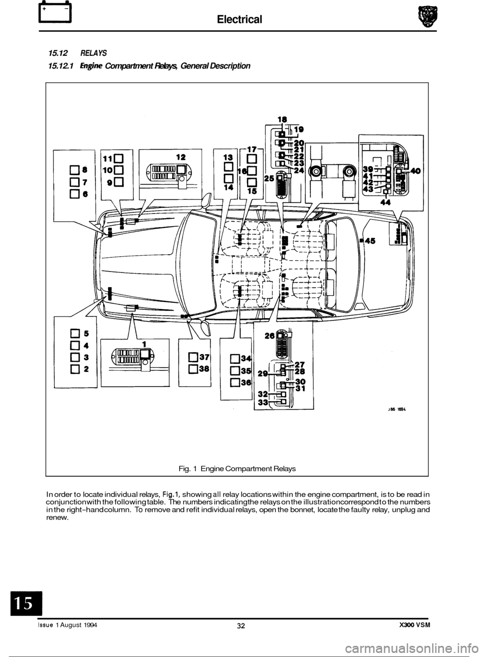
15.12 RELAYS
15.12.1 €@ne Compartment Relays, General Description
05
04
03
02
Fig. 1 Engine Compartment Relays
In order to locate individual relays,
Fig.1, showing all relay locations within the engine compartment, is to be read in
conjunction with the following table. The numbers indicating the relays on the illustration correspond to the numbers
in the right
-hand column. To remove and refit individual relays, open the bonnet, locate the faulty relay, unplug and
renew.
Issue 1 August 1994 32 X300 VSM
Page 374 of 521
Black
Black
Black All
models
All Models
All Models
Black
Black All
Models
All Models
Black/
White Stripe
Black/
White Stripe
Black Non
Aircon.
Models
only
Non Power
Wash Models
only
Optional
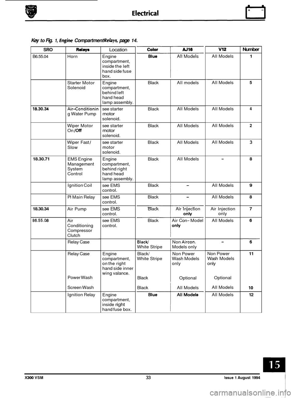
0 Key to Fig. 1, hgine Compartment Relays, page 14.
Number v12 Color
All Models
SRO
B6.55.04
Rdaw
Horn
Location
Engine
compartment,
inside the left
hand side fuse box.
Engine
compartment,
behind left hand head
lamp assembly.
see starter
motor
solenoid. All
Models
1 ~~
All
Models 5 Starter Motor
Solenoid
4 All Models
All Models 18.30.34 Air-conditionin
g Water Pump
Wiper Motor
On
/Off
2 see starter
motor
solenoid.
see starter
motor
solenoid. All
Models
3 Wiper Fast /
Slow
18.30.71 Engine
compartment, behind right
hand head
lamp assembly. 8 EMS Engine
Management
System
Control
Black
I
All Models 9 Ignition Coil
PI Main Relay see
EMS
control.
see EMS
control. Black
I
All
Models 8
Air Pump 7 see EMS
control.
see EMS
control. Black
Air Injection
Black Air Con
- Model Air
Injection
only
All Models
18.30.34
86.55.08 Air
Conditioning
Compressor
Clutch
Relay Case
Engine
compartment,
on the right
hand side inner
wing valance.
Relay
Case Non Power
Wash
Models
only
11
10
12
Power Wash
Screen Wash Optional
All Models
All Models
Black
All Models
Ignition Relay
Engine
compartment,
inside
right
hand fuse box.
X300 VSM 33 Issue 1 August 1994
Page 380 of 521
86.52.01
86.91 -83
19.75.21
86.80.24
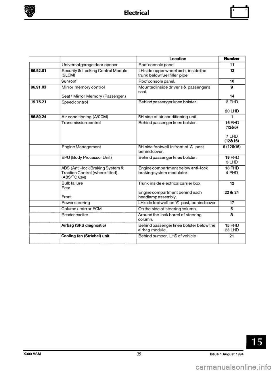
Universal garage door opener
Security
& Locking Control Module
(SLCM)
Sunroof
Mirror memory control
Seat
/ Mirror Memory (Passenger.)
Speed control
Air conditioning
(NCCM)
Transmission control
Engine Management
BPU (Body Processor Unit)
ABS (Anti
-lock Braking System &
Traction Control (where fitted).
(ABS/TC CM)
Bulb failure
Rear
Front
I Power steering
I Column / mirror ECM
Reader exciter
Location
Roof console panel
LH side upper wheel arch, inside the
trunk below fuel filler pipe
Roof console panel.
Mounted inside driver's
& passenger's
seat.
Behind passenger knee bolster.
RH side of air conditioning unit.
Behind passenger knee bolster.
RH side footwell in front of 'A' post
behind cover.
Behind passenger knee bolster.
Engine compartment below
anti-lock
braking system modulator.
Trunk inside electrical carrier box,
Engine compartment behind each
headlamp assembly.
LH side footwell on
'A' post, behind cover.
On the side of steering column.
Around the lock barrel of steering
column.
Behind passenger knee bolster below the
airbag module.
Behind bumper, LHS of vehicle
Numb
11
13
10
9
14
2
RHD
20 LHD
1
16
RHD
(1 2&6)
7 LHD
(12&16)
6 (12&16)
19 RHD
3 LHD
18 RHD
4 RHD
12
22
& 24
17 5
8
15 RHD
23 LHD
21
X300 VSM 39 issue 1 August 1994
Page 382 of 521
Snecif icat ion W -I- ..........
e
0
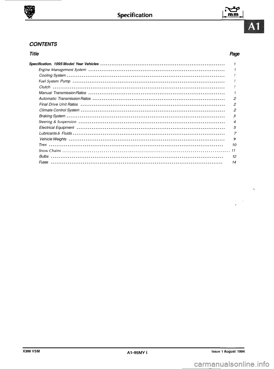
CON TENTS
Title Page
Specification. 1995 Model Year Vehicles ................................................................... 1
EngineManagementSystem ........................................................................\
. 1
Cooling System ........................................................................\
............ 7
Fuelsystem Pump ........................................................................\
......... 7
Clutch ........................................................................\
................... 7
Manual Transmission Ratios ........................................................................\
. 1
Automatic Transmission Ratios ....................................................................... \
2
Final Drive Unit Ratios ........................................................................\
..... 2
Climate Control System ........................................................................\
..... 2
Braking System ........................................................................\
............ 3
Steering&Suspension ........................................................................\
...... 4
Electrical Equipment ........................................................................\
....... 5
Lubricants & Fluids ........................................................................\
......... 7
Vehicle Weights ........................................................................\
........... 9
Tires ........................................................................\
.................... 10
Snowchains ........................................................................\
............. 17
Bulbs ........................................................................\
................... 12
Fuses ........................................................................\
................... 14
Issue 1 August 1994 AI-95MY i X300 VSM
Page 384 of 521
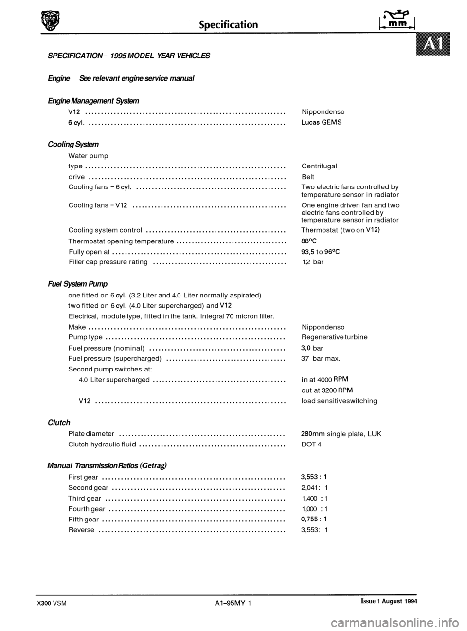
SPECIFICATION - 1995 MODEL YEAR VEHICLES
Engine See relevant engine service manual
Engine Management System
VI2 ............................................................... Nippondenso
6cyl. .............................................................. LucasGEMS
Cooling System
Water pump
type
............................................................... Centrifugal
Cooling fans
- 6 cyl. ................................................ Two electric fans controlled by
Cooling fans
- VI2 ................................................. One engine driven fan and two
Cooling system control
............................................. Thermostat (two on V12)
Thermostat opening temperature .................................... 88OC
Fully open at ....................................................... 93,5 to 96OC
Filler cap pressure rating ........................................... 1,2 bar
drive
.............................................................. Belt
temperature sensor in radiator
electric fans controlled by
temperature sensor
in radiator
Fuel System Pump
one fitted on 6 cyl. (3.2 Liter and 4.0 Liter normally aspirated)
two fitted on 6
cyl. (4.0 Liter supercharged) and VI2
Electrical, module type, fitted in the tank. Integral 70 micron filter.
Make
.............................................................. Nippondenso
Fuel pressure (nominal)
............................................ 3,O bar
Second
pump switches at:
Pump
type
......................................................... Regenerative turbine
Fuel pressure (supercharged)
....................................... 3,7 bar max.
4.0 Liter supercharged ........................................... in at 4000 RPM
out at 3200 RPM
VI2 ............................................................ load sensitiveswitching
Clutch
Plate diameter .....................................................
Clutch hydraulic fluid ............................................... DOT 4
280mm single plate, LUK
Manual Transmission Ratios (Gefragl
First gear .......................................................... 3,553:l
Second gear ....................................................... 2,041: 1
Third gear ......................................................... 1,400 : 1
Fourth gear
........................................................ 1,000 : 1
Fifth gear
.......................................................... 0,755:l
Reverse ........................................................... 3,553: 1
Issue 1 August 1994 X300 VSM AI-95MY 1
Page 390 of 521
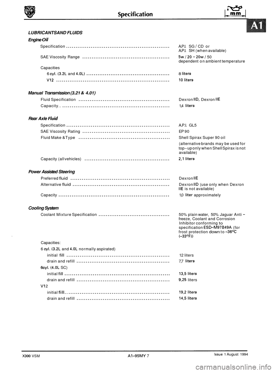
0 LUBRICANTSAND FLUIDS
Engine
Oil
Specification ....................................................... A.P.I. SG I CD or
A.P.I. SH (when available)
SAE Viscosity Range
............................................... 5w 120 - 20w J 50
dependent on ambient temperature
6 cyi. (3.2L and 4.0L) ............................................. 8 liters
VI2 ............................................................ 10liters
Capacities
Manual Transmission (3.21 & 4.01)
Fluid Specification ................................................. Dexron IlD, Dexron IIE
Capacity.. ......................................................... 1,4 liters
Rear Axle Fluid
Specification ....................................................... A.P.I. GL5
Fluid Make &Type
................................................. Shell Spirax Super 90 oil
SAE
Viscosity Rating
............................................... EP 90
(alternative brands may be used for
top
-up only when Shell Spirax is not
available)
0
Capacity (all vehicles) .............................................. 2,l liters
Power Assisted Steering
Preferred fluid ..................................................... Dexron IIE
Alternative fluid .................................................... Dexron IID (use only when Dexron IIE is not available)
Capacity
........................................................... 1,0 liter approximately
Cooling System
Coolant Mixture Specification ....................................... 50% plain water, 50% Jaguar Anti - freeze, Coolant and Corrosion
Inhibitor conforming to specification ESBM97B49A (for
frost protection down to -36OC (-33OF))
Capacities:
6
cyl. (3.2L and 4.OL normally aspirated)
initial
fill ....................................................... 12 liters
drain and refill
.................................................. 7,7 liters
6cyl. (4.0L SC)
initial
fill ........................................................ 13,5 liters
drain and refill .................................................. 9,25 liters
initial
fill.. ...................................................... 19,2 liters
drain and refill .................................................. 14,5 liters
VI 2
Issue 1 August 1994 X300 VSM AI-95MY 7
Page 395 of 521
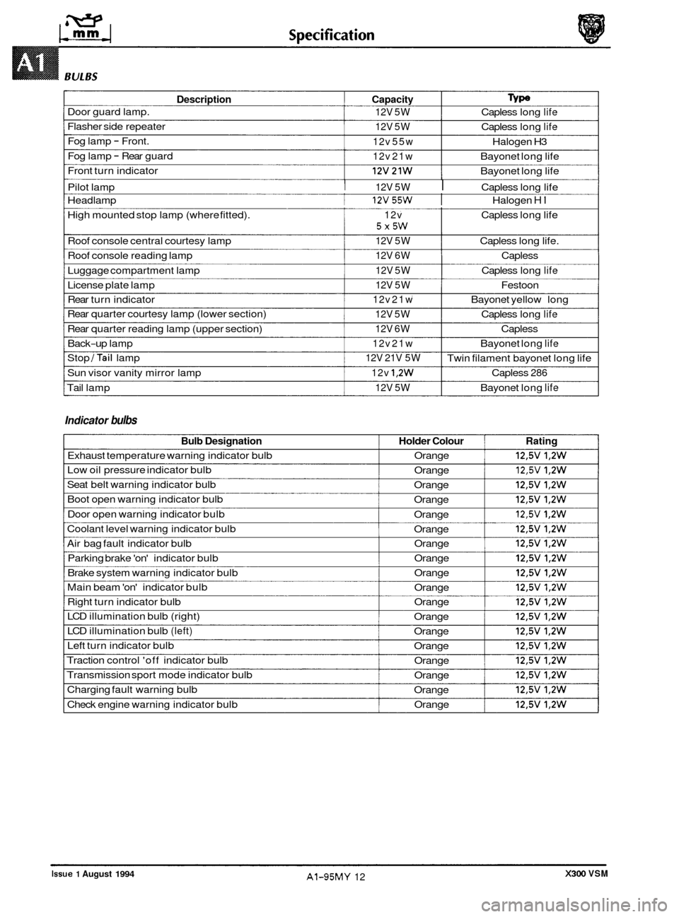
Description Capacity Type
Door guard lamp. 12V 5W Capless long life
Flasher side repeater 12V 5W Capless long life
Fog lamp - Front. 12v 55w Halogen H3
Fog lamp
- Rear guard 12v 21w Bayonet long life
Front turn indicator
I 12v21w I Bayonet long life
Pilot lamp
I 12V 5W I Capless long life
Headlamp
I 12v55w I Halogen HI
High mounted stop lamp (where fitted). 12v Capless long life
Roof console central courtesy lamp
12V 5W Capless long life.
Roof console reading lamp
12V 6W Capless
Luggage compartment lamp
12V 5W Capless long life
License plate lamp 12V 5W Festoon
Rear turn indicator
12v 21w Bayonet yellow long
Rear quarter courtesy lamp (lower section)
12V 5W Capless long life
Rear quarter reading lamp (upper section) 12V 6W Capless
Back
-up lamp 12v 21w Bayonet long life
Stop /Tail lamp
Sun visor vanity mirror lamp
12v 1,2w Capless 286
Tail lamp 12V 5W Bayonet long life
5X5W
12V 21V 5W Twin filament bayonet long life
Indicator bulbs
Bulb Designation Holder Colour Rating
Exhaust temperature warning indicator bulb Orange 12,5V 1,2W
Low oil pressure indicator bulb
Orange 12,5V 1,2W
Seat belt warning indicator bulb
Orange 12,5V 1,2W
Boot open warning indicator bulb
Orange 12,5V 1,2W
Door open warning indicator bulb
Orange 12,5V 1,2W
Coolant level warning indicator bulb
Orange 12,5V 1,2W
Air bag fault indicator bulb Orange 12,5V 1,2W
Parking brake 'on' indicator bulb Orange 12,5V 1,2W
Brake system warning indicator bulb Orange 12,5V 1,2W
Main beam 'on' indicator bulb
Orange 12,5V 1,2W
Right turn indicator bulb Orange 12,5V 1,2W
LCD illumination bulb (right)
Orange 12,5V 1,2W
LCD illumination bulb (left) Orange 12,5V 1,2W
Left turn indicator bulb
Orange 12,5V 1,2W
Traction control 'off indicator bulb
Orange 12,5V 1,2W
Transmission sport mode indicator bulb
Orange 12,5V 1,2W
Charging fault warning bulb
Orange 12,5V 1,2W
Check engine warning indicator bulb Orange 12,5V 1,2W
0
0
0
X300 VSM Issue 1 August 1994 AI-95MY 12
Page 397 of 521
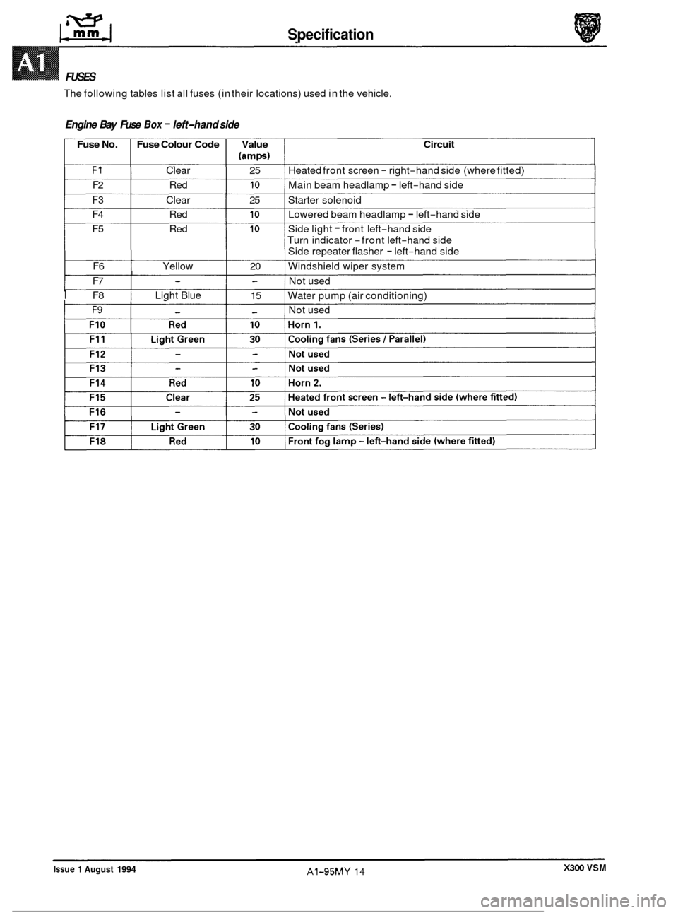
Specification
w IfrnrnJ
FUSES
The following tables list all fuses (in their locations) used in the vehicle.
Engine Bay Fuse Box - left-hand side
Fuse No. Fuse Colour Code Value Circuit
lamps)
F1 Clear 25 Heated front screen - right-hand side (where fitted)
F2 Red 10 Main beam headlamp - left-hand side
F3 Clear 25 Starter solenoid
F4 Red 10 Lowered beam headlamp - left-hand side
F5 Red 10 Side light - front left-hand side
Turn indicator
-front left-hand side
Side repeater flasher
- left-hand side
F6 Yellow 20 Windshield wiper system
I F8 I Light Blue
I Not used
F9 - - Not used
- - F7
15
Water pump (air conditioning) I - -
-l
X300 VSM Issue 1 August 1994 AI-95MY 14