tow JAGUAR XJ6 1994 2.G User Guide
[x] Cancel search | Manufacturer: JAGUAR, Model Year: 1994, Model line: XJ6, Model: JAGUAR XJ6 1994 2.GPages: 521, PDF Size: 17.35 MB
Page 263 of 521

13.2.18 Fuel Filler Flap, Description
The fuel filler flap comprises a hinged flap attached to the body decking panel by two M5 nuts; the flap incorporates
a rubber buffer, snap
-in striker, hinge spring and the fuel cap stowage magnet. The rubber fuel bowl moulding is at- tached via a steel armature to the body reinforcement panel by five M5 nuts and is retained at the filler neck by a clip.
The mating drain tube is fitted with an internal filter.
The fuel filler flap latch mechanism attached
tothe fuel bowl armature bytwo M5 nuts, includes a locking pin and actua- tor which are both serviceable items. The latch actuator operates independently from the central locking system; it is
driven directly
by the security and locking control module. Locking of the fuel filler flap is achieved only by operation
of the key or by the remote rf transmitter.
13.2.19 Filler Flap and Hinge, Renew
. Disconnect vehicle battery ground lead.
With filler cap open, remove hinge securing screws, fuel
. To refit, carry out reversal of the above procedure.
filler cap
and remove flap and hinge assembly.
13.2.20 Filler Cap Retention Magnet, Renew
. With filler flap open, use a blunt flat bladed implement and
CAUTION: Take care not to damage paintwork.
. To refit, carry out reversal of the above procedure.
Disconnect
vehicle battery ground lead.
remove the magnet assembly.
13.2.21 Filler Flap latching Assembly, Renew
. Disconnect vehicle battery ground lead.
. Depress the latching assembly retaining nut and remove
CAUTION: Take care not to damage paintwork.
. To refit, carry out reversal of the above procedure.
the
assembly.
1. Hingedflap 2. Striker 3. Hinge spring 4. Stowage magnet 5. Fuelbowl
Fig. 1 Fuel Filler Flap
X300 VSM Issue 1 August 1994 8
e
0
0
Page 301 of 521
Body Components & Trim a
13.7.4
Localized stains caused by accidental spillage may be one of three types:
0 Water based stainscaused byfoodstuffs,starches, sugars, soft drinks,fruit stains, washable inketc. These stains
adhere readily to the pile and do not respond to vacuum cleaning. They are best removed immediately using
the procedure detailed below.
0 Oil /grease based stains caused by spillage or other contamination by butter, grease, hand cream, ball point pen
ink, crayon, lipstick etc.
0 A combination of both these types.
Spot Cleaning - Localized Stains
To remove water based stains:
. Blot up liquids and /or scrape off semi-solids using a spatula.
. Sponge the affected area with clean luke-warm water. Use a clean, damp, undyed, cotton cloth to absorb as much
. If the stain persists, apply a suitable carpet shampoo solution made up to the manufacturers instructions, again work-
= Rinse with clean, warm water, taking care not to over-wet the carpet.
Absorb excess moisture by laying dry, undyed cloths or white paper towels over the moist carpet under light pres-
. When the carpet is thoroughly dry, vacuum clean the area to lift the carpet pile.
CAUTION: When liquids are applied to the pile, use only a clean cloth or sponge. Do not apply liquids directly to the
carpet - when attempting to remove stains, blot the pile as heavy rubbing can destroy the yarn structure of the carpet.
of the moisture as possible, working from the edge to the centre of the stain.
ing from the edge to the centre of the stain.
sure; replace when necessary.
To remove oil /grease based stains:
. Using a suitable aerosol containing solvent loaded with absorbent powder, spray the affected areas of the carpet.
= Allow the solvent to evaporate and remove the powder containing the grease by using a vacuum cleaner or brush.
m:
CAUTION: Solvents must only be used in well-ventilated areas where naked lights and smoking are prohibited.
The solvent loosens the grease from the fibre and the powder then absorbs the grease-carrying solvent.
Neat solvent, eg dry cleaning
fluid, may be used, but should be used sparingly from a clean white cloth.
To remove stains which are a combination of oil and water based contamination (usually resulting from food or drink):
. Treat combination stains as for water based stains.
. Allow to dry out.
. Treat as for grease based stains.
Issue 1 August 1994 46 X300 VSM
Page 304 of 521
Body Components & Trim
13.8.5
Renew
Front Seaf Head Restraint (Power Operated),
. Recline the seat to give access to the head restraint from
. Disengage the head restraint from its retainers with a
= To refit, carry out reversal of the above procedure, ensur-
the rear.
sharp upward
pull.
ing that the restraint is fully locked in position.
13.8.6 Rear Seaf Cushion, Renew
. Release the seat cushion quick release fittings.
. Remove the seat cushion from the vehicle.
To refit, carry out reversal of the above procedure.
13.8.7 Rear Seat Squab, Renew
. Release the rear seat cushion quick release fittings and re-
. Release the rear squab fixings and remove the squab.
. Move the rear seat belts aside and remove the squab as-
. Remove the armrest from the squab assembly.
. Remove the seat belt stowage pocket.
To refit, carry out reversal of the above procedure.
move
the cushion.
sembly from the vehicle.
Issue 1 August 1994 X300 VSM 49
Page 305 of 521
Body Components & Trim .Birpa,
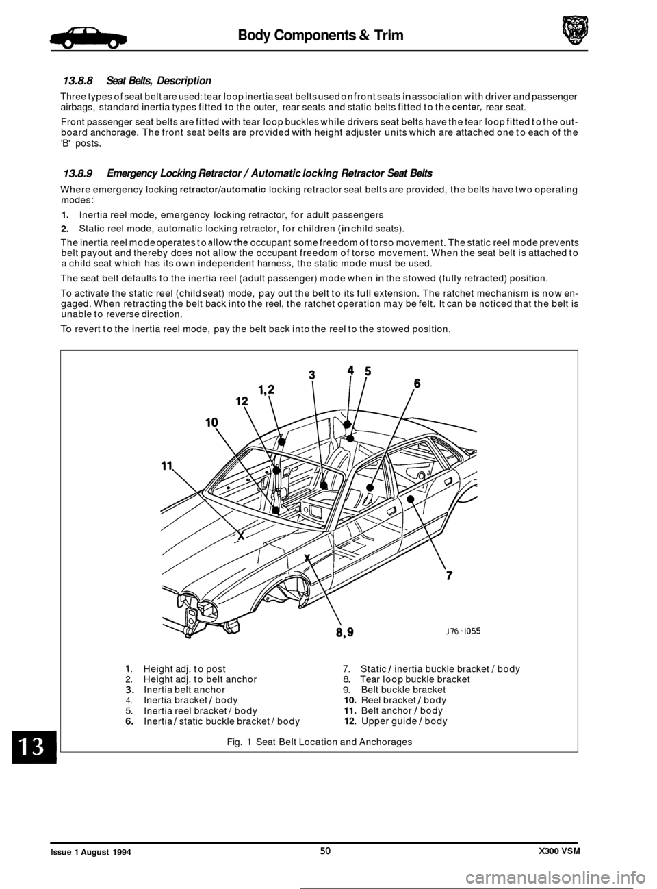
13.8.8 Seat Belts, Description
Three types of seat belt are used: tear loop inertia seat belts used on front seats in association with driver and passenger
airbags, standard inertia types fitted to the outer, rear seats and static belts fitted to the
center, rear seat.
Front passenger seat belts are fitted
with tear loop buckles while drivers seat belts have the tear loop fitted to the out- board anchorage. The front seat belts are provided with height adjuster units which are attached one to each of the
'B' posts.
13.8.9
Where emergency locking retractorlautomatic locking retractor seat belts are provided, the belts have two operating
modes:
1.
2.
The inertia reel mode operates to allowthe occupant some freedom of torso movement. The static reel mode prevents
belt payout and thereby does not allow the occupant freedom of torso movement. When the seat belt is attached to
a child seat which has its own independent harness, the static mode must be used.
The seat belt defaults to the inertia reel (adult passenger) mode when
in the stowed (fully retracted) position.
To activate the static reel (child seat) mode, pay out the belt to its
full extension. The ratchet mechanism is now en- gaged. When retracting the belt back into the reel, the ratchet operation may be felt. It can be noticed that the belt is
unable to reverse direction.
To revert to the inertia reel mode, pay the belt back into the reel to the stowed position.
Emergency Locking Retractor / Automatic locking Retractor Seat Belts
Inertia reel mode, emergency locking retractor, for adult passengers
Static reel mode, automatic locking retractor, for children
(in child seats).
1. Height adj. to post 7. Static 1 inertia buckle bracket I body 2. Height adj. to belt anchor 8. Tear loop buckle bracket 3. Inertia belt anchor 9. Belt buckle bracket 4. Inertia bracket / body 10. Reel bracket 1 body
5. 11. Belt anchor I body
6. 12. Upper guide I body
Inertia
reel bracket I body
Inertia 1 static buckle bracket I body
Fig.
1 Seat Belt Location and Anchorages
0
0
Issue 1 August 1994 50 X300 VSM
Page 306 of 521

Body Components & Trim
13.8.10 Tear loop Seat Belts, Description
The tear loop seat belt (Fig.1) is used to control the rate of forward travel of the occupant towards the deployed airbag
(the airbag is covered in Section 15, Electrical). The tear loop assembly is designed to release additional webbing when
the stitching, which retains the webbing loops, breaks under
a predetermined load. The wires (1 Fig. 1) within the as- sembly have the following functions:
0 To protect the stitching from 'normal' loads such as heavy braking or cornering.
o To control the rate of deployment.
0 To support the extended head following deployment.
When the passenger unit has been activated, the buckle will extend from the shroud and reveal
a warning label (2 Fig. 1); the extent of deployment will depend upon the severity of the load.
-: IF THE LABEL IS VISIBLE AT ALL (3 FIG. 3). THE COMPLETE ASSEMBLY MUST BE RENEWED, AS MUST
ANY SEAT BELT WHICH HAS BEEN WORN IN AN ACCIDENT.
2
Fia. 1 Tear LOOO Seat Belt
X300 VSM 51 Issue 1 August 1994 ~~
Page 357 of 521
15.6
15.6.1
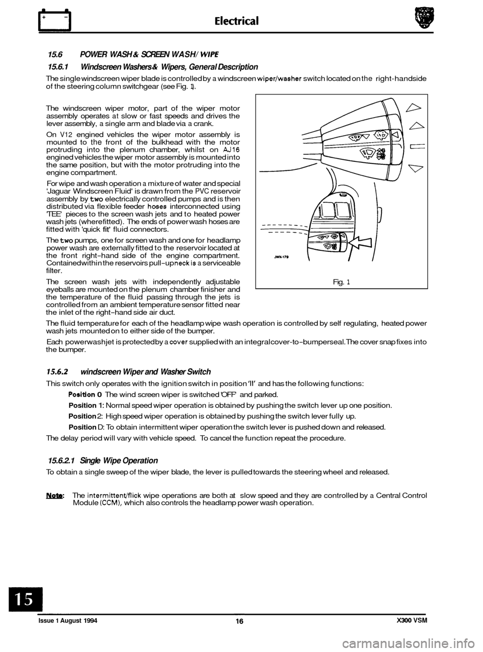
The single windscreen wiper blade is controlled by a windscreen wiper/washer switch located on the right-hand side
of the steering column switchgear (see Fig.
1).
POWER WASH & SCREEN WASH/ WlPE
Windscreen Washers & Wipers, General Description
The windscreen wiper motor, part of the wiper motor
assembly operates at slow or fast speeds and drives the
lever assembly, a single arm and blade via a crank.
On
V12 engined vehicles the wiper motor assembly is
mounted to the front of the bulkhead with the motor
protruding into the plenum chamber, whilst on AJ16 engined vehicles the wiper motor assembly is mounted into
the same position, but with the motor protruding into the
engine compartment.
For wipe and wash operation
a mixture of water and special
'Jaguar Windscreen Fluid' is drawn from the PVC reservoir
assembly by
two electrically controlled pumps and is then
distributed via flexible feeder hoses interconnected using
'TEE' pieces to the screen wash jets and to heated power
wash jets (where fitted). The ends of power wash hoses are
fitted with 'quick
fit' fluid connectors.
The
two pumps, one for screen wash and one for headlamp
power wash are externally fitted to the reservoir located at
the front right
-hand side of the engine compartment.
Contained within the reservoirs pull-up neckis a serviceable
filter.
The screen wash jets with independently adjustable
eyeballs are mounted on the plenum chamber finisher and
the temperature of the fluid passing through the jets is
controlled from an ambient temperature sensor fitted near
the inlet of the right
-hand side air duct. Fig.
1
The
fluid temperature for each of the headlamp wipe wash operation is controlled by self regulating, heated power
wash jets mounted on to either side of the bumper.
Each powerwash jet is protected by
a cover supplied with an integral cover-to-bumperseal. The cover snap fixes into
the bumper.
15.6.2
This switch only operates with the ignition switch in position '11' and has the following functions:
windscreen Wiper and Washer Switch
Position 0 The wind screen wiper is switched 'OFF' and parked.
Position 1: Normal speed wiper operation is obtained by pushing the switch lever up one position.
Position 2: High speed wiper operation is obtained by pushing the switch lever fully up.
Position D: To obtain intermittent wiper operation the switch lever is pushed down and released.
The delay period will vary with vehicle speed. To cancel the function repeat the procedure.
15.6.2.1 Single Wipe Operation
To obtain a single sweep of the wiper blade, the lever is pulled towards the steering wheel and released.
W The intermittenmick wipe operations are both at slow speed and they are controlled by a Central Control
Module (CCM), which also controls the headlamp power wash operation.
Issue 1 August 1994 X300 VSM
Page 414 of 521

in these areas indicates the onset of wear.
Hold the inner race between the fingers and thumb of one hand, spin the outer race and checkthat
it revolves absolutely
smoothly. Rotate the outer ring with a reciprocating motion, while holding the inner ring; feel for any obstruction to
rotation and reject the bearing if the action is not perfectly smooth. Lubricate the bearing generously with lubricant
appropriate to the installation. Inspect the shaft and bearing housing for discolouration or other marking which may
suggest that movement has taken place between the bearing and bearing seat.
If markings are found, use Loctite when
installing the replacement bearing.
Ensure that the shaft and housing
are clean and free from
burrs before fitting the bearing. If one bearing of a pair
shows an imperfection, it is generally advisable to renew
both bearings: an exception could be made only if the bear- ings had covered a low mileage and it could be established
that damage was confined to the one bearing.
- In the case of bearings which are lubricated with grease (e.g.
hub bearings) the space between the bearings should be
smeared with a recommended grade of grease, and the
bearings and seal should be re
-packed. When fitting the
bearing to the shaft, apply force only to the inner ring of
bearing (Fig.
1A). When fitting the bearing to the housing,
apply force only to outer ring (Fig. 1B).
Always mark components of separable bearings (e.g taper
roller bearings) when dismantling, to ensure correct
reassembly. Never
fit a new inner roller assembly to a used
outer track.
A3.2.6 Oil Seals
Always fit new oil seals when rebuilding an assembly.
Examine the seal before fitting to ensure that it is clean and
undamaged. Smear sealing lips with clean grease, pack
dust excluder seals with grease and pack grease into the
cavity between the sealing lips of duplex seals. Ensure that
the seal spring,
if provided, is correctly fitted.
Place the lip
of the seal towards the fluid to be sealed and
slide it into position on the shaft, using a fitting sleeve (Fig. 2) when possible to protect the sealing lip from damage by
threads, splines or sharp edges on the end of the shaft. If a fitting sleeve is not available, use plastic tube or adhesive
tape to prevent damage to the sealing lip.
Grease the outside diameter of the seal, place it square to the
housing recess and press it into position, using great care
and, where available, a seal installer (Fig. 3) to ensure that
the seal does not tilt. In some cases it may be preferable to
fit the seal to the housing before fitting it to the shaft. Never
let the weight of an unsupported shaft rest in a seal. If the
correct service tool is not available, use a piece of tube which
is approximately 0,4 mm (0.015 in) smaller than the outside
diameter of the seal. Use a press to install the seal or use a
hammer VERY GENTLY on the tubular drift if a press is un-
suitable or not available.
,107 001 A B
I Fig. 1
A3.2.5 Ball And Roller Bearings
CAUTION: Never replace a ball or roller bearing without first ensuring that it is in as-new condition.
Remove
all traces of lubricant from the bearing by washing it in petrol or a suitable degreaser. Maintain absolute
cleanliness throughout the operations. Inspect visually for markings of any form on rolling elements, bearing tracks,
outer surface of outer rings or inner surface of inner rings. Reject any bearings found to be marked, since any markings
Fig.
2
307 002
i
Fig. 3
Issue 1 August 1994 3 X300 VSM
Page 436 of 521
Body Systems
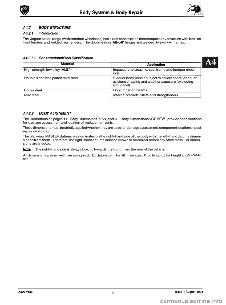
A4.2.1.1 Constructional Steel Classification
Material 1 dnnlirdiam I
High strength low alloy (HLSA).
Double sided zinc plated mild steel.
1 Boron steel
1 Mild steel.
A4.2.2 BODY ALIGNMENT
The illustrations on pages 11 - Body Dimensions PLAN, and 13 -Body Dimensions SIDE VIEW, provide specifications
for damage assessment and location of replacement parts.
These dimensions must be strictly applied whether they are used for damage assessment, component location or post
repair verification.
The plan view MASTER datums are nominated on the right
-hand side of the body with the left-hand datums dimen- sioned from them. Therefore, the right-hand datums must be known to be correct before any other cross-ar dimen- sions are checked.
W: The right-hand side is always looking towards the front, from the rear of the vehicle.
All dimensions are derived from a single
(ZERO) datum point for all three axes; X for length, Z for height and V cross- car.
Issue 1 August 1994 9 X300 VSM
A4.2 BODY STRUCTURE
A4.2.1
Introduction
The Jaguar sedan range (with standard wheelbase) has a unit construction monocoque body structure with bolt-on
front fenders and welded rear fenders. The doors feature 'lift-off' hinges and welded dropglass frames.
n@#pn.s..v..
Impact prone areas, ie. seat frame and bumper mount- ings.
Exterior body panels subject to severe conditions such
as stone chipping and weather exposure (excluding
roof panel).
Door intrusion beams
Internal brackets, fillets and strengtheners.
I
Page 485 of 521
Security System - RESTRICTED ISSUE 8-8
-
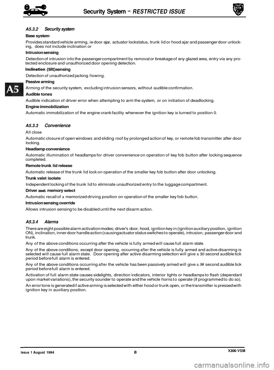
A5.3.2 Security system
Base system
Provides standard vehicle arming, ie door ajar, actuator lockstatus, trunk lid or hood ajar and passenger door unlock- ing, does not include inclination or
Intrusion sensing
Detection of intrusion into the passenger compartment by removal or breakage of any glazed area, entry via any pro- tected enclosure and unauthorized door opening detection.
Inclination (tilt) sensing
Detection of unauthorized jacking /towing.
Passive arming
Arming of the security system, excluding intrusion sensors, without audible confirmation.
Audible tones
Audible indication of driver error when attempting to arm the system, or on initiation of deadlocking.
Engine immobilization
Automatic immobilization of the engine crank facility whenever the ignition key is turned to position 0.
A5.3.3 Convenience
All close
Automatic closure of open windows and sliding roof by prolonged action of key, or remote fob transmitter after door
locking.
Headlamp convenience
Automatic illumination of headlamps for driver convenience on operation of key fob button after locking sequence
completed.
Remote trunk lid release
Automatic release of the trunk lid lock on operation of the smaller key fob button after door unlocking.
Trunk valet isolate
Independent locking of the trunk lid to eliminate unauthorized entry to the luggage compartment.
Driver seat memory select
Automatic recall of a memorized driving position on operation of the smaller key fob button.
Intrusion sensing override
Allows intrusion sensing to be disabled until the next disarm action.
A5.3.4 Alarms
There are eight possible alarm activation modes; driver's door, hood, ignition key in (ignition auxiliary position, ignition ON), inclination, inner door handle action (causing actuator status switches to operate), intrusion, passenger door and
trunk.
Any of the above conditions occurring after the vehicle is fully armed will cause full alarm state.
Any of the above conditions, except door opening, occurring
after the vehicle is fully armed and active disarming is
selected will cause full alarm state. Door opening after active disarming selection will give a 30 second audible tick
period before full alarm is entered.
Any of the above conditions occurring
after the vehicle has been passively armed will give a 30 second audible tick
period before full alarm is entered.
Activation of full alarm state causes sidelights, direction indicators, interior lights or headlamps to flash (dependant
upon market variations), the security sounder to operate and the vehicle horns to operate
(if programmed to do so).
An error tone is generated if active arming is selected with either hood or trunk open, or the transmitter is pressed with
ignition key in auxiliary position.
0
X300 VSM Issue 1 August 1994 8
Page 490 of 521
w:
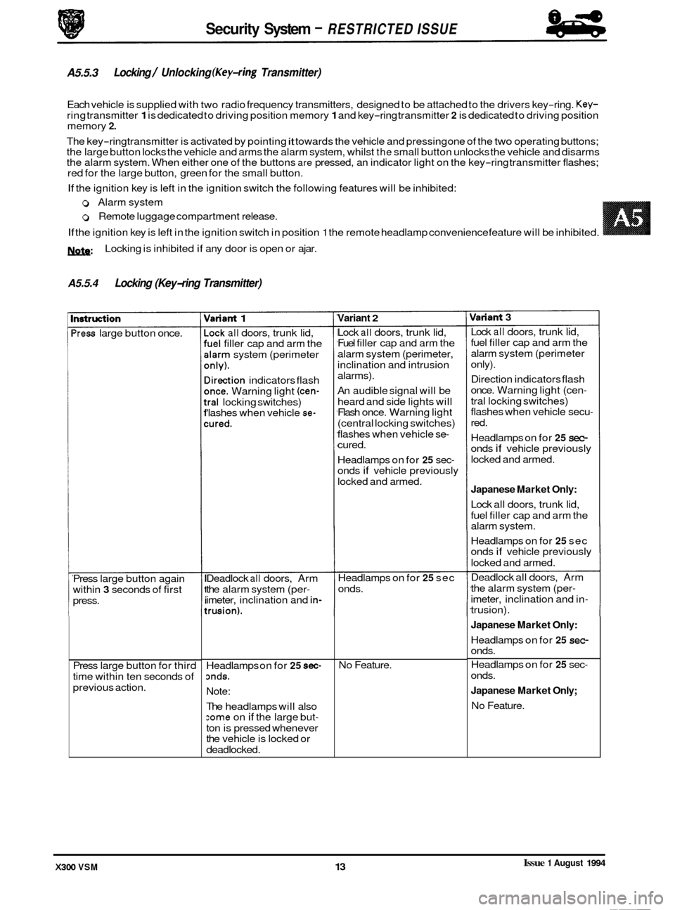
A5.5.4 Locking (Key-ring Transmitter)
Locking is inhibited if any door is open or ajar.
nstruction
'ress large button once.
Press large button again
within
3 seconds of first
press.
Press large button for third
time within ten seconds of
previous action.
rlariant 1
-ock all doors, trunk lid, 'uel filler cap and arm the
darm system (perimeter
mly).
lirection indicators flash
mce. Warning light (cen-
:ral locking switches)
'lashes when vehicle se-
:ured.
Deadlock all doors, Arm
the alarm system (per
- imeter, inclination and in-
:rusion).
Variant 2
Security System - RESTRICTED ISSUE
A5.5.3
Each vehicle is supplied with two radio frequency transmitters, designed to be attached to the drivers key-ring. Key- ring transmitter 1 is dedicated to driving position memory 1 and key-ring transmitter 2 is dedicated to driving position
memory 2.
The key-ring transmitter is activated by pointing it towards the vehicle and pressing one of the two operating buttons;
the large button locks the vehicle and arms the alarm system, whilst the small button unlocks the vehicle and disarms
the alarm system. When either one of the buttons are pressed, an indicator light on the key-ring transmitter flashes;
red for the large button, green for the small button.
If the ignition key is left in the ignition switch the following features will be inhibited:
Locking / Unlocking (Key-ring Transmitter)
0 Alarm system
0 Remote luggage compartment release.
If the ignition key is left in the ignition switch in position 1 the remote headlamp convenience feature will be inhibited. ~~ ~
Headlamps on for 25 sec- mds.
Note:
The headlamps will also :ome on if the large but-
ton is pressed whenever
the vehicle is locked or
deadlocked. Lock
all doors,
trunk lid,
Fuel filler cap and arm the
alarm system (perimeter,
inclination and intrusion
alarms).
An audible signal will be
heard and side lights will
Flash once. Warning light
(central locking switches)
flashes when vehicle se
- cured.
Headlamps on for
25 sec- onds if vehicle previously
locked and armed.
Headlamps on for
25 sec
onds.
No Feature.
Variant 3
Lock all doors, trunk lid,
fuel filler cap and arm the
alarm system (perimeter
only).
Direction indicators flash
once. Warning light (cen
-
tral locking switches)
flashes when vehicle secu-
red.
Headlamps on for
25 sec- onds if vehicle previously
locked and armed.
Japanese Market Only:
Lock all doors, trunk lid,
fuel filler cap and arm the
alarm system.
Headlamps on for
25 sec
onds if vehicle previously
locked and armed.
Deadlock all doors, Arm
the alarm system (per
-
imeter, inclination and in- trusion).
Japanese Market Only:
Headlamps on for 25 sec- onds.
Headlamps on for
25 sec-
onds.
Japanese Market Only;
No Feature.
Issue 1 August 1994 X300 VSM 13