wheel JAGUAR XJ6 1994 2.G Owner's Manual
[x] Cancel search | Manufacturer: JAGUAR, Model Year: 1994, Model line: XJ6, Model: JAGUAR XJ6 1994 2.GPages: 521, PDF Size: 17.35 MB
Page 132 of 521

Manual Transmission & Clutch (AJ16)
. Check the flywheel face for scoring; should this be excess-
Fit a new spigot bearing to the flywheel (2 Fig. 1).
. Refit the flywheel to the crankshaft and tighten the secur-
. Fit the clutch assembly to the flywheel ensuring that the
. Align the clutch with an input shaft.
. Fit the balance weights to the clutch cover and tighten the
. Remove the input shaft.
ive,
skim within tolerance.
ing bolts (1
Fig. 1).
larger, rounded boss faces the flywheel.
securing bolts. Remove the circlip
(1 Fig. 2) securing the clutch release
arm to the pivot and remove the assembly (2 Fig. 2).
. Slacken and remove the release arm pivot pin.
. Remove the bearing (3 Fig. 2) from the release arm assem- bly (2 Fig. 21, grease the bearing seat, fit the new bearing
to the release arm assembly.
Re-assemble the release arm ensuring that the pivots are
greased.
. Select third forward gear.
. Move the transmission under the ramp and raise it into
position against the adaptor plate and secure with the
bolts.
. Remove the securing chain from the unit lift and fit front
clamp.
. Refit the transmission switch and fit the multi-plug into
the securing clip.
. Refit the clutch slave cylinder, see 33.35 01.
. Fit the mounting rubbers and spacers, reconnect the re-
. Refit the selector to the gearshift lever.
. Refit the exhaust front pipes to the manifold.
. Remove the blanking plug from the rear of the trans-
. Refit the drive (propeller) shaft.
. Refit the heat shield and reconnect the exhaust system.
. Lower the ramp.
. Remove the Service Tool MS 53B.
. Remove the engine lifting eye 18G 1465.
= Refit the injector harness mounting bracket and tighten
the rear inlet manifold securing nuts.
mote control.
mission.
Fig. 2
Issue 1 August 1994 X300 VSM 15
-~
Page 140 of 521
Automatic Transmission (AJ16)
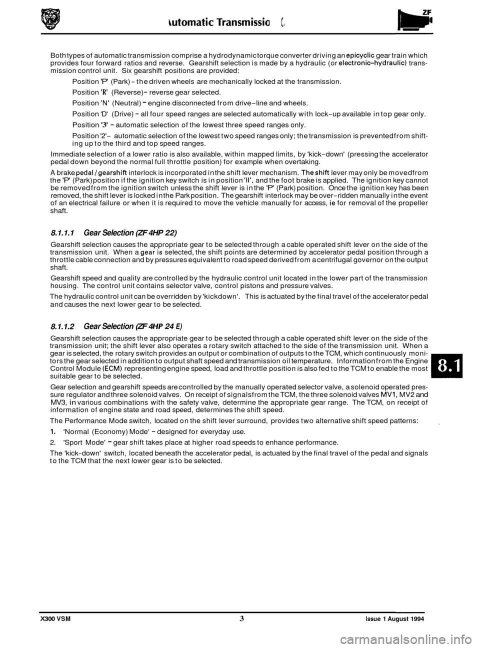
Both types of automatic transmission comprise a hydrodynamic torque converter driving an epicyclic gear train which
provides four forward ratios and reverse. Gearshift selection is made by a hydraulic (or electronichydraulic) trans- mission control unit. Six gearshift positions are provided:
Position
'P' (Park) -the driven wheels are mechanically locked at the transmission.
Position
'R' (Reverse) - reverse gear selected.
Position
'N' (Neutral) - engine disconnected from drive-line and wheels.
Position 'D' (Drive)
- all four speed ranges are selected automatically with lock-up available in top gear only.
Position
'3' - automatic selection of the lowest three speed ranges only.
Position '2'
- automatic selection of the lowest two speed ranges only; the transmission is prevented from shift- ing up to the third and top speed ranges.
Immediate selection of a lower ratio is also available, within mapped limits, by 'kick
-down' (pressing the accelerator
pedal down beyond the normal full throttle position) for example when overtaking.
A brake pedal/gearshift interlock is incorporated in the shift lever mechanism. Theshift lever may only be movedfrom
the 'P' (Park) position if the ignition key switch is in position 'll', and the foot brake is applied. The ignition key cannot
be removed from the ignition switch unless the shift lever is in the 'P' (Park) position. Once the ignition key has been
removed, the shift lever is locked in the Park position. The gearshift interlock may be over-ridden manually in the event
of an electrical failure or when it is required to move the vehicle manually for access, ie for removal of the propeller
shaft.
8.1.1.1
Gearshift selection causes the appropriate gear to be selected through a cable operated shift lever on the side of the
Gear Selection (ZF 4HP 22)
transmission unit. When a gea; is selected, the shift points are determined by accelerator pedal position through a
throttle cable connection and by pressures equivalent to road speed derived from a centrifugal governor on the output
shaft.
Gearshift speed and quality are controlled by the hydraulic control unit located in the lower part of the transmission
housing. The control unit contains selector valve, control pistons and pressure valves.
The hydraulic control unit can be overridden by 'kickdown'. This is actuated by the final travel of the accelerator pedal
and causes the next lower gear to be selected.
8.1.1.2
Gearshift selection causes the appropriate gear to be selected through a cable operated shift lever on the side of the
transmission unit; the shift lever also operates a rotary switch attached to the side of the transmission unit. When a
gear is selected, the rotary switch provides an output or combination of outputs to the TCM, which continuously moni
- tors the gear selected in addition to output shaft speed and transmission oil temperature. Information from the Engine
Control Module (ECM) representing engine speed, load and throttle position is also fed to the TCM to enable the most
suitable gear to be selected.
Gear selection and gearshift speeds are controlled by the manually operated selector valve, a solenoid operated pres
- sure regulator and three solenoid valves. On receipt of signalsfrom the TCM, the three solenoid valves MVI, MV2 and
MV3, in various combinations with the safety valve, determine the appropriate gear range. The TCM, on receipt of
information of engine state and road speed, determines the shift speed.
The Performance Mode switch, located on the shift lever surround, provides two alternative shift speed patterns:
1. 'Normal (Economy) Mode' - designed for everyday use.
2. 'Sport Mode'
- gear shift takes place at higher road speeds to enhance performance.
The 'kick
-down' switch, located beneath the accelerator pedal, is actuated by the final travel of the pedal and signals
to the TCM that the next lower gear is to be selected.
Gear Selection (ZF 4 HP 24 E)
X300 VSM 3 Issue 1 August 1994
Page 158 of 521

Powertrain Automatic Transmission (V12 & AJ16 Supercharged)
Light throttle D1 -D2 D2 - D3 D3 - D4
Normal mile 1 h 8- 10 18-20 25 - 39
kmlh 13- 15 28 - 33 40 - 46
sport mile 1 h 10 - 12 20 - 23 30 - 34
kmlh 16- 19 32 - 37 48-55
Up to Detent D1- D2 D2 - D3
Normal mile I h 34 - 37 60-66
kmlh 54 - 59 97 - 107
8.2.1.2 Shift Speeds
0
D4 - TCC on
45 - 51
72
-83
47
- 55
76
-88
D3
- D4
86
-94
138
- 151
4,O Liter Supercharged
sport mile I h 43 - 47 74 - 81 103 - 113
kmlh 69 - 76
118- 130
166 - 182
Maximum shift speeds (through detent)
Normal 1 Sport mile I h
kmlh
D1 -D2 D2 - D3 D3 - TCC on
47 - 50 81 -84
116 - 128
75
- 80 130 - 134
187 - 205
TCC
-Torque converter clutch
m: Road speeds shown above are for a vehicle with an axle ratio of 3,58:1, and standard tyres (2251 65ZR15). For
a vehicle with optional sports tyres
(225 / 55ZR16) (lattice wheels), these speeds must be reduced by 2,4%.
Zero throttle 1 TCCoffinD4 1 D4 - D3 D3 - D2
X300 VSM 3 Issue 1 August 1994
D2 - D1
Normal mile 1 h
kmth
sport mile 1 h
kmlh
I 36 - 40 15- 17
10- 12 -
58-64 24 - 27 16- 19 -
36 - 40 18 - 20 12 - 14
9-9
58-64 29 - 32 20 - 22 14 - 15
Up to
detent D4 - D3 03 - D2
Normal mile 1 h 67-74 3-44
kmlh 107-118 63-70
sport mile 1 h 81 -89 57 - 63
kmlh 130- 144 92 - 101
Kick-down available (through detent) TCC4 - D3 D3 - 02
Normal 1 Sport mile I h 103- 113 67 -74
kmlh 165 - 183 107 - 118 D2
- D1
9-9
14
- 15
27
- 29
43 - 47
D2
- D1
36 - 40
58-64
Page 159 of 521

Automatic Transmission (V12 & AJ16 Supercharged)
Light throttle D1 -D2
Normal mile 1 h -
km/h -
sport mile / h 10- 12
kmlh 16- 18
Up to detent
Normal mile I h
kmlh
sport mile
1 h
km/h
Maximum shift speeds (through detent)
Normal I Sport mile / h
kmlh
6,O Liier
D2 - D3
D3 - D4
D4 - TCC on
20 - 23 29 - 33
48 - 55
32
- 37 46 - 52
77 -88
23 - 26 32 - 37 51 -59
36
- 41 51 -59 82 - 94
D1 -D2
D2 - D3 D3 - D4
35
- 40 61 -70 83-91
56
- 64 98- 112 133 - 164
43 - 49 73 - 79 99 -107
68
-78 117 - 127 158 - 172
D1 -D2 D2 - D3
D3 - TCC on
48-53 81 -89
116- 124
77
- 85 130- 149
186 - 198
Zero throttle
Normal mile 1 h
kmlh
sport mile
1 h
km/h
TCC off in 04 D4 - D3 D3 - D2 D2 - D1
- 36 - 40 15 - 17 10 - 12
16
- 19 58 - 64 24 - 27
36
- 40 18 - 20 12-14 6-7
58
- 64 29 - 32 19 - 22 10- 12
-
0
0
Up to detent
Normal mile I h
kmlh
sport mile
/ h
km/h
mile I h
kmlh
'Kick-down' available (through detent)
Normal 1 Sport
TCC -Torque converter clutch
m: Road speeds shown above are for a vehicle with an axle ratio of 3,58:1, and standard tyres (2251 65ZR15). For
a vehicle with optional sports tyres
(225 155ZR16) (lattice wheels), these speeds must be reduced by 2,4%.
D4 - D3 D3 - D2 D2 - D1
67 - 75 37 - 41 7-9
108
- 119 59 - 66 11 - 14
84
-92 60 - 66
27 - 29
134
- 148 96 - 106
43 - 47
TCC4
- D3 03 - D2 D2 - D1
103 - 113 67 -75 36 - 40
164
- 181 108 - 119 58 - 64
0
0
Issue 1 August 1994 4 X300 VSM
Page 183 of 521
-5 Driveshafts & Final Drive
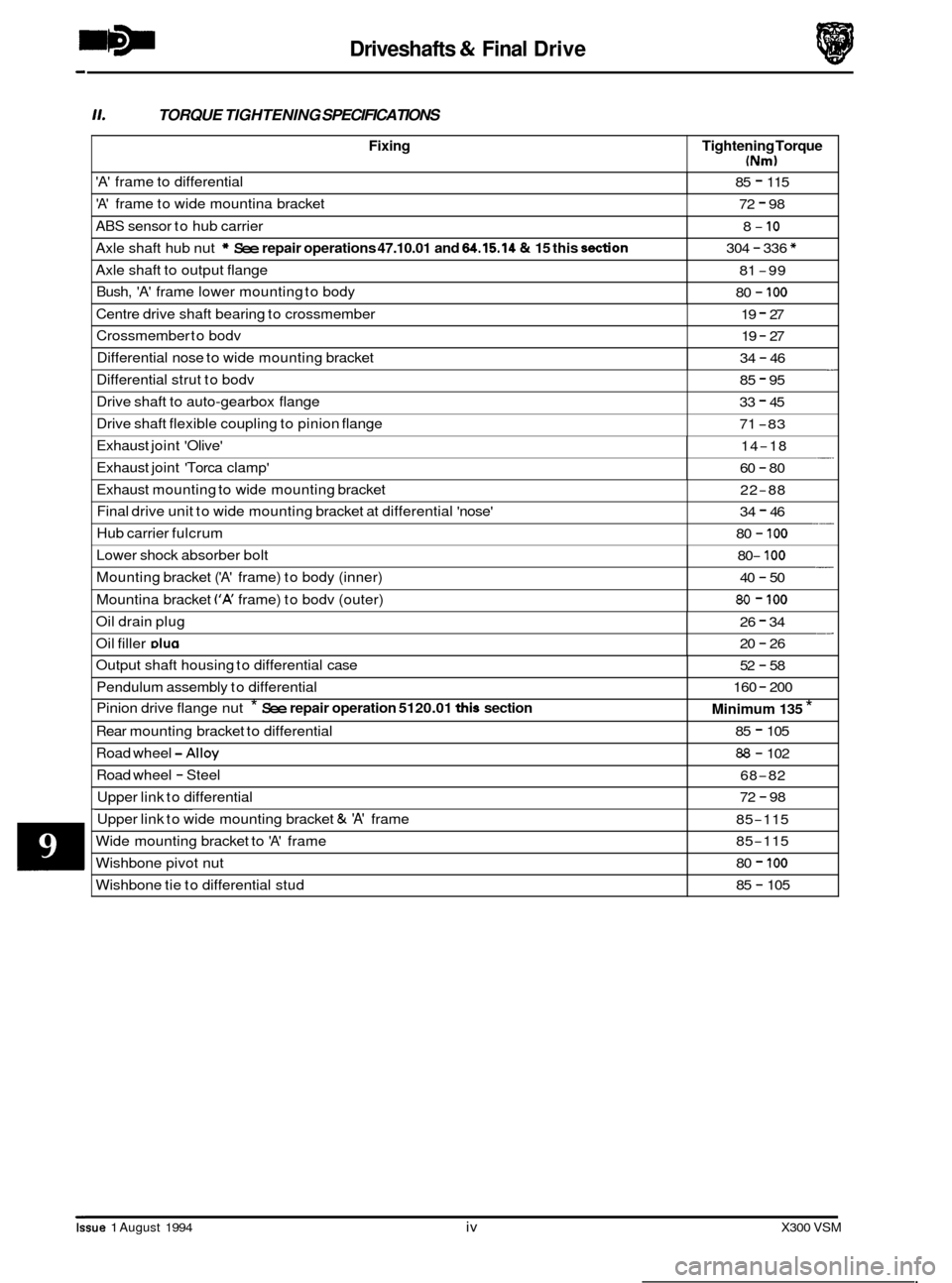
0
Fixing
11. TORQUE TIGHTENING SPECIFICATIONS
Tightening Torque
(Nm)
'A' frame to differential 85 - 115
'A' frame to wide mountina bracket 72 - 98
ABS sensor to hub carrier
Axle shaft hub nut
* See repair operations 47.10.01 and 64.15.14 & 15 this don
8- 10
304 - 336 *
Axle shaft to output flange
Bush,
'A' frame lower mounting to body
81 -99
80
- 100
Centre drive shaft bearing to crossmember 19 - 27
Crossmember to bodv 19 - 27
Differential nose to wide mounting bracket - 34 - 46
Issue 1 August 1994 iv X300 VSM
Differential strut to bodv 85 - 95
Drive shaft to auto-gearbox flange
Drive shaft flexible coupling to pinion flange 33 - 45
71
-83
Exhaust joint 'Olive'
Exhaust joint 'Torca clamp' -. 14-18
60
- 80
Exhaust mounting to wide mounting bracket
Final drive unit to wide mounting bracket at differential 'nose'
Hub carrier fulcrum 22-88
34
- 46
80
- 100 ___
Lower shock absorber bolt
Mounting bracket
('A' frame) to body (inner)
Mountina bracket
('A' frame) to bodv (outer)
- 80- 100
40 - 50
80 - 100
Oil drain plug __ 26 - 34
Oil filler DIU~ 20 - 26
Output shaft housing to differential case
Pendulum assembly to differential
Pinion drive flange nut
* See repair operation 5120.01 this section
Road wheel -Alloy
Road wheel - Steel
Upper link to differential
Rear
mounting bracket to differential
52 - 58
160
- 200
Minimum 135 *
85 - 105
88 - 102
68
-82
72
- 98 ~~~~~
Upper
link to wide mounting bracket & 'A' frame
Wide mounting bracket to
'A' frame
85-115
85
-115
Wishbone pivot nut
Wishbone tie to differential stud 80 - 100
85 - 105
Page 186 of 521
Driveshafts & Final Drive
9.1 MAJOR COMPONENT DESCRIPTION
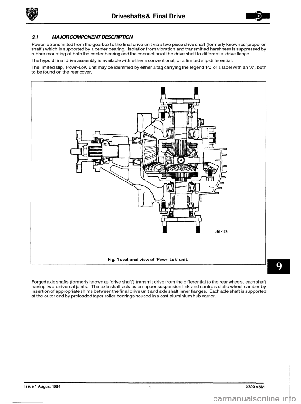
Power is transmitted from the gearbox to the final drive unit via a two piece drive shaft (formerly known as ‘propeller
shaft’) which is supported by a center bearing. Isolation from vibration and transmitted harshness is suppressed by
rubber mounting of both the center bearing and the connection of the drive shaft to differential drive flange.
The
hypoid final drive assembly is available with either a conventional, or a limited slip differential.
The limited slip, ‘Powr
-LoK unit may be identified by either a tag carrying the legend ’PC or a label with an ‘X, both
to be found on the rear cover.
U
Forged axle shafts (formerly known as ‘drive shaft’) transmit drive from the differential to the rear wheels, each shaft
having two universal joints. The axle shaft acts as an upper suspension link and controls static wheel camber by insertion of appropriate shims between the final drive unit and axle shaft inner flanges. Each axle shaft is supported
at the outer end by preloaded taper roller bearings housed in a cast aluminium hub carrier.
Page 189 of 521
Driveshafts & Final Drive
9.3
SRO 51.10.24
Disconnect vehicle battery ground lead.
. Support the vehicle at the rear.
OUTPUT SHAFT END FLOAT, CHECK
Mount a dial test indicator (DTI) to the differential housing with the probe resting on the output shaft flange (DTI probe must be parallel to the output shaft center line and NOT at an angle).
. Push the wheel 1 shaft assembly inwards and zero the DTI; pull outwards and note the reading.
. If the end float exceeds 0,15 mm; firstly verify the shim preload and if this is found to be correct, renew the output
shaft bearing. See 51.10.22. this section, for shim check and renew operations.
9.4
SRO 51.20.19
rn Disconnect vehicle battery ground lead.
See operation 51.10.22. this section, for process detail, less bearing 1 oil seal renew.
OUTPUT SHAFT HOUSING ‘0’ RING, RENEW
Prior to removal of shaft assembly check output shaft end float in accordance with operation 51.10.24.
9.5 OIL SEAL - PINION FLANGE, RENEW
SRO 51.20.01
. Disconnect vehicle battery ground lead.
. Support the vehicle at the rear.
. Disconnect main handbrake cable at compensator.
’Match mark‘ the FLEXIBLE COUPLING to the differential DRIVE FLANGE and remove fixings.
Remove fixings center bearing to crossmember and push drive shaft rear section forward to disengage from pinion
spigot.
CAUTION: Under no circumstances must the flexible coupling (or its fixings) be loosened or removed from the drive
shaft flange.
Support the drive shaft, do not allow it to hang.
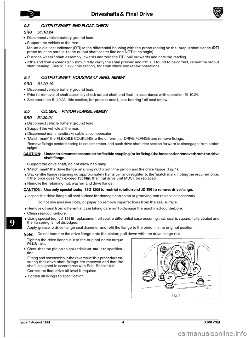
9 ‘Match mark‘ the drive flange retaining nut to both the pinion and the drive flange (Fig. 1).
. Slacken the flange retaining nut approximately half a turn and retighten to the ‘match mark‘ noting the required force.
. Remove the retaining nut, washer and drive flange.
CAUTION: Use only special tools; 18G 1205 to restrict rotation and JD 156 to remove drive flange.
. Inspect the drive flange oil seal surface for damage corrosion or grooving and replace as necessary.
. Remove oil seal from differential case taking care not to damage the machined counterbore.
rn Clean seal counterbore.
. Using special tool JD 198 fit replacement oil seal to differential case ensuring that, seal is square, fully seated and
If the force does NOT exceed 135 Nm, the final drive unit MUST be replaced.
Do not use abrasive cloth, or paper, to remove imperfections from the seal surface.
the
lip spring is not dislodged.
Apply grease to drive flange seal diameter and refit the flange to the pinion in the original position.
U: Do not hammer the drive flange onto the pinion; pull down with the drive flange nut.
Tighten the drive flange nut to the original noted torque PLUS 10%.
* Check that the pinion spigot radial run-out is to specifica- tion.
Fitting and reassembly is the reversal of this procedure en
- suring that drive shaft fixings are renewed and that the
shaft is aligned in accordance with Sub-Section 9.2.
Correct the final drive oil level if required.
. Tighten all fixings to specification.
Fig. 1
0
Issue 1 August 1994 4 X300 VSM
Page 190 of 521
Driveshafts & Final Drive
9.6 OUTPUT SHAFT BEARING, RENEW
@ SRO 51.10.22
9.7
SRO 51.20.04
. Disconnect vehicle battery ground lead.
. Support the vehicle at the rear and remove the rear road wheel (or wheels).
9 'Match mark' the axle shaft flange to the output shaft flange and remove fixings, note camber shim.
. Thoroughly clean the area around the output shaft housing and differential case.
. Release fixings and remove output shaft assembly, discard '0' ring.
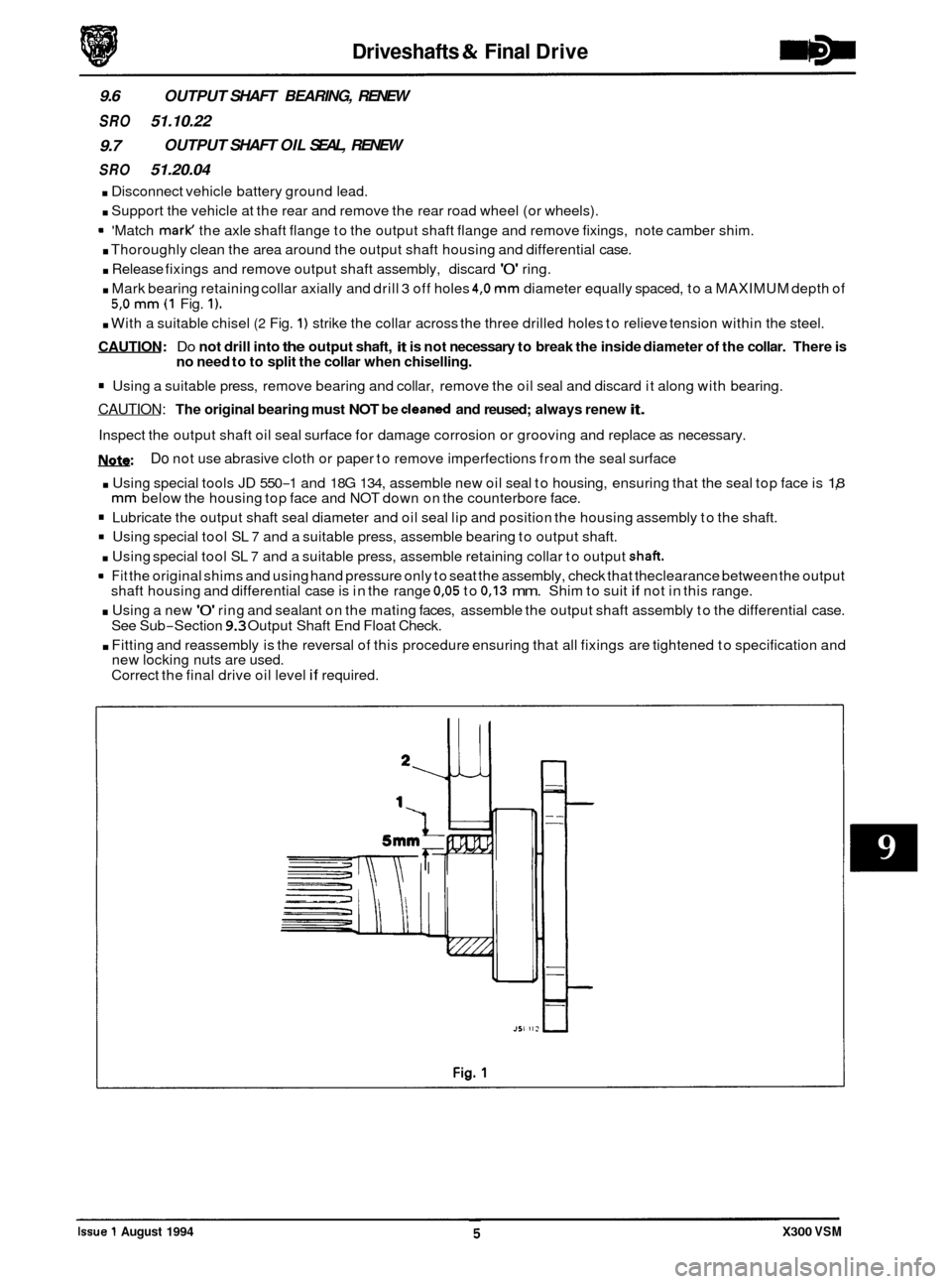
. Mark bearing retaining collar axially and drill 3 off holes 4,O mm diameter equally spaced, to a MAXIMUM depth of
. With a suitable chisel (2 Fig. 1) strike the collar across the three drilled holes to relieve tension within the steel.
CAUTION: Do not drill into the output shaft, it is not necessary to break the inside diameter of the collar. There is
no need to to split the collar when chiselling.
Using a suitable press, remove bearing and collar, remove the oil seal and discard it along with bearing.
CAUTION: The original bearing must NOT be cleaned and reused; always renew it.
Inspect the output shaft oil seal surface for damage corrosion or grooving and replace as necessary.
W:
OUTPUT SHAFT OIL SEAL, RENEW
5,O mm (1 Fig. 1).
Do not use abrasive cloth or paper to remove imperfections from the seal surface
. Using special tools JD 550-1 and 18G 134, assemble new oil seal to housing, ensuring that the seal top face is 1,8 mm below the housing top face and NOT down on the counterbore face.
Lubricate the output shaft seal diameter and oil seal lip and position the housing assembly to the shaft.
Using special tool SL 7 and a suitable press, assemble bearing to output shaft.
. Using special tool SL 7 and a suitable press, assemble retaining collar to output shaft.
= Fit the original shims and using hand pressure only to seat the assembly, check that theclearance between the output
. Using a new '0' ring and sealant on the mating faces, assemble the output shaft assembly to the differential case.
. Fitting and reassembly is the reversal of this procedure ensuring that all fixings are tightened to specification and
shaft
housing and differential case is in the range
0,05 to 0,13 mm. Shim to suit if not in this range.
See Sub
-Section 9.3 Output Shaft End Float Check.
new locking nuts are used.
Correct the final drive oil level
if required.
Issue 1 August 1994 X300 VSM
Page 191 of 521
Driveshafts & Final Drive
9.8 FINAL DRWE UNIT RENEW
SRO 51.25.13
. Disconnect vehicle battery ground lead.
. Support the vehicle at the rear and remove the rear road
wheels.
Disconnect brake pad wear sensor multi-plug at RH hub
carrier and remove tie straps from wishbone. Release
ABS speed sensors at
RH and LH hub carriers and remove
tie straps from wishbones.
. Remove rear brake calipers, see Section 12, and support
at bump stop. Disconnect main handbrake cable at com- pensator, short cables at joining piece and remove com- pensator.
. Remove fixings, FLEXIBLE coupling to differential DRIVE FLANGE.
CAUTIW: Under no circumstances must the flexible
coupling (or itsfixings) be loosened or removed
from the drive shaft flange.
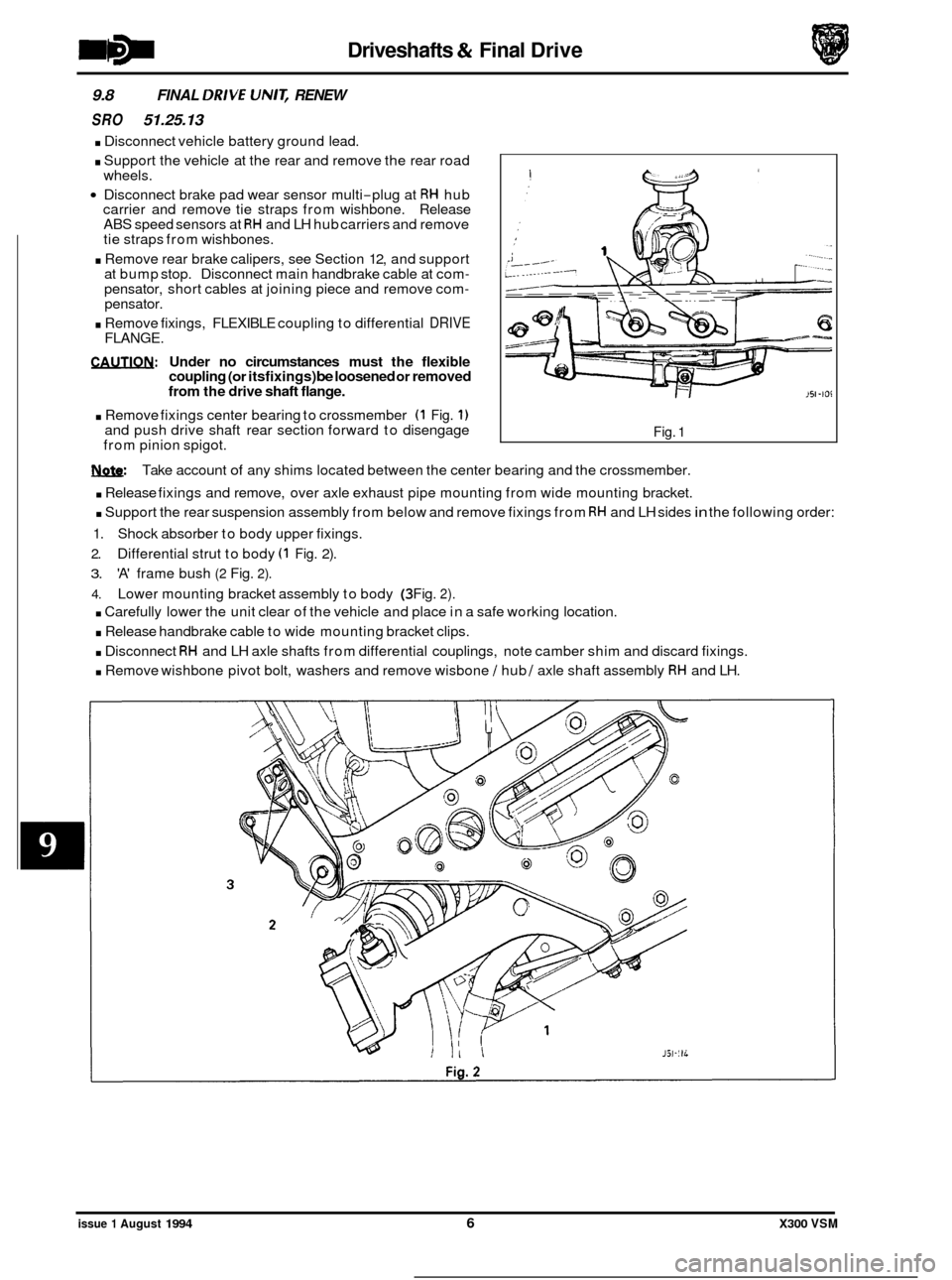
. Remove fixings center bearing to crossmember (1 Fig. 1) and push drive shaft rear section forward to disengage
from pinion spigot. Fig. 1
w: Take account of any shims located between the center bearing and the crossmember.
. Release fixings and remove, over axle exhaust pipe mounting from wide mounting bracket.
. Support the rear suspension assembly from below and remove fixings from RH and LH sides in the following order:
1. Shock absorber to body upper fixings.
2. Differential strut to body (1 Fig. 2).
3. 'A' frame bush (2 Fig. 2).
4. Lower mounting bracket assembly to body (3 Fig. 2).
. Carefully lower the unit clear of the vehicle and place in a safe working location.
. Release handbrake cable to wide mounting bracket clips.
. Disconnect RH and LH axle shafts from differential couplings, note camber shim and discard fixings.
. Remove wishbone pivot bolt, washers and remove wisbone / hub / axle shaft assembly RH and LH.
issue 1 August 1994 6 X300 VSM
Page 192 of 521
Driveshafts & Final Drive
. Remove upper link assembly from differential and wide mounting bracket / 'A' frame.
. Release fixings, 'A' frame to differential, 'A' frame to wishbone tie and wide mounting bracket to 'A' frame.
. Remove wishbone tie assembly, rear mounting bracket and pendulum assembly.
. Release fixings differential nose to wide mounting bracket.
. Assembly and fitting is the reversal of this procedure, taking note of the following:
Drive shaft must be aligned in accordance with Sub
-Section 9.2.
Renew all self locking nuts.
Renew all bolts that were originally fitted with thread locking adhesive.
Replace all locking wire and split pins (cotter pins).
Tighten all fixings to the specified torque.
Correct the final drive oil level
if required.
Check and adjust rear wheel camber setting as required.
9.9 AXLE SHAFT ASSEMBLY, RENEW
SRO
47.10.01
Disconnect vehicle battery ground lead.
. Slacken appropriate axle shaft hub nut.
. Support the vehicle at the rear and remove rear road
. Remove brake caliper in accordance with 70.55.03. Sec-
wheel.
tion 12, but do not disconnect hydraulics.
Slacken hub carrier fulcrum and remove ABS sensor from
hub carrier.
. Remove axle shaft hub nut and collar.
. Remove fixings axle shaft to differential output shaft
flange, note camber shim.
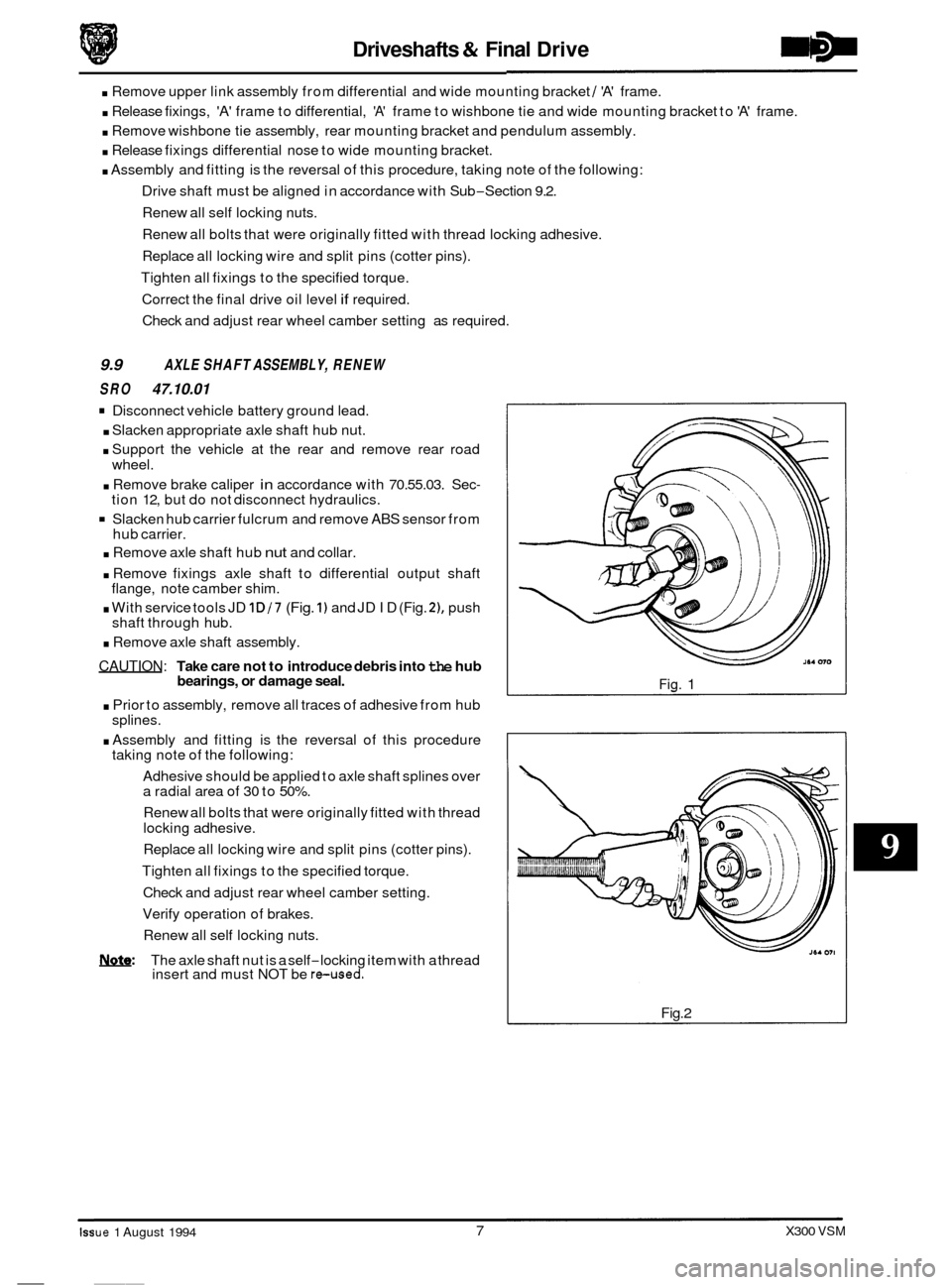
. With service tools JD 1D/7 (Fig. 1) and JD ID (Fig. 21, push
shaft through hub.
. Remove axle shaft assembly.
CAUTION: Take care not to introduce debris into the hub
bearings, or damage seal.
. Prior to assembly, remove all traces of adhesive from hub
. Assembly and fitting is the reversal of this procedure
Adhesive should be applied to axle shaft splines over
a radial area of
30 to 50%.
Renew all bolts that were originally fitted with thread
locking adhesive.
Replace all locking wire and split pins (cotter pins).
Tighten all fixings to the specified torque.
Check and adjust rear wheel camber setting.
Verify operation of brakes.
Renew all self locking nuts.
splines.
taking
note of the following:
0
NQ&: The axle shaft nut is a self-locking item with a thread
insert and must NOT be reused.
Fig. 1
Fig.2
- Iss ue 1 August 1994
__~
7 X300 VSM