ignition JAGUAR XJ6 1994 2.G Service Manual
[x] Cancel search | Manufacturer: JAGUAR, Model Year: 1994, Model line: XJ6, Model: JAGUAR XJ6 1994 2.GPages: 521, PDF Size: 17.35 MB
Page 357 of 521
15.6
15.6.1
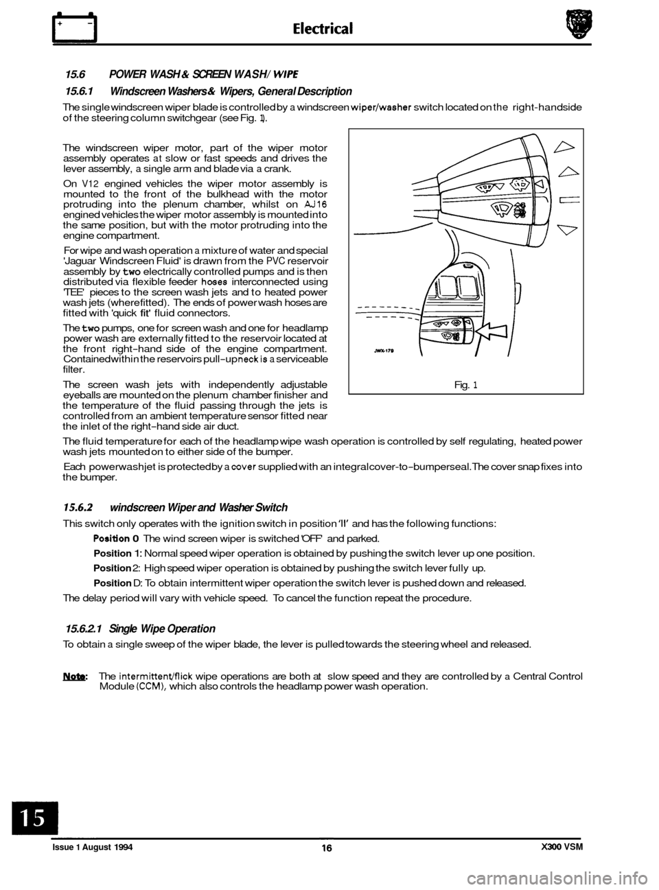
The single windscreen wiper blade is controlled by a windscreen wiper/washer switch located on the right-hand side
of the steering column switchgear (see Fig.
1).
POWER WASH & SCREEN WASH/ WlPE
Windscreen Washers & Wipers, General Description
The windscreen wiper motor, part of the wiper motor
assembly operates at slow or fast speeds and drives the
lever assembly, a single arm and blade via a crank.
On
V12 engined vehicles the wiper motor assembly is
mounted to the front of the bulkhead with the motor
protruding into the plenum chamber, whilst on AJ16 engined vehicles the wiper motor assembly is mounted into
the same position, but with the motor protruding into the
engine compartment.
For wipe and wash operation
a mixture of water and special
'Jaguar Windscreen Fluid' is drawn from the PVC reservoir
assembly by
two electrically controlled pumps and is then
distributed via flexible feeder hoses interconnected using
'TEE' pieces to the screen wash jets and to heated power
wash jets (where fitted). The ends of power wash hoses are
fitted with 'quick
fit' fluid connectors.
The
two pumps, one for screen wash and one for headlamp
power wash are externally fitted to the reservoir located at
the front right
-hand side of the engine compartment.
Contained within the reservoirs pull-up neckis a serviceable
filter.
The screen wash jets with independently adjustable
eyeballs are mounted on the plenum chamber finisher and
the temperature of the fluid passing through the jets is
controlled from an ambient temperature sensor fitted near
the inlet of the right
-hand side air duct. Fig.
1
The
fluid temperature for each of the headlamp wipe wash operation is controlled by self regulating, heated power
wash jets mounted on to either side of the bumper.
Each powerwash jet is protected by
a cover supplied with an integral cover-to-bumperseal. The cover snap fixes into
the bumper.
15.6.2
This switch only operates with the ignition switch in position '11' and has the following functions:
windscreen Wiper and Washer Switch
Position 0 The wind screen wiper is switched 'OFF' and parked.
Position 1: Normal speed wiper operation is obtained by pushing the switch lever up one position.
Position 2: High speed wiper operation is obtained by pushing the switch lever fully up.
Position D: To obtain intermittent wiper operation the switch lever is pushed down and released.
The delay period will vary with vehicle speed. To cancel the function repeat the procedure.
15.6.2.1 Single Wipe Operation
To obtain a single sweep of the wiper blade, the lever is pulled towards the steering wheel and released.
W The intermittenmick wipe operations are both at slow speed and they are controlled by a Central Control
Module (CCM), which also controls the headlamp power wash operation.
Issue 1 August 1994 X300 VSM
Page 358 of 521
15.6.2.2 Programmed Wash / Wipe Operation
The end of the switch lever must be pressed inwards for the windscreen wash and wipe operation. Wash / wipe con- tinues for as long as the lever is pressed.
When released, the windscreen wiper stops immediately and the wiper blades sweep for
a further three wipes.
On pressing the end of the switch lever inward and then releasing
it, the windscreen washers operate for approximately
two seconds before stopping, whilst the wiper blade continues for a further three wipes.
N&: If the end of the switch lever is pressed while the washer fluid warning light is illuminated, the windscreen
washers, but not the wiper blade continues to operate.
0
15.6.2.3 Headlamp Power Wash Operation (where fitfed)
The headlamp power wash operates only when the programmed washer/ wipe function is selected and the side lights
are 'ON'
The headlamp power wash does not operate if the windscreen washer reservoir fluid lever is low. This is indicated
by the washer fluid level warning light illuminating.
&&: The headlamp power wash only operates on the 1st and every 6th succeeding cycle of the programme wash /wipe switch, after the ignition switch has been turned to position '11'.
X300 VSM 17 Issue 1 August 1994
Page 374 of 521
Black
Black
Black All
models
All Models
All Models
Black
Black All
Models
All Models
Black/
White Stripe
Black/
White Stripe
Black Non
Aircon.
Models
only
Non Power
Wash Models
only
Optional
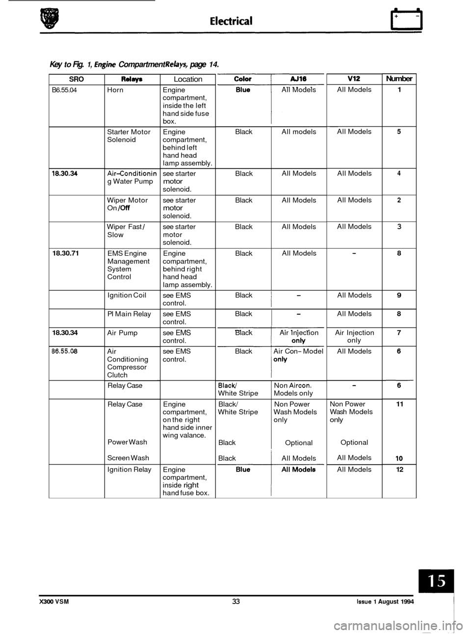
0 Key to Fig. 1, hgine Compartment Relays, page 14.
Number v12 Color
All Models
SRO
B6.55.04
Rdaw
Horn
Location
Engine
compartment,
inside the left
hand side fuse box.
Engine
compartment,
behind left hand head
lamp assembly.
see starter
motor
solenoid. All
Models
1 ~~
All
Models 5 Starter Motor
Solenoid
4 All Models
All Models 18.30.34 Air-conditionin
g Water Pump
Wiper Motor
On
/Off
2 see starter
motor
solenoid.
see starter
motor
solenoid. All
Models
3 Wiper Fast /
Slow
18.30.71 Engine
compartment, behind right
hand head
lamp assembly. 8 EMS Engine
Management
System
Control
Black
I
All Models 9 Ignition Coil
PI Main Relay see
EMS
control.
see EMS
control. Black
I
All
Models 8
Air Pump 7 see EMS
control.
see EMS
control. Black
Air Injection
Black Air Con
- Model Air
Injection
only
All Models
18.30.34
86.55.08 Air
Conditioning
Compressor
Clutch
Relay Case
Engine
compartment,
on the right
hand side inner
wing valance.
Relay
Case Non Power
Wash
Models
only
11
10
12
Power Wash
Screen Wash Optional
All Models
All Models
Black
All Models
Ignition Relay
Engine
compartment,
inside
right
hand fuse box.
X300 VSM 33 Issue 1 August 1994
Page 376 of 521
I SRO I Rdw* AJ16 v12
Automatic Automatic
Models only Models only
Automatic Automatic
Models only Models only
UK
& ROW -
Manual Seat
only
UK
& ROW -
Manual Seat
onh/
UK & ROW -
Manual Seat
only
Manual Seat
only
UK
& Manual -
Seat only
UK
& Manual -
Seat only
UK
& ROW -
Optional
Optional
Optional Optional
Keylock
Number
13
14
15
16
34
35
17
36
37
38
Driver's Seat Height
Control (Upward)
Driver's Seat Height
Control (Downward)
Passenger Seat
Height Control (Upward)
Passenger Seat
Height Control
(Downward)
Driver's Seat Heater
All Models
All Models
All Models
Passenger Seat
Heater
RH Front
Screen
Heater
LH Front Screen
Heater
Ignition All Models
25
All Models 26
All Models 23
Ignition
Air
-conditioning
Isolate
LH Blower
RH Blower
LH Blower
high
speed
RH Blower high
speed
Deadlock front
lefthear right All
Models All Models
20
Below gear selector 'J' gate.
Not NAS or
Japan
UK
& Europe
only
All Models
All Models
USA
&
Canada only
All Models
All Models
All Models
All Models
Below
gear selector
'J' gate.
Not NAS or
30
UK & Europe 31
All Models 28
All Models 29
USA & 27
All Models 24
All Models 33
All Models 22
All Models 32
Japan
only
Canada only
On
seat panel below
driver's seat.
86.55.78
86.55.74
On seat panel below
driver's seat.
Deadlock front
righthear left
Door Lock
Door Unlock
Driver's Door
Unlock
Mirror Heater
Puddle Lamps
Cigar Lighter
Fuel Flap Lock On
seat panel below
passenger's seat.
On seat panel below
passenger's seat.
On seat panel below
driver's seat.
On seat panel below
passenger's seat.
Left hand side footwell on
front
'A' post, behind cover.
Left hand side footwell on
front
'A' post, behind cover.
Fuse box assembly
RH side heelboard.
Fuse box assembly
LH side heelboard.
Behind
RH side heelboard.
Behind
RH side heelboard.
Behind RH side heelboard.
Behind
RH side heelboard.
Behind
RH side heelboard.
Behind LH side heelboard.
Behind LH side heelboard.
Behind LH side heelboard.
Behind LH side heelboard.
Behind LH side heelboard.
Behind
RH side heelboard.
Behind LH side heelboard.
Behind
RH side heelboard.
Behind LH side heelboard.
Color
Blue
Blue
Violet
Violet
Violet Violet Blue Blue
Blue
Blue
Blue
Blue
Blue
Blue
Blue Blue
Blue
Violet
Violet
Violet
Violet
Violet
Violet Blue
Blue
Violet All
Models All Models
All Models All Models
All Models All Models
18
X300 VSM 35 Issue 1 August 1994
Page 398 of 521

0
Engine Bay Fuse Box - right-hand side
Fuse No. Fuse Colour Code
- F1
F2 Red
F3
F4 Red
F5 Red
-
F6 Tan
F7 Clear
F8 Red
F9 -
FIO Tan
F12 Red
F13 Red
F14 Red F15
-
F16 Red
F17 Light Green
F18 Red
Value
(amps)
10
10
10
5
25
10
-
5
20
10
10
10
10
30
10
Circuit
Not used
Main beam headlamp
- right-hand side
Not used
Lowered beam
headlamD - riaht-hand side ."
Side light -front right-hand side
Turn indicator
-front right-hand side
Side repeater flasher
- right-hand side
Engine control module
(ECM)
Air pump (6 cyl. - where fitted)
Ignition coils
(VIZ)
Air conditioning clutch
Not used
Generator
Front lighting control module
- right-hand
Air conditioning clutch
Windshield wash
J headlamp power wash heaters and relays
Engine management system relay supply
Injectors
Engine management system
Starter relay Ignition coil sensing and air pump relay (6
cyl.)
Fuel injection relay
Engine management sensing
(VIZ)
Windshield washer pump
Lambda heaters
Idle speed control valve
Not used
Air pump control
Solenoid vacuum valve
(VIZ)
Water pump (supercharged)
Headlamp power wash pump
Front fog lamp
- right-hand side (where fitted)
0
0
Issue 1 August 1994 X300 VSM AI-95MY 15
Page 399 of 521
Specification
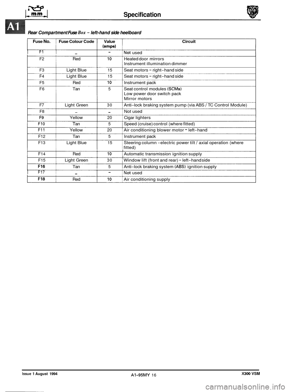
Rear Compartment Fuse Box - left-hand side heelboard
Fuse No. Fuse Colour Code Value Circuit
(amps)
I F1 I - I - lNot used
F2 Red 10 Heated door mirrors
F3 Light Blue 15 Seat motors - right-hand side
F4 Light Blue 15 Seat motors - right-hand side
F5 Red 10 Instrument pack
F6 Tan 5 Seat control modules (SCMs)
Low power door switch pack
Mirror motors
Instrument
illumination dimmer
F7 Light Green 30 Anti-lock braking system pump (via ABS / TC Control Module)
F8 - - Not used
F9 Yellow 20 Cigar lighters
FIO Tan 5 Speed (cruise) control (where fitted)
F11 Yellow 20 Air conditioning blower motor - left-hand
F12 Tan 5 Instrument pack
F13 Light Blue 15 Steering column -electric power tilt / axial operation (where
j fitted) 1 I I F14 Red 10 i Automatic transmission ignition supply I I I F15 Light Green 30 I Window lift (front and rear) - left-hand side
Tan
I 5 1 Anti-lock braking system (ABS) ignition supply
I F17 1 - I - lNot used
Red
I 10 I Air conditioning supply
Rear Compartment Fuse Box - left-hand side heelboard ~~
X300 VSM Issue 1 August 1994 AI-95MY 16
0
0
0
Page 406 of 521

Routine Maintenance
SERVICE SCHEDULE - UK, EUROPe ROW
3.2 Liter, 4.0 Liter, 4.0 Liter SC and 6.0 Liter
0
0
Note: This note only applies to VI2 engines.
When renewing spark plugs, apply silicon grease
(TBA) to the spark plug and coil terminals of the ignition
cable. This will ensure that the terminal covers remain supple throughout their service life, thus maintaining
a good contact and preventing HT leakage.
A2-95MY 3 Issue 1 August 1994 X300 VSM
Page 408 of 521
j
8
9
10
13 I
18
19
23
24
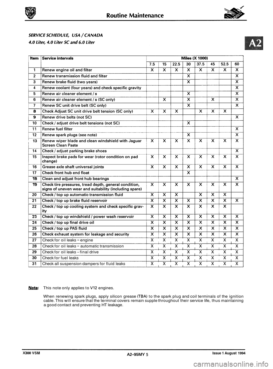
Check for oil leaks - engine xxxxxxxx
Check for oil leaks - automatic transmission xxxxxxxx
Check for oil leaks -final drive xxxxxxxx
Check for fuel leaks xxxxxxxx
Check all suspension dampers for fluid leaks xxxxxxxx
Note: This note only applies to VI2 engines.
When renewing spark plugs, apply silicon grease
CTBA) to the spark plug and coil terminals of the ignition
cable. This will ensure that the terminal covers remain supple throughout their service life, thus maintaining
a good contact and preventing HT leakage.
Issue 1 August 1994 A2-95MY 5 X300 VSM
Page 412 of 521
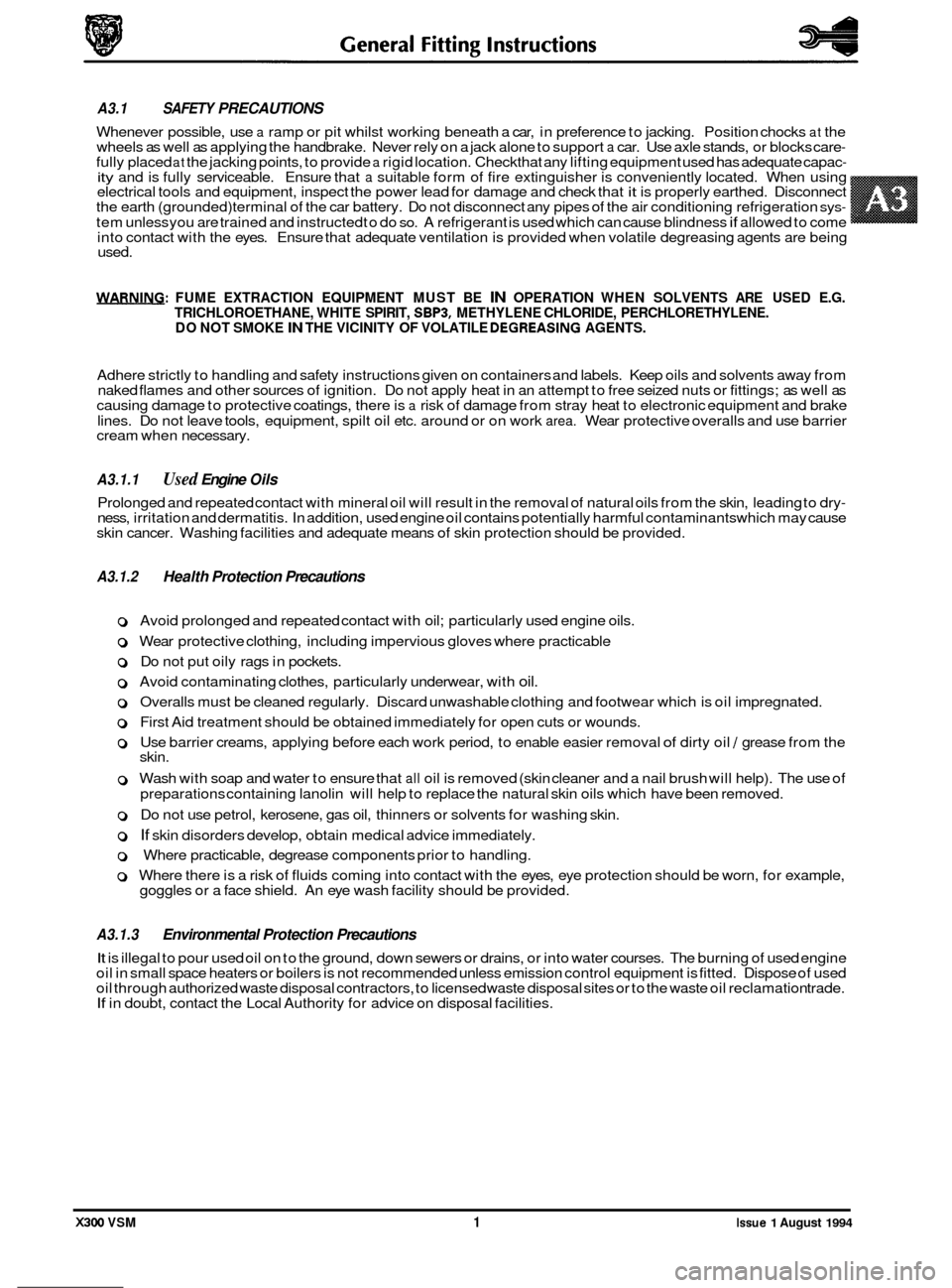
used.
WARNING: FUME EXTRACTION EQUIPMENT MUST BE IN OPERATION WHEN SOLVENTS ARE USED E.G.
TRICHLOROETHANE, WHITE SPIRIT, SBPB, METHYLENE CHLORIDE, PERCHLORETHYLENE.
DO NOT SMOKE IN THE VICINITY OF VOLATILE DEGREASING AGENTS.
Adhere strictly to handling and safety instructions given on containers and labels. Keep oils and solvents away from
naked flames and other sources of ignition. Do not apply heat in an attempt to free seized nuts or fittings; as well as
causing damage to protective coatings, there is
a risk of damage from stray heat to electronic equipment and brake
lines. Do not leave tools, equipment, spilt oil etc. around or on work
area. Wear protective overalls and use barrier
cream when necessary.
0 A3.1.1 Used Engine Oils
Prolonged and repeated contact with mineral oil will result in the removal of natural oils from the skin, leading to dry- ness, irritation and dermatitis. In addition, used engine oil contains potentially harmful contaminants which may cause
skin cancer. Washing facilities and adequate means of skin protection should be provided.
A3.1.2 Health Protection Precautions
0 Avoid prolonged and repeated contact with oil; particularly used engine oils.
o Wear protective clothing, including impervious gloves where practicable
0 Do not put oily rags in pockets.
0 Avoid contaminating clothes, particularly underwear, with oil.
0 Overalls must be cleaned regularly. Discard unwashable clothing and footwear which is oil impregnated.
o First Aid treatment should be obtained immediately for open cuts or wounds.
0 Use barrier creams, applying before each work period, to enable easier removal of dirty oil / grease from the
skin.
0 Wash with soap and water to ensure that all oil is removed (skin cleaner and a nail brush will help). The use of
preparations containing lanolin will help to replace the natural skin oils which have been removed.
o Do not use petrol, kerosene, gas oil, thinners or solvents for washing skin.
0 If skin disorders develop, obtain medical advice immediately.
0 Where practicable, degrease components prior to handling.
0 Where there is a risk of fluids coming into contact with the eyes, eye protection should be worn, for example,
goggles or a face shield. An eye wash facility should be provided.
A3.1.3 Environmental Protection Precautions
A3.1 SAFETY PRECAUTIONS
Whenever possible, use a ramp or pit whilst working beneath a car, in preference to jacking. Position chocks at the
wheels as well as applying the handbrake. Never rely on a jack alone to support a car. Use axle stands, or blocks care- fully placed at the jacking points, to provide a rigid location. Checkthat any lifting equipment used has adequate capac- ity and is fully serviceable. Ensure that a suitable form of fire extinguisher is conveniently located.
When using
electrical tools and equipment, inspect the power lead for damage and check that it is properly earthed. Disconnect
the earth (grounded) terminal of the car battery. Do not disconnect any pipes of the air conditioning refrigeration sys-
tem unless you are trained and instructed to do so. A refrigerant is used which can cause blindness if allowed to come
into contact with the eyes. Ensure that adequate ventilation is provided when volatile degreasing agents are being
It is illegal to pour used oil on to the ground, down sewers or drains, or into water courses. The burning of used engine
oil in small space heaters or boilers is not recommended unless emission control equipment is fitted. Dispose of used
oil through authorized waste disposal contractors, to licensed waste disposal sites or to the waste oil reclamation trade.
If in doubt, contact the Local Authority for advice on disposal facilities.
X300 VSM 1 Issue 1 August 1994
Page 480 of 521
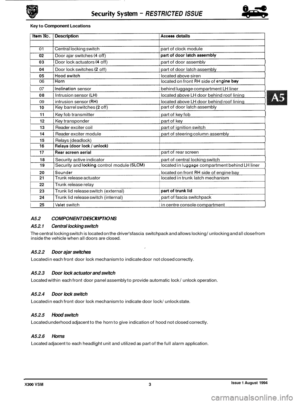
I 03 I Door lock actuators (4 off) 1 part of door assemblv I I
Issue 1 August 1994 X300 VSM 3 I
1 04 I Door lock switches (2 off) I part of door latch assembly I I
1 05 IHoodswitch 1 located above siren I I
1 06 IHorn 1 located on front RH side of en(
1 07 I Inclination sensor I behind luggage compartment LH liner I I
I 08 I Intrusion sensor (LH) I located above LH door behind roof lining I
I 09 I intrusion sensor (RH) 1 located above LH door behind roof lining I
I
1 1 part of door latch assembly I 10 I Key barrel switches (2 off)
1 11 I Key fob transmitter 1 part of key fob I I
I 12 I Key transponder 1 part of key I I
I 13 I Reader exciter coil 1 part of ignition switch I I
I 14 I Reader exciter module 1 part of steering column assembly I I
1 15 I Relays (deadlock) I I I
1 18 I Security active indicator part of central locking switch I I
I 19 I Securitv and lockina control module (SLCM) located in luaaaae compartment behind LH liner I I
1 20 ISounder , located on front RH side of engine bay I I
1 25 IValet switch 1 in centre console compartment I I
A5.2 COMPONENT DESCR/PT/O NS I
stem - RESTRICTED ISSUE
Key to Component Locations
Item No. Description Access details
01 Central locking switch part of clock module
02
1 I
Door ajar switches (4 off)
I I
part of rear screen
I 21 I Trunk release actuator located in trunk latch mechanism
22 I Trunk release relay
23
24 I Trunk lid release switch (external)
I Trunk lid release switch (internal) part of
fascia switchpack ,
A5.2.1 Central locking switch
A5.2.2 Door ajar switches
Located in each front door lock mechanism to indicate door not closed correctly.
-
The central locking switch is located on the driver'sfascia switchpack and allows locking / unlocking and all close from
inside the vehicle when all doors are closed.
A5.2.3
Located within each front door panel assembly to provide automatic lock / unlock operation.
Door lock actuator and switch
A5.2.4 Door lock switch
Located in each front door lock mechanism to indicate door lock/ unlock state.
A5.2.5 Hood switch
Located underhood adjacent to the horn to give indication of hood not closed correctly.
A5.2.6 Horns
Located adjacent to each headlight unit and utilized as part of the full alarm application.