steering JAGUAR XJ6 1994 2.G Service Manual
[x] Cancel search | Manufacturer: JAGUAR, Model Year: 1994, Model line: XJ6, Model: JAGUAR XJ6 1994 2.GPages: 521, PDF Size: 17.35 MB
Page 289 of 521
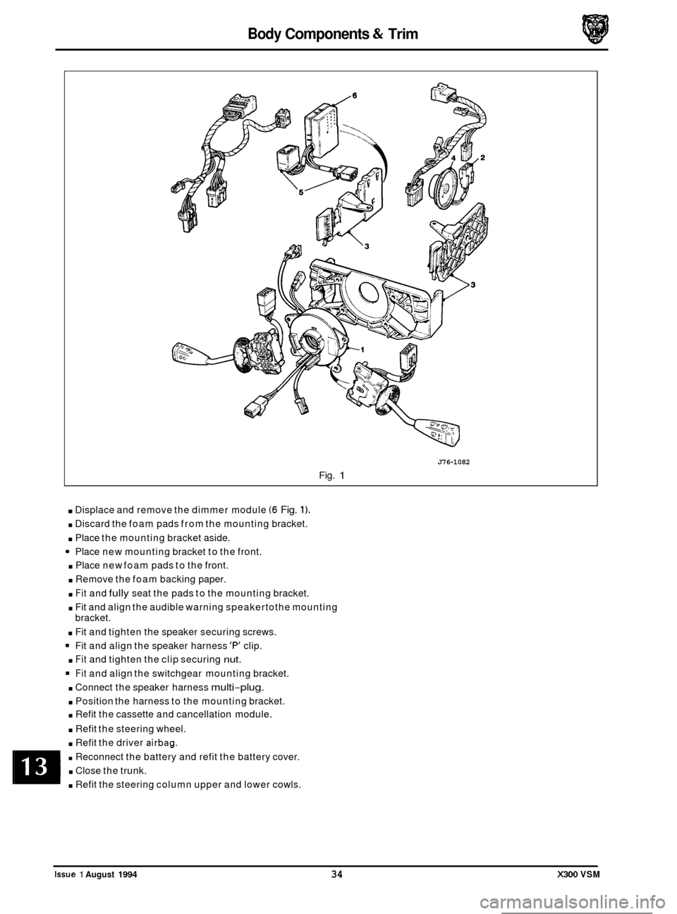
Body Components & Trim
J76-1082
Fig. 1
. Displace and remove the dimmer module (6 Fig. 1).
. Discard the foam pads from the mounting bracket.
. Place the mounting bracket aside.
Place new mounting bracket to the front.
. Place new foam pads to the front.
. Remove the foam backing paper.
. Fit and fully seat the pads to the mounting bracket.
. Fit and align the audible warning speakertothe mounting
bracket.
. Fit and tighten the speaker securing screws.
Fit and align the speaker harness
'F" clip.
. Fit and tighten the clip securing nut.
Fit and align the switchgear mounting bracket.
. Connect the speaker harness multi-plug.
. Position the harness to the mounting bracket.
. Refit the cassette and cancellation module.
. Refit the steering wheel.
. Refit the driver airbag.
. Reconnect the battery and refit the battery cover.
. Close the trunk.
. Refit the steering column upper and lower cowls.
0
0
0
0
Issue 1 August 1994 34 X300 VSM
Page 303 of 521
Body Components & Trim a
13.8 SEATING AND SEAT BELTS
13.8.1 Seating, Description
The front seats are available in a range of materials consisting of sculptured fabric / leather, leather, sports cloth / leather, embossed leather / leather and autolux. Both seats are available as 'manual', ie manually adjustable with elec- tric rise and fall, manual height adjustment headrests, 'power', ie 12-way electric adjustment, 'power with memory', ie memory controlled, 12-way electric adjustment of seat, steering column and exterior rear view mirrors and 'heated',
ie with integral heating.
Front seats are based on a non
-handed, one-piece frame which includes cushion and squab frames and seat adjuster
mechanisms. The seat switchpacks (powerseats) are fitted to the outboard side of driver and passenger seats; on 'man- ual'seats, the seat height adjustment switch is similarly located. Seat control modules SCMs are contained within the
seat assemblies. The seats are secured through four mounting points to the vehicle floor.
Rear seats are of the bench type with
full width removable cushion and individual seat squabs.
Electrical components installed on the heel board below the rear passenger seat are protected
by two covers secured
by two locating brackets on the floor and by two latches on the cover. The latches are released by pushing down on
the two recesses in the top edge of the cover.
13.8.2 Front Manual Seat, Renew
. Disconnect vehicle battery ground lead.
. Disconnect electrical connections as required.
. Remove the seat forward fixings.
Move the seat fully forward.
. Remove the rear fixing / slide covers.
. Remove the seat rear fixings.
. Reposition seat for access and remove seat from vehicle.
. To refit seat, carry out reversal of above procedure.
13.8.3
. Disconnect vehicle battery ground lead.
. Move the seat fully forward to gain access to squab back
Remove squab side fixings, disconnect lamp harness and
. To refit, carry out reversal of the above procedure.
Front Seat (Power Operated) Squab Back
Cover, Renew
cover outer fixings.
remove squab back cover.
13.8.4
. Position seat as required for access.
. Disconnect vehicle battery ground lead.
. Release sound insulation retainers and displace insula-
. Remove SCM cover, move SCM aside and remove seat
. Remove the seat forward fixings and move the seat fully
. Remove the seat rearward fixing covers and remove the
. Disconnect multi-plugs, seat switch and motor harness to
. Release harness tie strap and remove seat assembly from
Front Seat (Power Operated), Renew
tion.
switch
multi-plug from its mounting bracket.
forward. seat rearward fixings.
SCM.
vehicle.
. To refit, carry out reversal of the above procedure, ensur- ing that fixings are tightened to the correct torque.
Issue 1 August 1994 48 X300 VSM
0
0
0
Page 345 of 521
rl Electrical
15.1.6 Fire Hazard Infonnath
Thermal decomposition or combustion may produce dense smoke and other dangerous fumes which in fire situations
form
a highly toxic explosive.
In the event of fire the surrounding area must be evacuated and
all personnel kept well upwind of the area.
Full fire fighting protective gear and
a self contained breathing apparatus operating in the positive pressure mode must
be worn for combating fire. Material near fires must be cooled with water spray to prevent ignition.
Fires should be allowed to burn themselves
out if not threatening to life or property. If fire is threatening to life or prop- erty use copious quantities of water to extinguish.
15.1.7 Ventilath
Local exhaust ventilation designed by a professional engineer should be provided if vapours, fumes, or dusts are gen- erated whilst working with airbag module.
The latest issue of the manual for recommended practices on 'Industrial Ventilation' is available from the
ACGIH Com- mittee on Industrial Ventilation, PO Box 16153, Lansing, MI 48910, USA.
The need for local exhaust ventilation should be evaluated by a professional industrial hygienist.
15.1.8 Respiratory Precauth
To prevent the inhalation of dangerous fumes and dusts, an approved mask should be worn.
15.1.9 Eye Protection
Chemical protective goggles are recommended where there is a possibility of eye contact with the propellant.
Safety glasses with side shields are recommended for
all other operations.
15.1. I0 Protective Clothing
Approved protective gloves, overalls and shoes / boots should be worn.
15.1.1 1 Handling and Storage Precautions
Do not store airbag module near live electrical equipment or circuitry. Store in a dry environment at ambient tempera-
tures.
Good housekeeping and engineering practices should be employed to prevent the generation and accumulation of
dusts. Store in compliance with
all local state and federal regulations.
15.1.12 Driver And Passenger Airbag Modules Assembly / Removal / Service Instructions
Before starting work, ensure ignition switch is in 'IocK position, key is removed and negative terminal cable
is disconnected from the battery.
As the airbag is equipped with a back up power source and due to the risk of airbag being inadvertently
deployed, wait one minute or longer before starting work.
0 Disconnecting the battery cancels the memory for clock, radio, seats, mirrors, steering column and any other
components using battery power. Reset memory after work is completed.
0 Never use airbags from other vehicles, always use new parts.
0 After work is completed, reconnect battery and perform warning light check see diagnostic manual.
0 Never use electrical probes to check voltage or electrical resistance.
0 Disconnect the airbag before carrying out any work on, or in the vicinity of module, or when using electric weld- ing equipment.
0 Always ensure that battery negative has been disconnected for one minute or longer before commencing any
removal procedure.
EB
Issue 1 August 1994 4 X300 VSM
Page 351 of 521
IT Electrical
15.2.8 Odometer
With the ignition 'OFF' the odometer is permanently dis-
played but not illuminated. With the ignition 'ON' the odo- meter is displayed and also illuminated.
Trip information or driver information messages may be dis
-
played instead of the 'ODO'. By pressing the 'ODO' button
once or twice the trip and driver information messages can
be deleted and the
'ODO rdisplayed.
W. The odometer value is not stored within the LCD
module.
15.2.9 Trip Computev
This provides information on the vehicle's speed, fuel usage
and distance traveled
all of which are calculated by a micro
processor.
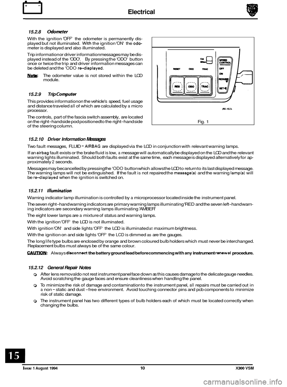
The controls, part of the fascia switch assembly, are located
on the right
-hand side pod positioned to the right-hand side
of the steering column.
I
/
J86-192L
Fig. 1
15.2.10 Driver Information Messages
Two fault messages, FLUID - AIRBAG are displayed via the LCD in conjunction with relevant warning lamps.
If an
airbag fault exists or the brake fluid is low, a message will automatically be displayed on the LCD and the relevant
warning lights illuminated. Should both faults exist at the same time, each message is displayed alternatively for ap
- proximately 2 seconds.
Messages may becancelled
by pressing the 'ODO button which allowsthe LCD to return to its last displayed message.
The warning lamps will not be extinguished. If the fault is not repaired the message(s) and the warning lamp(s) will
be redisplayed when the ignition is switched on.
15.2.11 /llumination
Warning indicator lamp illumination is controlled by a microprocessor located inside the instrument panel.
The seven right
-hand warning indicators are primary warning lamps illuminating 'RED and the seven left-hand warn-
ing indicators are secondary warning lamps illuminating 'AMBER'
The eight lower lamps are
a mixture of status and warning lamps.
With the ignition
'OFF' the LCD is not illuminated.
With ignition
'ON' and side lights 'OFF' the LCD is illuminated at maximum brightness.
With the ignition on and side lights
'OFF' the LCD is dimmed as are the gauges.
The long
life type bulbs are enclosed by orange and brown coloured bulb holders which must never be interchanged.
Replacement bulbs must always be of the same colour.
CAUTIQN: Always dwonnect the battery ground lead before commencing with any instrument rsimwal procedure.
15.2.12 General Repair Notes
0 After lens removal do not rest instrument panel face down as this causes damage to the delicate gauge needles.
Avoid scratching the gauge faces and ensure cleanliness when handling the panel.
0 To minimize the risk of damage and contamination to the instrument panel, all repairs must be carried out in a non - static and dust -free environment. Avoid touching connector pins and pcb components to minimize
risk of static damage.
0 The instrument panel has two different types of bulb holders each of which must be located correctly when
changing the bulbs.
Issue 1 August 1994 10 X300 VSM
Page 357 of 521
15.6
15.6.1
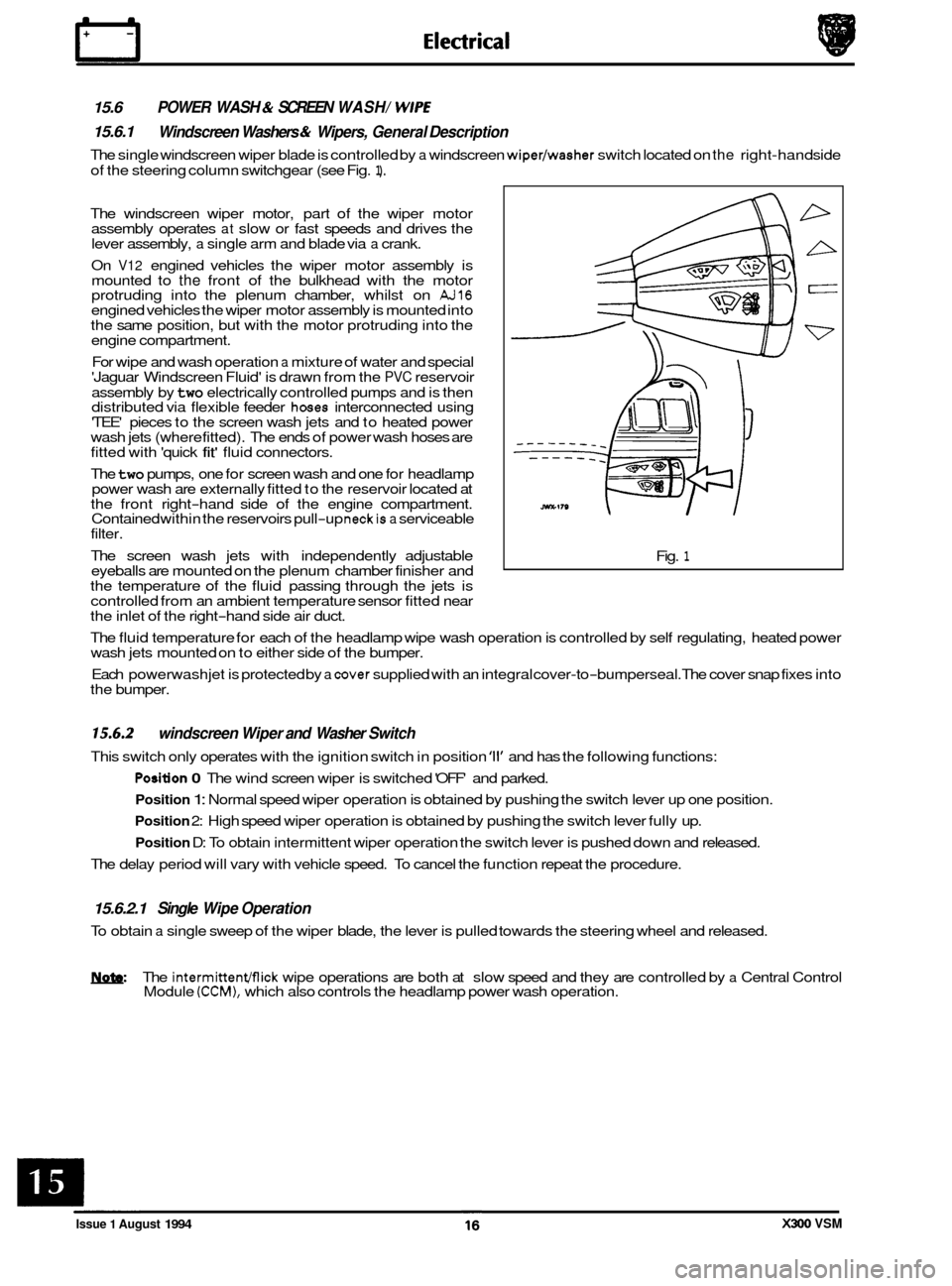
The single windscreen wiper blade is controlled by a windscreen wiper/washer switch located on the right-hand side
of the steering column switchgear (see Fig.
1).
POWER WASH & SCREEN WASH/ WlPE
Windscreen Washers & Wipers, General Description
The windscreen wiper motor, part of the wiper motor
assembly operates at slow or fast speeds and drives the
lever assembly, a single arm and blade via a crank.
On
V12 engined vehicles the wiper motor assembly is
mounted to the front of the bulkhead with the motor
protruding into the plenum chamber, whilst on AJ16 engined vehicles the wiper motor assembly is mounted into
the same position, but with the motor protruding into the
engine compartment.
For wipe and wash operation
a mixture of water and special
'Jaguar Windscreen Fluid' is drawn from the PVC reservoir
assembly by
two electrically controlled pumps and is then
distributed via flexible feeder hoses interconnected using
'TEE' pieces to the screen wash jets and to heated power
wash jets (where fitted). The ends of power wash hoses are
fitted with 'quick
fit' fluid connectors.
The
two pumps, one for screen wash and one for headlamp
power wash are externally fitted to the reservoir located at
the front right
-hand side of the engine compartment.
Contained within the reservoirs pull-up neckis a serviceable
filter.
The screen wash jets with independently adjustable
eyeballs are mounted on the plenum chamber finisher and
the temperature of the fluid passing through the jets is
controlled from an ambient temperature sensor fitted near
the inlet of the right
-hand side air duct. Fig.
1
The
fluid temperature for each of the headlamp wipe wash operation is controlled by self regulating, heated power
wash jets mounted on to either side of the bumper.
Each powerwash jet is protected by
a cover supplied with an integral cover-to-bumperseal. The cover snap fixes into
the bumper.
15.6.2
This switch only operates with the ignition switch in position '11' and has the following functions:
windscreen Wiper and Washer Switch
Position 0 The wind screen wiper is switched 'OFF' and parked.
Position 1: Normal speed wiper operation is obtained by pushing the switch lever up one position.
Position 2: High speed wiper operation is obtained by pushing the switch lever fully up.
Position D: To obtain intermittent wiper operation the switch lever is pushed down and released.
The delay period will vary with vehicle speed. To cancel the function repeat the procedure.
15.6.2.1 Single Wipe Operation
To obtain a single sweep of the wiper blade, the lever is pulled towards the steering wheel and released.
W The intermittenmick wipe operations are both at slow speed and they are controlled by a Central Control
Module (CCM), which also controls the headlamp power wash operation.
Issue 1 August 1994 X300 VSM
Page 375 of 521
I3 E I ectr ical
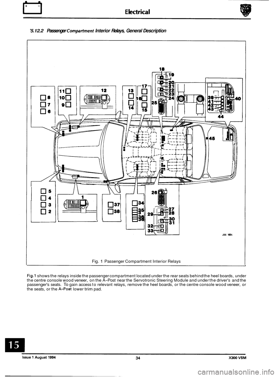
'5.12.2 Passenger Compatiment Interior Relays, General Description
I 0":
03
02
I 1-
03
036 0.i
Fig. 1 Passenger Compartment Interior Relays
J86 1894
0
0
0
Fig.1 shows the relays inside the passenger compartment located under the rear seats behind the heel boards, under
the centre console wood veneer, on the A-Post near the Servotronic Steering Module and under the driver's and the
passenger's seats. To gain access to relevant relays, remove the heel boards, or the centre console wood veneer, or
the seats, or the
A-Post lower trim pad.
Page 380 of 521
86.52.01
86.91 -83
19.75.21
86.80.24
Universal garage door opener
Security
& Locking Control Module
(SLCM)
Sunroof
Mirror memory control
Seat
/ Mirror Memory (Passenger.)
Speed control
Air conditioning
(NCCM)
Transmission control
Engine Management
BPU (Body Processor Unit)
ABS (Anti
-lock Braking System &
Traction Control (where fitted).
(ABS/TC CM)
Bulb failure
Rear
Front
I Power steering
I Column / mirror ECM
Reader exciter
Location
Roof console panel
LH side upper wheel arch, inside the
trunk below fuel filler pipe
Roof console panel.
Mounted inside driver's
& passenger's
seat.
Behind passenger knee bolster.
RH side of air conditioning unit.
Behind passenger knee bolster.
RH side footwell in front of 'A' post
behind cover.
Behind passenger knee bolster.
Engine compartment below
anti-lock
braking system modulator.
Trunk inside electrical carrier box,
Engine compartment behind each
headlamp assembly.
LH side footwell on
'A' post, behind cover.
On the side of steering column.
Around the lock barrel of steering
column.
Behind passenger knee bolster below the
airbag module.
Behind bumper, LHS of vehicle
Numb
11
13
10
9
14
2
RHD
20 LHD
1
16
RHD
(1 2&6)
7 LHD
(12&16)
6 (12&16)
19 RHD
3 LHD
18 RHD
4 RHD
12
22
& 24
17 5
8
15 RHD
23 LHD
21
X300 VSM 39 issue 1 August 1994
Page 382 of 521
Snecif icat ion W -I- ..........
e
0
CON TENTS
Title Page
Specification. 1995 Model Year Vehicles ................................................................... 1
EngineManagementSystem ........................................................................\
. 1
Cooling System ........................................................................\
............ 7
Fuelsystem Pump ........................................................................\
......... 7
Clutch ........................................................................\
................... 7
Manual Transmission Ratios ........................................................................\
. 1
Automatic Transmission Ratios ....................................................................... \
2
Final Drive Unit Ratios ........................................................................\
..... 2
Climate Control System ........................................................................\
..... 2
Braking System ........................................................................\
............ 3
Steering&Suspension ........................................................................\
...... 4
Electrical Equipment ........................................................................\
....... 5
Lubricants & Fluids ........................................................................\
......... 7
Vehicle Weights ........................................................................\
........... 9
Tires ........................................................................\
.................... 10
Snowchains ........................................................................\
............. 17
Bulbs ........................................................................\
................... 12
Fuses ........................................................................\
................... 14
Issue 1 August 1994 AI-95MY i X300 VSM
Page 387 of 521
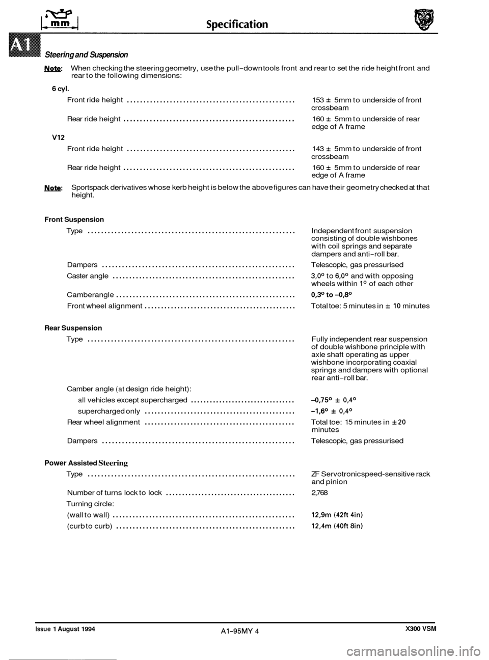
Steering and Suspension
W: When checking the steering geometry, use the pull-down tools front and rear to set the ride height front and
rear to the following dimensions:
Front ride height
................................................... 153 f 5mm to underside of front
crossbeam
Rear ride height
.................................................... 160 f 5mm to underside of rear
edge of A frame
Front ride height
................................................... 143 f 5mm to underside of front
crossbeam
Rear ride height
.................................................... 160 f 5mm to underside of rear
edge of A frame
U: Sportspack derivatives whose kerb height is below the above figures can have their geometry checked at that
height.
Front Suspension
..............................................................
0
Type Independent front suspension
consisting of double wishbones
with coil springs and separate
dampers and anti
-roll bar.
Dampers
.......................................................... Telescopic, gas pressurised
Caster angle
....................................................... 3,0° to 6,0° and with opposing
wheels within Io of each other
Camberangle
...................................................... 0,3°to-0,80
Front wheel alignment .............................................. Total toe: 5 minutes in f 10 minutes
Rear Suspension
Type .............................................................. Fully independent rear suspension of double wishbone principle with
axle shaft operating as upper
wishbone incorporating coaxial
springs and dampers with optional
rear anti
-roll bar.
Camber angle
(at design ride height):
all vehicles except supercharged ................................. -0,75O f 0,4O
supercharged only -1,6O f 0,4O ..............................................
0 Rear wheel alignment .............................................. Total toe: 15 minutes in f20
Dampers .......................................................... Telescopic, gas pressurised
minutes
Power Assisted Steering
Type .............................................................. ZF
Servotronic speed-sensitive rack
and pinion
Number
of turns lock to lock ........................................ 2,768
Turning circle: (wall to wall)
....................................................... 12,9m (42ft 4in)
(curb to curb) ...................................................... 12,4m (40ft 8in)
0
X300 VSM Issue 1 August 1994 AI-95MY 4 ~~~~
Page 390 of 521
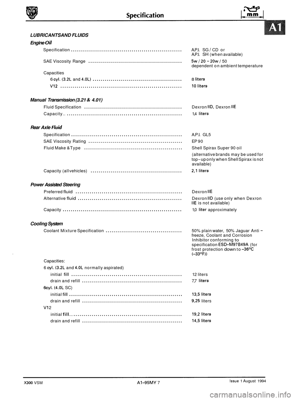
0 LUBRICANTSAND FLUIDS
Engine
Oil
Specification ....................................................... A.P.I. SG I CD or
A.P.I. SH (when available)
SAE Viscosity Range
............................................... 5w 120 - 20w J 50
dependent on ambient temperature
6 cyi. (3.2L and 4.0L) ............................................. 8 liters
VI2 ............................................................ 10liters
Capacities
Manual Transmission (3.21 & 4.01)
Fluid Specification ................................................. Dexron IlD, Dexron IIE
Capacity.. ......................................................... 1,4 liters
Rear Axle Fluid
Specification ....................................................... A.P.I. GL5
Fluid Make &Type
................................................. Shell Spirax Super 90 oil
SAE
Viscosity Rating
............................................... EP 90
(alternative brands may be used for
top
-up only when Shell Spirax is not
available)
0
Capacity (all vehicles) .............................................. 2,l liters
Power Assisted Steering
Preferred fluid ..................................................... Dexron IIE
Alternative fluid .................................................... Dexron IID (use only when Dexron IIE is not available)
Capacity
........................................................... 1,0 liter approximately
Cooling System
Coolant Mixture Specification ....................................... 50% plain water, 50% Jaguar Anti - freeze, Coolant and Corrosion
Inhibitor conforming to specification ESBM97B49A (for
frost protection down to -36OC (-33OF))
Capacities:
6
cyl. (3.2L and 4.OL normally aspirated)
initial
fill ....................................................... 12 liters
drain and refill
.................................................. 7,7 liters
6cyl. (4.0L SC)
initial
fill ........................................................ 13,5 liters
drain and refill .................................................. 9,25 liters
initial
fill.. ...................................................... 19,2 liters
drain and refill .................................................. 14,5 liters
VI 2
Issue 1 August 1994 X300 VSM AI-95MY 7