steering JAGUAR XJ6 1994 2.G Owner's Guide
[x] Cancel search | Manufacturer: JAGUAR, Model Year: 1994, Model line: XJ6, Model: JAGUAR XJ6 1994 2.GPages: 521, PDF Size: 17.35 MB
Page 246 of 521
Brakes
12.7 HYDRAULICCONTROL MODULE- RENEW
SRO 70.60.18
70.60.1
9
Refer to Section 12.4, Brake System Bleeding before carrying out this procedure. Pay particular attention to the warn- ings and cautions relating to brake fluid, cleanliness and cleaning materials.
W: The illustration shows the hydraulic control module of a 6 cyl. vehicle with traction control. Hydraulic control
modules on non-traction control vehicles have only three outlet ports. Apart from this, the removal procedure
is the same for all vehicles.
. Raise the vehicle.
Displace the bleeder screw dust cap of the front LH caliper.
The dust cap will remain captive
on the bleed screw.
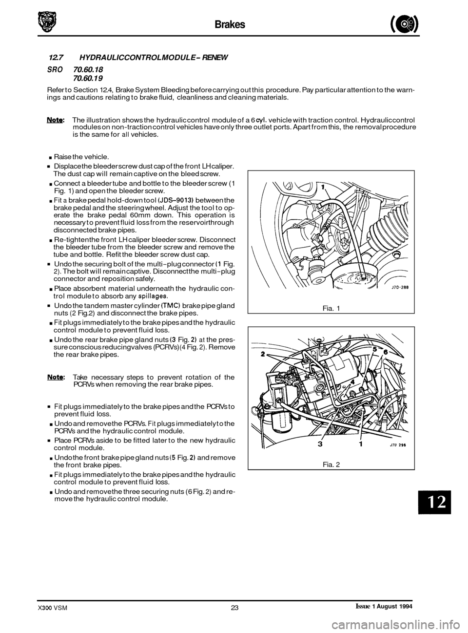
. Connect a bleeder tube and bottle to the bleeder screw (1
Fig. 1) and open the bleeder screw.
. Fit a brake pedal hold-down tool (JDS-9013) between the
brake pedal and the steering wheel. Adjust the tool to op
- erate the brake pedal 60mm down. This operation is
necessary to prevent fluid loss from the reservoirthrough
. Re-tighten the front LH caliper bleeder screw. Disconnect
the bleeder tube from the bleeder screw and remove the
tube and bottle. Refit the bleeder screw dust cap.
Undo the securing bolt of the multi-plug connector (1 Fig. 2). The bolt will remain captive. Disconnect the multi-plug
connector and reposition safely.
. Place absorbent material underneath the hydraulic con-
trol module to absorb any spillages.
Undo the tandem master cylinder CTMC) brake pipe gland
nuts (2 Fig.2) and disconnect the brake pipes.
. Fit plugs immediately to the brake pipes and the hydraulic
control module to prevent fluid
loss.
. Undo the rear brake pipe gland nuts (3 Fig. 2) at the pres- sure conscious reducing valves (PCRVs) (4 Fig. 2). Remove
the rear brake pipes.
disconnected brake pipes.
Note: Take necessary steps to prevent rotation of the
PCRVs when removing the rear brake pipes.
Fit plugs immediately to the brake pipes and the PCRVs to
. Undo and remove the PCRVs. Fit plugs immediately to the
Place PCRVs aside to be fitted later to the new hydraulic
. Undo the front brake pipe gland nuts (5 Fig. 2) and remove
. Fit plugs immediately to the brake pipes and the hydraulic
. Undo and remove the three securing nuts (6 Fig. 2) and re-
0 prevent fluid loss.
PCRVs and the hydraulic control module.
control module.
the front brake pipes.
control module to prevent fluid
loss.
move the hydraulic control module. Fia.
1
3 1 J70 296
Fia. 2
Issue 1 August 1994 X300 VSM 23
Page 248 of 521
Brakes
12.8
SRO 70.60.21
PRESSURE CONSCIOUS REDUCING VALVES - RENEW
Refer to Section 12.4, Brake System Bleeding before carrying out this procedure. Pay particular attention to the warn- ings and cautions relating to brake fluid, cleanliness and cleaning materials.
Note: The illustration shows the hydraulic control module of a 6 cyl. vehicle with traction control. Hydraulic control
modules on non-traction control vehicles have only three outlet ports. Apart from this, the removal procedure
is the same for all vehicles.
. Raise the vehicle.
Displace the bleeder screw dust cap of the front LH caliper.
The dust cap will remain captive on the bleed screw.
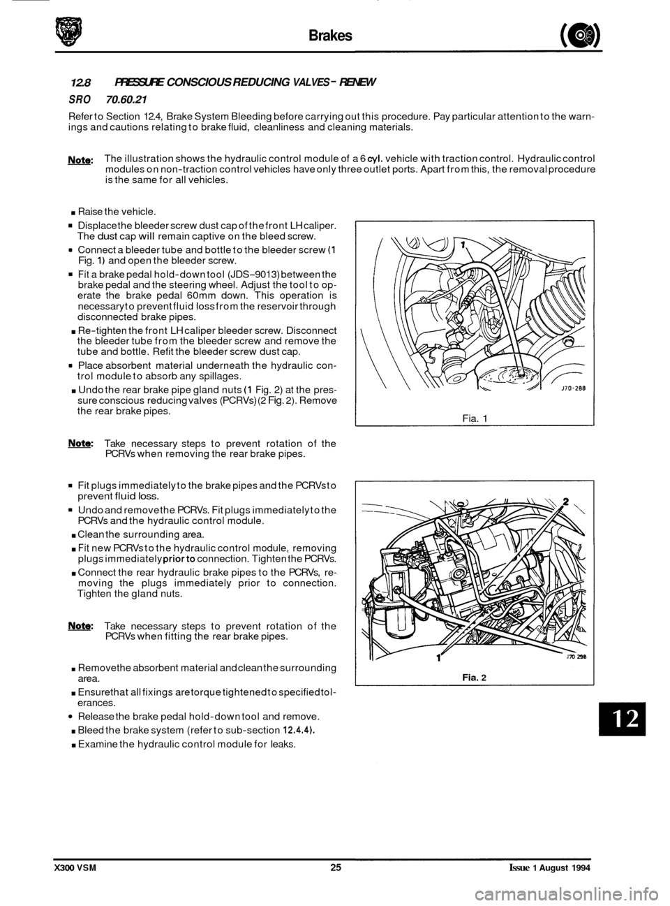
rn Connect a bleeder tube and bottle to the bleeder screw (1 Fig. 1) and open the bleeder screw.
Fit a brake pedal hold-down tool (JDS-9013) between the
brake pedal and the steering wheel. Adjust the tool to op- erate the brake pedal 60mm down. This operation is
necessary to prevent fluid
loss from the reservoir through
disconnected brake pipes.
. Re-tighten the front LH caliper bleeder screw. Disconnect
the bleeder tube from the bleeder screw and remove the
tube and bottle. Refit the bleeder screw dust cap.
rn Place absorbent material underneath the hydraulic con- trol module to absorb any spillages.
. Undo the rear brake pipe gland nuts (1 Fig. 2) at the pres- sure conscious reducing valves (PCRVs) (2 Fig. 2). Remove
the rear brake pipes.
m: Take necessary steps to prevent rotation of the
PCRVs when removing the rear brake pipes.
Fit plugs immediately to the brake pipes and the PCRVs to
Undo and remove the PCRVs. Fit plugs immediately to the
. Clean the surrounding area.
. Fit new PCRVs to the hydraulic control module, removing
plugs immediately priorto connection. Tighten the PCRVs.
. Connect the rear hydraulic brake pipes to the PCRVs, re- moving the plugs immediately prior to connection.
Tighten the gland nuts.
prevent
fluid loss.
PCRVs
and the hydraulic control module.
0
Note: Take necessary steps to prevent rotation of the
PCRVs when fitting the rear brake pipes.
. Removethe absorbent material and clean the surrounding
. Ensure that all fixings are torque tightened to specified tol-
Release the brake pedal hold-down tool and remove.
. Bleed the brake system (refer to sub-section 12.4.4).
. Examine the hydraulic control module for leaks.
area.
erances. Fia.
1
Fia. 2
X300 VSM 25 Issue 1 August 1994
Page 251 of 521
SECTION CONTENTS
Sub-Section Title SRO Page
13.3.19 .......... Underscuttle Pad. Drivers Side. Remove for Access and Refit .......... 76.46.1 1/90 ......... 26
13.3.20
.......... Underscuttle Pad. Passenger Side. Remove for Access and Refit ....... 76.46.15/90 ......... 26
13.3.21
.......... Fascia Closing Panel - Passenger Side. Renew ...................... 76.46.27 ............ 27
13.3.22
.......... Fascia Closing Panel -Drivers Side. Renew ......................... 76.46.28 ............ 27
13.3.23
.......... Fascia Center Veneer Panel. Renew ............................... 76.47.06 ............ 28
13.3.24
.......... Console Finisher Veneer Panel. Renew ............................ 76.47.26 ............ 29
13.3.25 .......... Console Ashtray Lid Veneer Panel. Renew ......................... 76.47.27 ............ 30
13.3.26 .......... Console Ashtray Surround Veneer Panel. Renew .................... 76.47.28 ............ 30
13.3.27
.......... Console Rear Extension Veneer Panel. Renew ...................... 76.47.30 ............ 30
13.3.28 .......... Console Ashtray, Renew ......................................... 76.67.18 ............ 31
13.3.29
.......... Steering Column Upper cowl. Renew ............................. 76.46.02 ............ 32
13.3.30
.......... Steering Column Lower cowl. Renew ............................. 76.46.03 ............ 32
13.3.3
1 .......... Steering Column Switchgear Mounting Bracket. Renew .............. 76.46.33 ............ 33
13.3.32
.......... 'A' Post Lower Trim Pad. Renew .................................. 76.13.30 ............ 35
13.3.33
.......... Rear Quarter Upper Trim Pad. Renew .................................................. 35
13.3.34
.......... 'B' Post Upper Trim Pad. Renew ....................................................... 35
13.3.35 .......... 'B' Post Lower Trim Pad. Renew ....................................................... 35
13.3.36 .......... Handbrake Lever Trim. Renew ........................................................ 35
13.3.37
.......... Combined Grab Handle and Coat Hanger Hook. Renew .................................. 35
13.3.38
.......... Sun Visor Assembly RH or LH. Renew .................................................. 36
13.3.39
.......... Roof Lining (Headlining). Description .................................................. 37
13.3.40
.......... Roof Lining. Renew ................................................................. 37
13.4 ............. Trunk ........................................................................\
..... 38
13.4.1
............ Trunk. Description .................................................................. 38
13.4.2.
........... Trunk Side Liner - Left Hand. Renew .............................. 76.19.22 ............ 39
13.4.3
............ Trunk Side Liner - Right Hand. Renew ............................. 76.19.23 ............ 39
13.4.4
............ Trunk Floor Carpet. Renew ...................................... 76.19.30 ............ 39
13.4.5.
........... Trunk Front Liner, Renew ........................................ 76.19.3 1 ............ 39
13.4.6.
........... Trunk Seal Retainer, Renew ...................................... 76.19.44 ............ 40
13.4.7.
........... Trunk Lid Striker, Adjust .............................................................. 40
13.4.8
............ Trunk Lid Liner, Renew ............................................................... 40
13.4.9
............ Trunk Seal Retainer, Renew ........................................................... 40
13.4.10
.......... Trunk Lid Lock Striker, Renew ......................................................... 40
13.4.11
........... Trunk Lid Lock Barrel. Renew ......................................................... 40
13.4.12
.......... TrunkLidLockMechanism. Renew .................................................... 41
13.3.13
.......... Trunk Lid Gas Strut. Adjust. Renew .................................................... 41
13.4.14
.......... Trunk LidHinge. Renew .............................................................. 41
13.4.15 .......... Trunk Rear Liner, Renew ............................................................. 41
13.5
............. Hood ........................................................................\
..... 42
13.5.1
............ Hood Description ................................................................... 42
13.5.2
............ Plenum Chamber Finisher, Renew ................................ 76.10.01 ............ 42
13.5.3 ............ Hinge. Renew ...................................................................... 42
13.5.4
............ Gasstrut. Renew .................................................................... 43
13.5.5
............ HoodLockRHorLH. Renew ......................................................... 43
issue 1 August 1994 X300 VSM
Page 256 of 521
Body Components & Trim
13.1 GENERAL DESCRIPTION
This section covers the following areas of the vehicle body:
0 Battery cover
0 Carpets - passenger compartment, trunk
0 Console - including radio, glovebox
0 Doors -frames, sealing, locks, trim, glazing
0 Fascia
0 Fuel filler flap assembly
0 Footrest
0 Hood - liners, gas strut, locking,
0 Illuminated sunvisor - inc mirror
0 Interior trim - trim pads, finishers, veneers
0 Mirrors - internal, external
0 Rear parcel tray
0 Roof console
0 Roof lining (headlining)
o Seats -front, rear -
0 Seat belts - front, rear
0 Sliding roof
0 Steering column cowl
0 Underscuttle pad
Refer to Appendix
A4 - Body Systems & Body Repair for information relating to crash-damage repairs and to the fol- lowing external components: exterior trim, bumpers, windscreen and rear screen, closures and sealing.
Refer to Section 15, Electrical for details of the following motors and solenoids: driver's and interior mirrors, window
lift, sunroof, seat / headrest and locking mechanisms (doors, trunk and filler cap).
Refer to Section 15, Electrical and Electrical Diagnostic Manual (EDM) for details of the passenger and driver airbags.
X300 VSM 1 Issue 1 August 1994
Page 276 of 521
Body Components & Trim ~
issue 1 August 1994 X300 VSM 21
13.3.17 Fascia Board, Renew
SRO 76.46.01
. Remove
the battery cover and disconnect the battery.
Remove the drivers side and passenger side underscuttle
pads, see sub
-sections 13.3.19 and 13.3.20.
. Remove the drivers airbag module, see section 15.5.
Remove the steering wheel, section 10.
Remove the drivers side and passenger side fascia closing
. Remove the fascia center veneer panel, see subsection
Remove the fascia board for access, see subsection
. Disconnect the air conditioning differential potentiometer
Remove the differential potentiometer assembly.
. Displace and reposition the through panel connectors
from the fascia assembly.
. Displace the fascia vent motor / gearbox assemblies har- ness multi-plug from the mounting bracket.
. Disconnect and reposition the fascia harness to console
harness
multi-plug from the mounting bracket.
. Disconnect the BPU harness multi-plugs.
Remove the tiestraps securing the harness to the fascia.
. Reposition the fascia on a bench.
= Displace and reposition the solar sensor assembly from
Disconnect the solar sensor harness multi-plug.
Remove the solar sensor assembly.
= Undo and remove the defrost vents securing screws.
Displace and reposition the defrost vent assemblies.
. Disconnect the tweeter speaker harness multi-plugs.
. Remove the defrost vent assemblies.
. Displace the fascia harness grommet from the fascia.
. Route the harness through the aperture.
Remove the fascia harness assembly.
. Undo and remove passenger airbag deployment door to
fascia securing bolts ( one bolt is removed with the fascia).
. Displace and remove the deployment door assembly.
. Undo and remove the passenger airbag module to fascia
. Displace and remove the airbag module assembly.
. Undo and remove the airbag module I BPU mounting
bracket assembly to fascia securing nuts 1 bolts.
= Displace and remove the mounting bracket assembly.
. Retrieve the spacing washers.
. Displace and remove the side vent outlets from the fascia.
. Displace and remove the side vent ducts securing clips.
. Displace and remove the side vent ducts.
. Undo and remove the center vent flap assembly to fascia
. Displace and remove the center vent flap assembly.
Undo and remove fascia location bracket securing nuts.
Displace and remove the location bracket.
panels, see
sub
-sections 13.3.22 and 13.3.21.
13.3.23. 13.3.17.
harness multi
-plug.
the fascia.
securing bolts.
securing nuts.
Page 278 of 521
Body Components & Trim
. Reposition and fit the motor/gearbox assemblies harness
. Fully seat the through panel connectors to the fascia.
. Place the air conditioning differential potentiometer to the
fascia and route the differential potentiometer harness
through the vent aperture.
. Reconnect the differential potentiometer harness multi-
Plug.
Refit the fascia board.
. Refit the center veneer panel.
. Refit the fascia closing panels.
. Refit the steering wheel.
. Refit the drivers airbag module.
. Refit the underscuttle pads.
. Reconnect the battery and refit the battery cover.
multi
-plug
to the mounting bracket.
X300 VSM 23 Issue 1 August 1994
Page 279 of 521
~~ Body Components & Trim
e 13.3.18 Fascia 6oard - Remove
For Access And Refit
SRO 76.46.01/90
. Remove the battery cover. Disconnect the battery.
Remove the drivers side and passenger side underscuttle
. Remove the drivers airbag module, see section 15.5.
. Remove the steering wheel, section 10.
9 Remove the drivers side fascia closing panel, see sub-sec-
. Remove the passenger side fascia closing panel, see sub-
. Remove the fascia center veneer panel, see subsection
. Undo and remove the fascia tie bar securing nuts.
. Displace the tie bars.
. Undo and remove the instrument housing /fascia switch-
. Reposition the multi-plug mounting bracket.
. Disconnect the steering column control module multi-
. Disconnect the fascia switchpack harness multi-plugs.
. Displace and reposition the instrument pack for access.
. Disconnect the instrument pack harness multi-plugs.
. Remove the instrument pack / fascia switchpack assem-
. Disconnect the right hand fascia harness to cabin harness
. Disconnect the column switchgear and column motors
Disconnect the ignition switch harness multi-plug.
. Disconnect the exciter coil harness multi-plug.
. Disconnect the speaker tweeter harness multi-plug.
. Disconnect the speed control control module harness
. Undo and remove the fascia to center console securing
. Displace and remove the passenger side outlet duct.
. Disconnect the fascia harness to console harness multi-
9 Disconnect the let3 hand fascia harness to cabin harness
. Undo and remove the fascia ground eyelets to bodysecur-
. Displace and reposition the ground eyeletsfrom the stud.
. Displace and reposition the airbag control module from
Undo and remove the fascia assembly lower securing nut.
. Undo and remove the fascia outer body bracket to fascia
Carefully displace the fascia rearwards.
pads, see
sub
-sections 13.3.19 and 13.3.20.
tion 13.3.22.
section 13.3.21.
13.2.23.
pack securing screws.
0 plugs.
bly.
multi
-plug.
harness multi
-plug.
multi
-plug.
screws.
0 plugs.
multi
-plug.
ing nut.
the mounting bracket.
securing bolts.
m
0
X300 VSM Issue 1 August 1994 24
Page 280 of 521
Body Components & Trim -
. From behind the fascia passenger side, disconnect the
passenger airbag harness multi-plug.
. With assistance, remove the fascia from the vehicle and
place on a suitably protected bench.
Place the fascia
in position in the vehicle with the center
location peg correctly engaged.
Reconnect the passenger airbag module harness multi-
Plug.
. Carefully fit and align the fascia to the mounting position.
. Fit and tighten the fascia to outer body brackets securing
bolts.
Fit and tighten the fascia assembly lower securing nut.
Reposition and
fit the airbag control module to the mount-
ing bracket.
Reposition and fit the fascia harness ground eyelets to the
ground stud.
Fit and tighten the ground eyelet securing
nut.
harness multi-plug. . Reconnect the left hand fascia harness to cabin housing
. Reconnect the fascia harness to console harness multi- plugs.
Fit and align the passenger side outlet duct.
. Fit and tighten the fascia to console securing screws.
. Reconnect the speed control harness multi-plug.
. Reconnect the speaker tweeter harness multi-plug.
. Reconnect the exciter coil harness multi-plug.
Reconnect the column switchgear and column motor har-
. Reconnect the right hand fascia harness to cabin harness
. Place the instrument pack / fascia switchpack in position.
. Reconnect the instrument pack harness multi-plugs.
. Reposition and fitthe instrument packassemblytothefas-
cia.
Reconnect the fascia switchpack harness multi-plugs.
Reconnect the steering column harness multi
-plugs.
. Reposition and fit the switchpack harness multi-plug mounting bracket.
ness
multi
-plugs.
multi-plug.
. Fit and tighten the instrument pack/ switchpack securing
bolts.
- Fit and align the fascia tie bars.
. Fit and tighten the tie bar securing nuts.
9 Refit the center veneer panel.
Refit the fascia closing panels.
. Refit the steering wheel.
. Refit the drivers airbag module.
. Refit the underscuttle pads.
. Reconnect the battery and refit the battery covers.
Issue 1 August 1994 X300 VSM 25
Page 287 of 521

Body Components & Trim -
13.3.29 Steering Column Upper Cowl, Renew
SRO 76.46.02
Motor the drivers seat fully rearward.
Undo and remove the lower cowl fixing screws (1 Fig. 1).
. Displace and reposition the lower cowl (2 Fig. 1); discard
the ignition lock rubber gaiter
(3 Fig. 1).
. Motor the steering column fully upwards.
Undo and remove the upper column securing screws.
Motor the column fully downwards.
Displace and remove the upper cowl (4 Fig. 1).
Fit and align the new cowl into position.
. Motor the column fully upwards.
. Fit and tighten the cowl securing screws.
9 Fit a new ignition lock rubber gaiter and position the lower
. Fit and tighten the cowl securing screws.
. Motor the column to the original position.
cowl to
the steering column.
13.3.30 Steering Column Lower Cowl, Renew
SRO 76.46.03
= Motor the drivers seat fully rearwards.
. Undo and remove the lower column cowl securing screws
. Displace and reposition the lower cowl (2 Fig. 1).
. Disconnect the rheostat multi-plug (5 Fig. 1).
. Disconnect the tilt column harness multi-plug from the tilt
= Remove the cowl and place to the front; remove the igni-
Displace and remove the rheostat adjusting knob (7 Fig. 1).
. Undo and remove the rheostat securing screws (8 Fig. 1).
. Displace the tilt column switch retaining tangs and re-
move the switch.
. Place the cowl aside.
. Place the new lower cowl to the front.
. Fit and fully seat the column switch.
. Fit and align the rheostat. Fit and tighten the rheostat se-
. Fit and fully seat the rheostat knob.
Fit new ignition switch rubber gaiter and reposition the
. Connect the rheostat harness multi-plug.
. Connect the column switch harness multi-plug.
. Position the cowl to the steering column.
. Fit and tighten the cowl securing screws.
. Motor the seat to the original position.
(1 Fig. 1).
column switch (6 Fig. 1).
tion lock rubber gaiter and discard (3 Fig. 1).
curing screws.
lower cowl.
0
0
0
0
Issue 1 August 1994 32 X300 VSM
Page 288 of 521
Body Components & Trim -
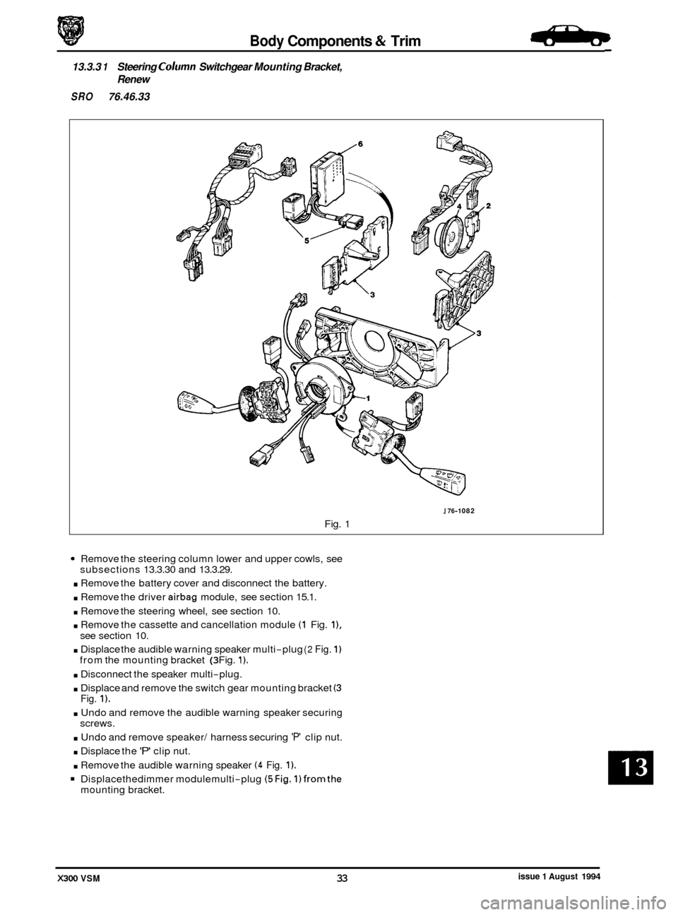
13.3.3 1 Steering Column Switchgear Mounting Bracket,
Renew
SRO 76.46.33
J 76-1 082
Fig. 1
Remove the steering column lower and upper cowls, see
. Remove the battery cover and disconnect the battery.
. Remove the driver airbag module, see section 15.1.
. Remove the steering wheel, see section 10.
. Remove the cassette and cancellation module (1 Fig. I),
. Displace the audible warning speaker multi-plug (2 Fig. 1)
. Disconnect the speaker multi-plug.
. Displace and remove the switch gear mounting bracket (3
. Undo and remove the audible warning speaker securing
. Undo and remove speaker/ harness securing 'P' clip nut.
. Displace the 'P' clip nut.
. Remove the audible warning speaker (4 Fig. 1).
Displacethedimmer modulemulti-plug (5Fig. 1)fromthe
subsections 13.3.30 and 13.3.29.
see section 10.
from the mounting bracket
(3 Fig. 1).
Fig. 1).
screws.
mounting bracket.
issue 1 August 1994 X300 VSM 33