dip JAGUAR XJ6 1994 2.G Workshop Manual
[x] Cancel search | Manufacturer: JAGUAR, Model Year: 1994, Model line: XJ6, Model: JAGUAR XJ6 1994 2.GPages: 521, PDF Size: 17.35 MB
Page 12 of 521
Introduction
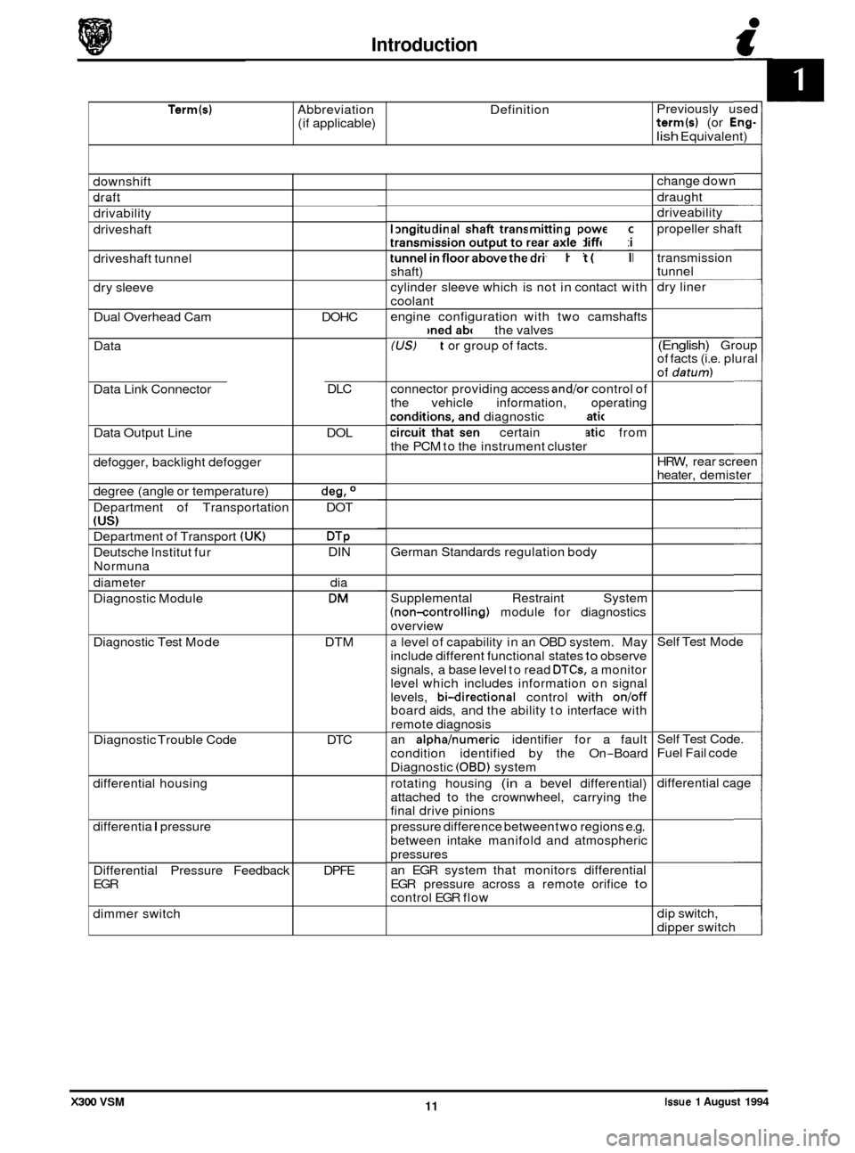
Term(s) Abbreviation Definition
(if applicable) Previously
used term(s) (or Eng-
lish Equivalent)
downshift
draft _.
drivability
driveshaft
driveshaft tunnel
dry sleeve
Dual Overhead Cam
Data
Data Link Connector
Data Output Line
defogger, backlight defogger
degree (angle or temperature)
Department of Transportation
(US)
Department of Transport (UK)
Deutsche lnstitut fur
Normuna
diameter
Diagnostic Module
Diagnostic Test Mode
Diagnostic Trouble Code
differential housing
differentia
I pressure
Differential Pressure Feedback
EGR
dimmer switch DOHC
DLC
DOL
deg, O
DOT
DTP DIN dia
DM
DTM
DTC
DPFE longitudinal
shaft transmitting power from
transmission output to rear axle differential
tunnel
in floor above the driveshaft (propeller
shaft)
cylinder sleeve which is not in contact with
coolant
engine configuration with two camshafts
positioned above the valves
(US) Fact or group of facts.
connector providing access
andlor control of
the vehicle information, operating
conditions, and diagnostic information
circuit that sends certain information from
the PCM to the instrument cluster
German Standards regulation body
Supplemental Restraint System
(non-controlling) module for diagnostics
overview
a level of capability in an OBD system. May
include different functional states
to observe
signals, a base level to read
DTCs, a monitor
level which includes information on signal
levels,
bi-directional control with onloff board aids, and the ability to interface with
remote diagnosis
an
alphahumeric identifier for a fault
condition identified by the On
-Board
Diagnostic
(OBD) system
rotating housing
(in a bevel differential)
attached to the crownwheel, carrying the
final drive pinions
pressure difference between two regions e.g.
between intake manifold and atmospheric
pressures
an EGR system that monitors differential
EGR pressure across a remote orifice
to control EGR flow change
down
draught
driveability
propeller shaft
transmission
tunnel
dry liner
(English) Group
of facts (i.e. plural
of
datum)
HRW, rear screen
heater, demister
Self Test Mode
Self Test Code.
Fuel Fail code
differential cage
dip switch,
dipper switch
Issue 1 August 1994 11 X300 VSM
Page 44 of 521
Engine
3.1.3 ENGINE OIL, RENEW
SRO 12.60.00
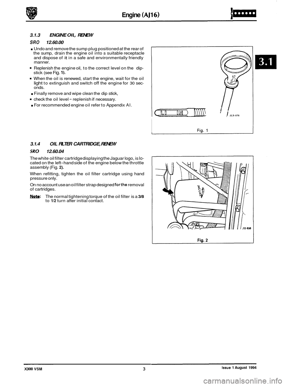
. Undo and remove the sump plug positioned at the rear of
the sump, drain the engine oil into a suitable receptacle
and dispose of
it in a safe and environmentally friendly
manner.
Replenish the engine oil, to the correct level on the dip-
stick (see Fig. 1).
When the oil is renewed, start the engine, wait for the oil
light to extinguish and switch off the engine for 30 sec- onds.
. Finally remove and wipe clean the dip stick,
check the oil level - replenish if necessary.
. For recommended engine oil refer to Appendix AI.
3.1.4 OIL FILTER CARTRIDGE, RENEW
SRO 12.60.04
The white oil filter cartridge displaying the Jaguar logo, is lo- cated on the left-hand side of the engine below the throttle
assembly (Fig. 2).
When refitting, tighten the oil filter cartridge using hand
pressure only.
On no account use an oil filter strap designed
forthe removal
of cartridges.
m: The normal tightening torque of the oil filter is a 3/8 to 1/2 turn after initial contact.
1 JLX-076
Fig. 1
-~ ~ ~~~~~ Issue 1 August 1994 X300 VSM 3
Page 50 of 521
Engine (V12)
3.2.3 ENGINE OIL, RENEW
SRO 12.60.00
. Undo and remove the sump plug positioned at the rear of
the sump, drain the engine oil into a suitable receptacle
and dispose of
it in a safe and environmentally friendly
manner.
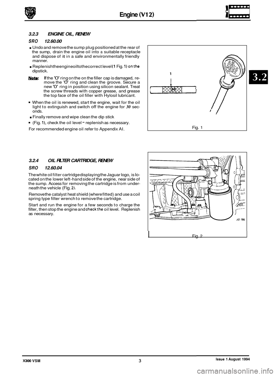
. Replenishtheengineoiltothecorrect level (1 Fig. 1) onthe
dipstick.
1ynfa: If the '0' ring on the on the filler cap is damaged, re- move the '0' ring and clean the groove. Secure a
new '0' ring in position using silicon sealant. Treat
the screw threads with copper grease, and grease
the top face of the oil filler with Hylosil lubricant.
When the oil is renewed, start the engine, wait for the oil
light to extinguish and switch off the engine for 30 sec- onds.
. Finally remove and wipe clean the dip stick
(Fig. l), check the oil level - replenish as necessary.
For recommended engine oil refer to Appendix AI. Fig.
1
3.2.4
OIL FILTER CARTRIDGE, RENEW
SRO 12.60.04
The white oil filter cartridge displaying the Jaguar logo, is lo- cated on the lower left-hand side of the engine, near side of
the sump. Access for removing the cartridge is from under- neath the vehicle (Fig. 2).
Remove the catalyst heat shield (where fitted) and use a coil
spring type filter wrench to remove the cartridge.
Start and run the engine for a few seconds to charge the
filter, then stop the engine and
checkthe oil level. Replenish
as necessary.
I Fig. 2
Issue 1 August 1994 X300 VSM 3
r
Page 137 of 521
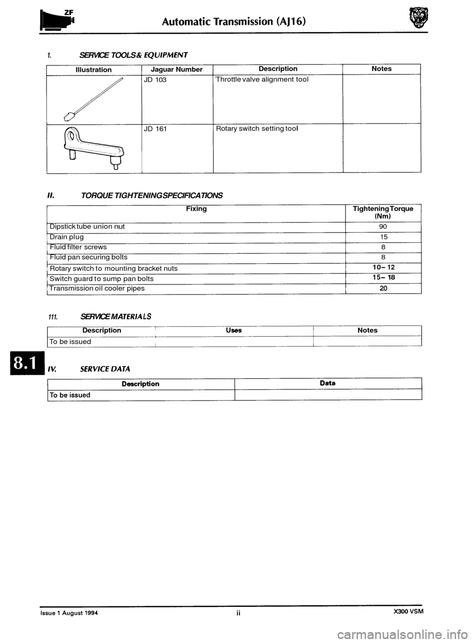
1. SERVICE TOOLS & fQUlPMENT
Illustration
::(())(((((
Jaguar Number
JD 103
JD 161
Description Notes
Throttle valve alignment tool
Rotary switch setting tool
11. TORQUE TIGHTENING SPECIFICATIONS
Fixing Tightening Torque
(Nm)
Dipstick tube union nut 90
Drain plug 15
Fluid filter screws 8
Fluid pan securing bolts 8
Rotary switch to mounting bracket nuts
Transmission oil cooler pipes
20
10- 12
15- 18 Switch guard to sump pan bolts
111. SERVICE MA TERlA L S
Description USeS Notes
To be issued
Page 138 of 521
Automatic Transmission (AJ16)
8.1.1 GENERAL DESCRIPTION
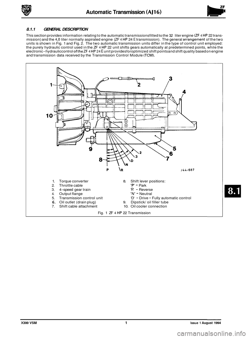
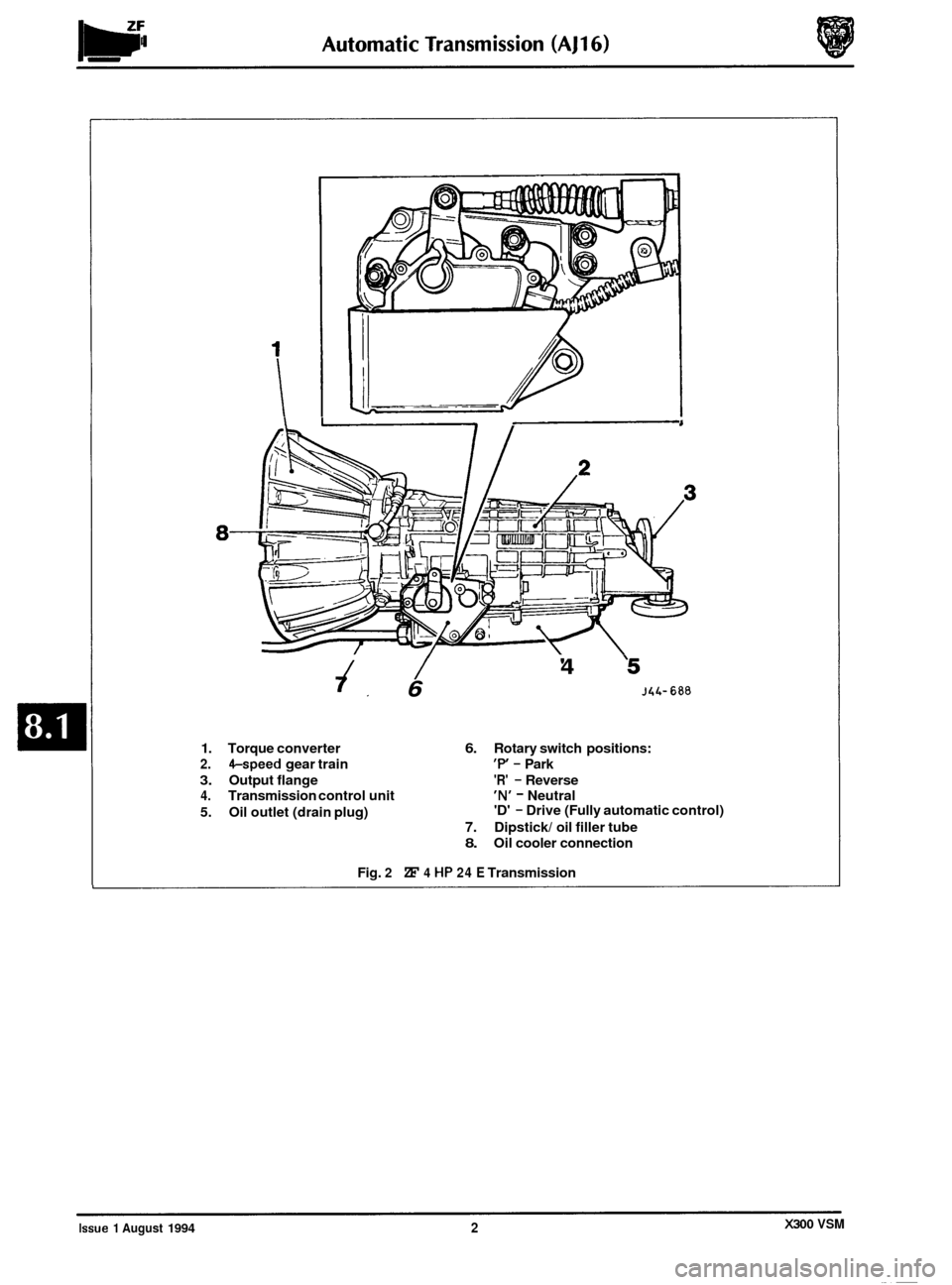
’ This section provides information relating to the automatic transmissionsfitted to the 3,2 liter engine (ZF 4 HP 22 trans- mission) and the 4,O liter normally aspirated engine (ZF 4 HP 24 E transmission). The general arrangement of the two
units is shown in Fig. 1 and Fig. 2. The two automatic transmission units differ in the type of control unit employed:
the purely hydraulic control used in the ZF 4 HP 22 unit shifts gears automatically at predetermined points, while the
electronic-hydrauliccontrol oftheZF 4 HP 24 E unit providesforoptimized shift point sand shift quality based on engine
and transmission data received by the Transmission Control Module (TCM).
P \R J44-607
1. Torque converter 8. Shift lever positions:
2. Throttle cable
‘P - Park
3. 4
-speed gear train ‘R‘ - Reverse
4. Output flange ‘N’ - Neutral
5. Transmission control unit
6. Oil outlet (drain plug) 9. Dipstick/ oil filler tube
7. Shift cable attachment 10. Oil cooler connection
‘D‘
- Drive - Fully automatic
control
Fig. 1 ZF 4 HP 22 Transmission
X300 VSM 1 Issue 1 August 1994
Page 139 of 521
I 1 I
8-
/ /
7, 6
'4 '5
J4L- 688
1. Torque converter 6. Rotary switch positions:
2. &speed gear train 'P - Park
3. Output flange 'R' - Reverse
4. Transmission control unit 'N' - Neutral
5. Oil outlet (drain plug) 'D' - Drive
(Fully automatic control)
7. Dipstick/ oil filler tube
8. Oil cooler connection
Fig.
2 ZF 4 HP 24 E Transmission
X300 VSM Issue 1 August 1994 2
Page 143 of 521
bZF Automatic Transmission (AJ16) -
0
8.1.2 TRANSMISSION FLUID, RENEW
SRO 44.24.02
= Raise the hood and fit a fender cover.
. Raise the vehicle on a ramp.
. Place a drain tin in position beneath the transmission drain
Release and remove the transmission drain plug; allow
. Fit the drain plug with a new washer and torque tighten.
Reposition the drain tin beneath the dipstick tube union.
Remove the screw securing the dipstick tube bracket.
. Release the dipstick tube union nut and disconnect the
tube from the fluid pan.
. Drain the transmission fluid.
Clean the tube unions, reconnect the dipstick tube to the
. Lower the vehicle on the ramp.
. Remove the transmission dipstick.
. Renew the transmission fluid filter, see Subsection 8.1.6.
Fill the transmission with the correct fluid, see the ZF Auto-
Note: It will not be possible to get all the initial fill quantity
of fluid into the transmission.
. Refit the dipstick.
. Startthe engine, apply all brakes and run the transmission
With the engine still running, remove the dipstick.
Clean the dipstick and refit.
Remove the dipstick and check the transmission fluid
. Add fluid until the correct level is achieved.
. Stop the engine and refit the dipstick.
. Checkfluidleveltothe'HOT'marksaftera20mileroad run
(3,2L AND 4,OL)
Plug.
the fluid to drain.
fluid pan and torque tighten the union nut.
0
matic Transmissions Service Manual, General Data.
through
all gear positions and select 'Park'.
level. Remove the fender cover and lower the hood.
to ensure accurate results.
m
e
0
X300 VSM Issue 1 August 1994 6
Page 154 of 521

Ponnrtrain Automatic Transmission (V12 & AJ16 Supercharged)
SECTION CONTENTS
Sub-Section Title SRO Page
It0 IV ............ Preliminary Pages .................................................................... i
8.2.1 ............. General Description .................................................................. 1
8.2.2 ............. Transmission internal Harness. Renew (4. OL SC and 6. OL) ............ 44.15.35 ............. 5
8.2.3 ............. Pressure Switch Manifold. Renew (4. OL SC and 6. OL) ................ 44.15.39 ............. 6
8.2.4 ............. Input Speed Sensor, Renew (4. OL SC) .............................. 44.15.40 ............. 7
8.2.5 ............. OutputSpeedSensor, Renew(4. OL SC) ............................ 44.75.41 ............. 7
8.2.6 ............. input Speed Sensor, Renew (6. OL} ................................. 44.15.40 ............. 8
8.2.7
............. Output Speed Sensor, Renew (6. OL) ............................... 44.15.41 ............. 9
8.2.8.
............ Temperature Sensor, Renew (4. OL SC and 6. OL) .......................................... 10
8.2.9
............. Variable Force Motor, Renew(4. 0L SC and 6.OL) ..................... 44.15.43 ............ 70
8.2.10. ........... Pulse Width Modulator (TCC Solenoid). Renew (4. OL SC and 6. OL) ..... 44.15.44 ............ 11
8.2.17 ............ 'A' Shift Solenoid. Renew (4. OL SC and 6. OL) ....................... 44.15.45 ............ 12
8.2.12.
........... '6' Shift Solenoid. Renew (4. OL SC and 6. OL) ....................... 44.15.46 ............ 13
8.2.13
............ Lubrication System. Drain and Refill (4. OL SCand 6. OL) .............. 44.24.02 ............ 14
8.2.14
............ Fluid Pan. Renew (4. OL SC} ...................................... 44.24.04 ............ 15
8.2.15 ............ Fluid Pan. Renew (6. OL) ......................................... 44.24.04 ............ 16
8.2.16.
............ Fluid Pan Gasket. Renew (4. OL SC) ................................ 44.24.05 ............ 17
8.2.17. ........... Fluid Pan Gasket. Renew (6. OL) .................................. 44.24.05 ............ 78
8.2.18. ........... Fluid Filter, Renew (4. OL SC and 6. OL) ............................. 44.24.07 ............ 19
8.2.19 ............ Transmission Internal Harness Multi-pin Socket '0' Ring.
Renew (4.
OL SC and 6. OL) ....................................... 44.24.20 ............ 20
8.2.20
............ Internal Lubrication Pipe. Renew (4. OL SC and 6. OL) ................ 44.24.21 ............ 21
8.2.21
............ internal Dipstick Stop. Renew (4. OL SC and 6. OL) ................... 44.24.22 ............ 22
8.2.22.
........... Manual Detent Spring. Renew (4. OL SC and 6. OL) ................... 44.26.10 ............ 23
X300 VSM i Issue 1 August 1994
Page 169 of 521
Automatic Transmission (V12 & AJ16 Supercharged) Powertrain
0
8.2.13 LUBRICATION SYSTEM, DRAIN AND REFILL
(4,OL SC AND 6,OL)
SRO 44.24.02
. Raise the vehicle on a ramp.
. Position a drain tin below the transmission unit.
. Release and remove the fluid pan drain plug.
. Allow the fluid to drain.
Clean the drain plug, including the magnet and the fluid
pan drain plug face.
. Fit and tighten the fluid pan drain plug.
. Remove the drain tin from below the transmission unit.
. Lower the vehicle on the ramp.
Open the hood and fit
a suitable fender cover.
Remove and wipe the dipstick.
. Fit a funnel to the dipstick tube.
. Initially fill the transmission with 4,5 liters of fluid.
. Remove the funnel.
. Open the front door.
. Check that the parking brake is applied.
. Start the engine.
Apply the footbrake.
Run the shift lever through all positions, finally returning
to the Park position.
. Release the footbrake.
. Insert the dipstick, then remove and inspect the level.
. Fit the funnel to the dipstick tube.
. Fill the transmission to the 'COLD' level mark on the dip-
stick with the correct fluid, see the Powertrain Automatic
Transmissions Service Manual, General Data.
CAUTION: On no account should the vehicle be driven un- less the fluid level is at the 'COLD' level and the
system primed.
0
Remove the funnel.
. Replace the dipstick.
. Switch the ignition OFF.
. Remove the fender cover and close the hood.
= Close the door.
J&&Q: 0 After road testing the vehicle, the fluid level on the
dipstick should be between the 'HOT' Min I Max
marks. Check the level with the transmission at nor-
mal operating temperature (90 to 100°C), with the
engine left running and the transmission in the Park
position.
m
0
Issue 1 August 1994 14 X300 VSM ~
__
Page 204 of 521
10.2 SERVICE
PROCEDURES - SAFETY RELATED
10.2.1
Airbag
The electrically activated driver's side airbag is attached to the steering wheel hub and is fed by two wires from the
column stalk assembly. Electrical input to the column stalk assembly for the airbag is provided by a dedicated harness
which is encased in a yellow sleeve. A mechanism in the stalk assembly called the 'cable reel cassette' provides conti
-
nuity from the static column to the steering wheel. The 'cable reel cassette' is driven by a tang which locates in the
steering wheel. Because the connection is by wires, and the cassette assembly is only capable of approximately five
(5) full turns,
it is critically important that initial positioning is correct, see Section 15. It is equally important that fitting of the steering wheel, connection of the column, lower shaft and steering rackshould
ONLY be made with the steering rack in the center of its travel.
WARNING: DO NOT REMOVE THE STEERING COLUMN FROM THE VEHICLE WITH THE STEERING WHEEL AT- TACHED UNLESS THE STEERING IS CENTERED AND THE COLUMN LOCK IS ENGAGED. IF THE LOCK
BARREL
IS TO BE RENEWED, 'LOCK-WIRE THE ASSEMBLY TO PREVENT ROTATION. FAILURE TO OB- SERVE THIS AND CONSEQUENT DAMAGE TO THE 'CABLE REEL CASSETTE MAY RESULT IN AN INOP- ERATIVE AIRBAG SYSTEM. SEE LABEL ON STEERING WHEEL HUB.
10.3 SERVICE PROCEDURES
10.3.1 Working Practices
It is not recommended that either the steering rack or engine driven pump assemblies are repaired in any way other
than in accordance with the repair procedures described in this manual. The fluid reservoir and filter is a disposable
assembly and no attempt should be made to clean it internally. Genuine replacement units must be fitted following
routine service or diagnostic confirmation of the failure of any component.
The importance of cleanliness cannot be over
-stressed, not only with new parts but also those which may havefailed.
In-service contamination of the hydraulic system is a major cause of failures and may be avoided with good working
practices and care. All new units and pipes must be supplied with suitable blanks in every orifice. Should a unit not
have blanks fitted, do not use
it - return it to the supplier with an appropriate reason for your action.
To help the manufacturer diagnose problems and avoid post-removal contamination; provide full details of the fault
and plug all connections as soon as they are released. All suspect units must be returned to Jaguar Cars complete
with relevant documentation.
CAUTION: It is imperative that the power steering system does not become contaminated in any way. Always de- cant fluid from afresh sealed container and clean the area around the reservoir neck both before and after topping-up. Never return drained fluid to the system.
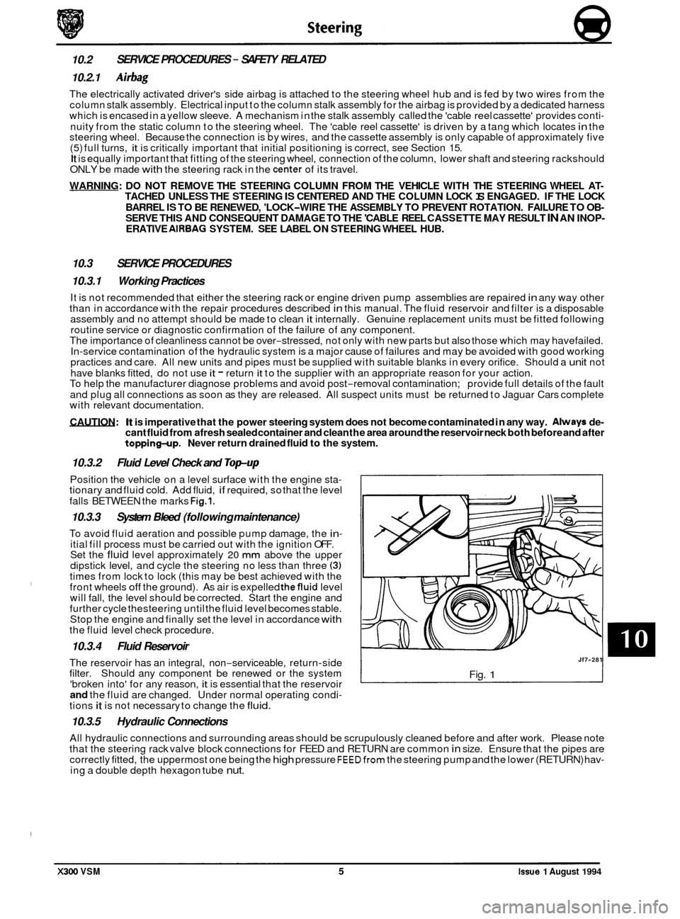
10.3.2
Position the vehicle on a level surface with the engine sta- tionary and fluid cold. Add fluid, if required, so that the level
falls BETWEEN the marks
Fig.1.
10.3.3 System Bleed (following maintenance)
To avoid fluid aeration and possible pump damage, the in- itial fill process must be carried out with the ignition OFF.
Set the fluid level approximately 20 mm above the upper
dipstick level, and cycle the steering no less than three (3) times from lock to lock (this may be best achieved with the
front wheels off the ground). As air is expelled thefluid level
will fall, the level should be corrected. Start the engine and
further cycle thesteering until the fluid level becomes stable.
Stop the engine and finally set the level in accordance
with the fluid level check procedure.
10.3.4 Fluid Reservoir
The reservoir has an integral, non-serviceable, return-side
filter. Should any component be renewed or the system
'broken into' for any reason,
it is essential that the reservoir and the fluid are changed. Under normal operating condi- tions it is not necessary to change the fluid.
10.3.5 Hydraulic Connections
Fluid
Level Check and
Top-up
Jf7-281
Fig. 1
All hydraulic connections and surrounding areas should be scrupulously cleaned before and after work. Please note
that the steering rack valve block connections for FEED and RETURN are common in size. Ensure that the pipes are
correctly fitted, the uppermost one being the high pressure FEEDfrom the steering pump and the lower (RETURN) hav- ing a double depth hexagon tube nut.
X300 VSM 5 issue 1 August 1994