clock JAGUAR XJ6 1997 2.G Workshop Manual
[x] Cancel search | Manufacturer: JAGUAR, Model Year: 1997, Model line: XJ6, Model: JAGUAR XJ6 1997 2.GPages: 227, PDF Size: 7.2 MB
Page 13 of 227
3261 Jaguar XJ6
Weekly checks0•13
Power steering
fluid level
Before you start:
4Park the vehicle on level ground.
4Set the steering wheel straight-ahead.
4The engine should be turned off.
Safety first!
lThe need for frequent topping-up indicates
a leak, which should be investigated
immediately.
For the check to be
accurate, the steering must
not be turned once the
engine has been stopped.
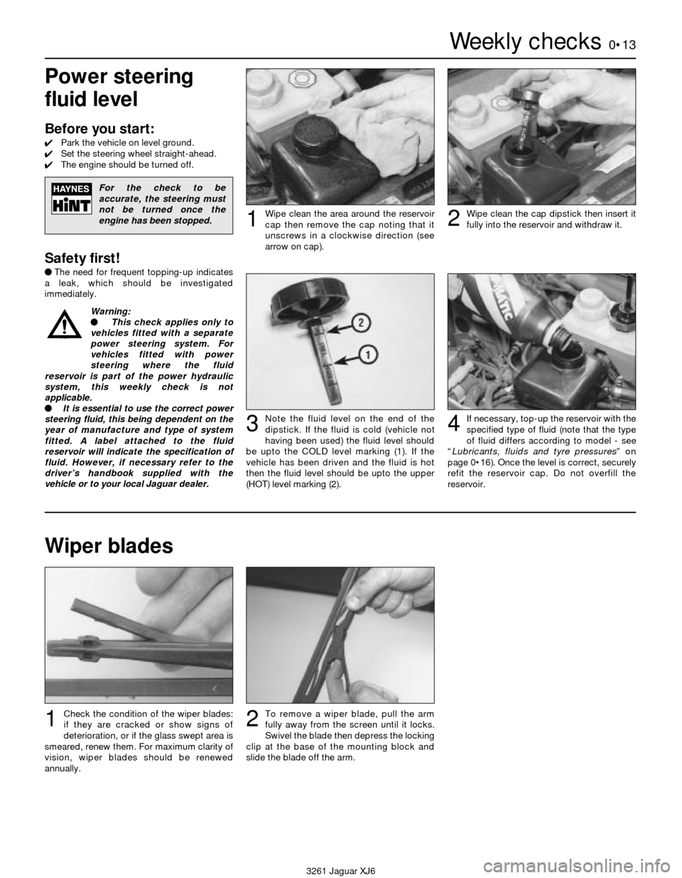
Wipe clean the area around the reservoir
cap then remove the cap noting that it
unscrews in a clockwise direction (see
arrow on cap).1Wipe clean the cap dipstick then insert it
fully into the reservoir and withdraw it.2
Note the fluid level on the end of the
dipstick. If the fluid is cold (vehicle not
having been used) the fluid level should
be upto the COLD level marking (1). If the
vehicle has been driven and the fluid is hot
then the fluid level should be upto the upper
(HOT) level marking (2).3If necessary, top-up the reservoir with the
specified type of fluid (note that the type
of fluid differs according to model - see
“Lubricants, fluids and tyre pressures” on
page 0•16). Once the level is correct, securely
refit the reservoir cap. Do not overfill the
reservoir.4
Wiper blades
Check the condition of the wiper blades:
if they are cracked or show signs of
deterioration, or if the glass swept area is
smeared, renew them. For maximum clarity of
vision, wiper blades should be renewed
annually.1To remove a wiper blade, pull the arm
fully away from the screen until it locks.
Swivel the blade then depress the locking
clip at the base of the mounting block and
slide the blade off the arm.2
Warning:
l This check applies only to
vehicles fitted with a separate
power steering system. For
vehicles fitted with power
steering where the fluid
reservoir is part of the power hydraulic
system, this weekly check is not
applicable.
l It is essential to use the correct power
steering fluid, this being dependent on the
year of manufacture and type of system
fitted. A label attached to the fluid
reservoir will indicate the specification of
fluid. However, if necessary refer to the
driver’s handbook supplied with the
vehicle or to your local Jaguar dealer.
Page 18 of 227
Lubricants and fluids
Refer to “Weekly checks”
Capacities
Engine oil
Including oil filter . . . . . . . . . . . . . . . . . . . . . . . . . . . . . . . . . . . . . . . . . . . 8.0 litres
Cooling system
All models (approximate):
From dry . . . . . . . . . . . . . . . . . . . . . . . . . . . . . . . . . . . . . . . . . . . . . . . 12.8 litres
Drain and refill . . . . . . . . . . . . . . . . . . . . . . . . . . . . . . . . . . . . . . . . . . . 9.2 litres
Transmission
Automatic transmission (approximate):
From dry:
3.2 litre model . . . . . . . . . . . . . . . . . . . . . . . . . . . . . . . . . . . . . . . . . 7.4 litres
3.6 and 4.0 litre models . . . . . . . . . . . . . . . . . . . . . . . . . . . . . . . . . 8.0 litres
Drain and refill . . . . . . . . . . . . . . . . . . . . . . . . . . . . . . . . . . . . . . . . . . . 3.0 litres
Differential
All models (approximate) . . . . . . . . . . . . . . . . . . . . . . . . . . . . . . . . . . . . 2.1 litres
Cooling system
Antifreeze mixture:
50% antifreeze . . . . . . . . . . . . . . . . . . . . . . . . . . . . . . . . . . . . . . . . . . Protection down to -37°C (5°F)
55% antifreeze . . . . . . . . . . . . . . . . . . . . . . . . . . . . . . . . . . . . . . . . . . Protection down to -45°C (-22°F)
Note:Refer to antifreeze manufacturer for latest recommendations.
Ignition system
Spark plugs:
Type:
3.2 litre model . . . . . . . . . . . . . . . . . . . . . . . . . . . . . . . . . . . . . . . . . RC12YCC
3.6 and 4.0 litre models . . . . . . . . . . . . . . . . . . . . . . . . . . . . . . . . . RC9YCC
Electrode gap . . . . . . . . . . . . . . . . . . . . . . . . . . . . . . . . . . . . . . . . . . . 0.9 mm
*The spark plug gap quoted is that recommended by Champion
for their specified plug listed above. If spark plugs of any other type
are to be fitted, refer to their manufacturer’s recommendations.
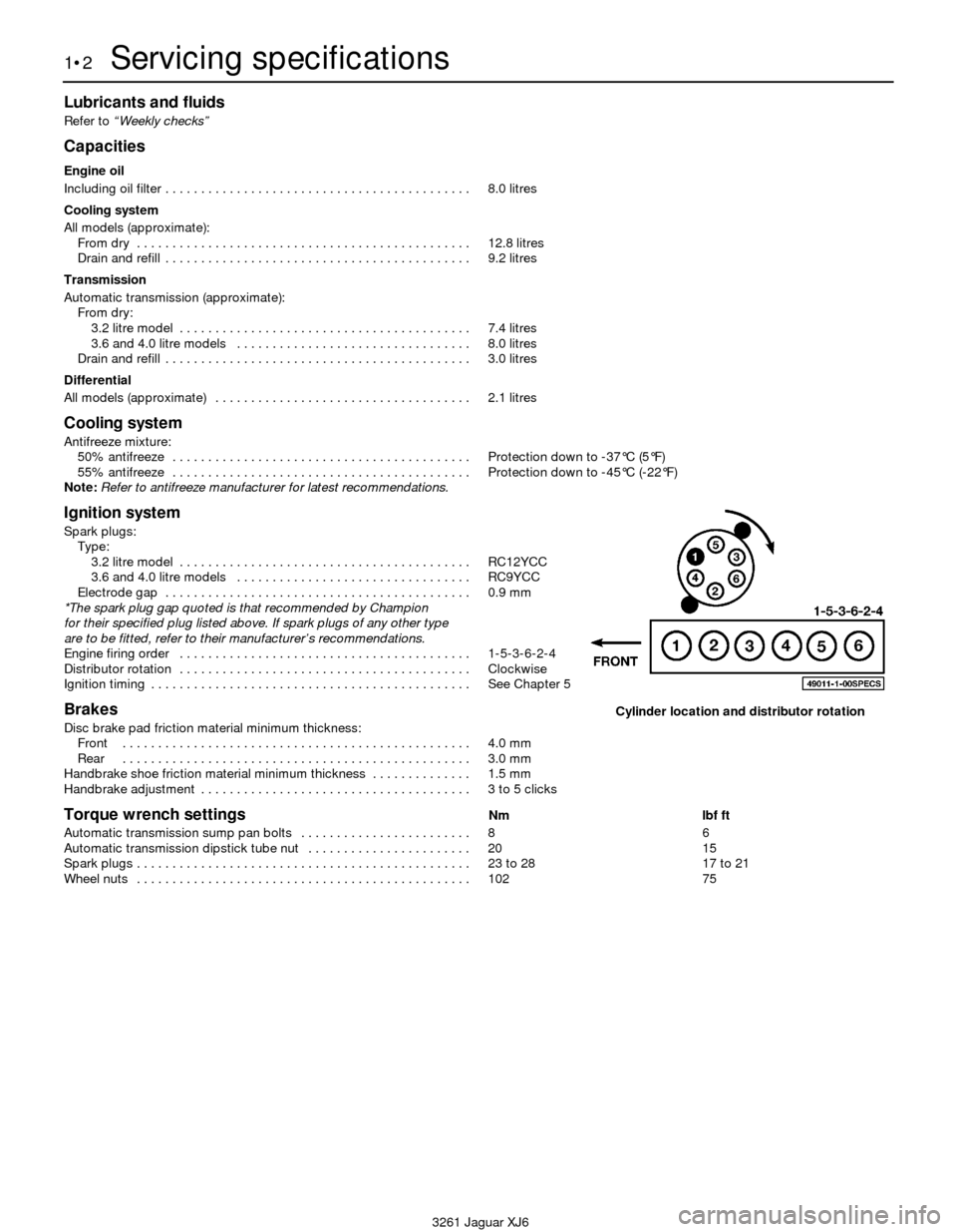
Engine firing order . . . . . . . . . . . . . . . . . . . . . . . . . . . . . . . . . . . . . . . . . 1-5-3-6-2-4
Distributor rotation . . . . . . . . . . . . . . . . . . . . . . . . . . . . . . . . . . . . . . . . . Clockwise
Ignition timing . . . . . . . . . . . . . . . . . . . . . . . . . . . . . . . . . . . . . . . . . . . . . See Chapter 5
Brakes
Disc brake pad friction material minimum thickness:
Front . . . . . . . . . . . . . . . . . . . . . . . . . . . . . . . . . . . . . . . . . . . . . . . . . 4.0 mm
Rear . . . . . . . . . . . . . . . . . . . . . . . . . . . . . . . . . . . . . . . . . . . . . . . . . 3.0 mm
Handbrake shoe friction material minimum thickness . . . . . . . . . . . . . . 1.5 mm
Handbrake adjustment . . . . . . . . . . . . . . . . . . . . . . . . . . . . . . . . . . . . . . 3 to 5 clicks
Torque wrench settingsNm lbf ft
Automatic transmission sump pan bolts . . . . . . . . . . . . . . . . . . . . . . . . 8 6
Automatic transmission dipstick tube nut . . . . . . . . . . . . . . . . . . . . . . . 20 15
Spark plugs . . . . . . . . . . . . . . . . . . . . . . . . . . . . . . . . . . . . . . . . . . . . . . . 23 to 28 17 to 21
Wheel nuts . . . . . . . . . . . . . . . . . . . . . . . . . . . . . . . . . . . . . . . . . . . . . . . 102 75
1•2Servicing specifications
3261 Jaguar XJ6
Cylinder location and distributor rotation
Page 23 of 227
exhaust components will be warm during the
actual work, so try to anticipate any potential
problems before the engine and accessories
are hot.
5Park the vehicle on a level spot. Start the
engine and allow it to reach its normal
operating temperature (the needle on the
temperature gauge should be at least above
the bottom mark). Warm oil and contaminates
will flow out more easily. Turn off the engine
when it’s warmed up. Remove the oil filler cap
located next to the valve cover.
6Raise the vehicle and support it on axle
stands.
Warning: To avoid personal
injury, never get beneath the
vehicle when it is supported by
only by a jack. The jack provided
with your vehicle is designed solely for
raising the vehicle to remove and replace
the wheels. Always use axle stands to
support the vehicle when it becomes
necessary to place your body underneath
the vehicle.
7Being careful not to touch the hot exhaust
components, place the drain pan under the
drain plug in the bottom of the pan and
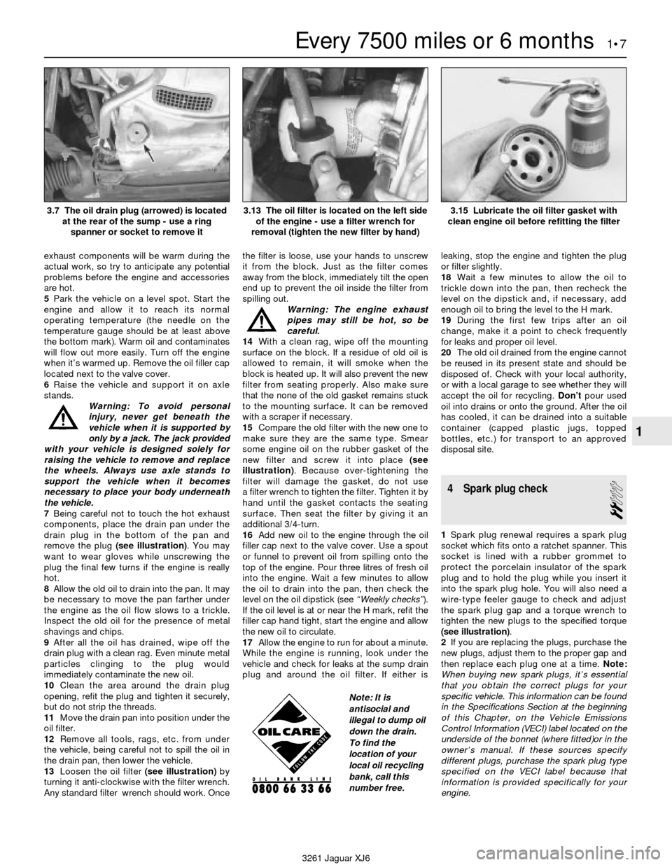
remove the plug (see illustration). You may
want to wear gloves while unscrewing the
plug the final few turns if the engine is really
hot.
8Allow the old oil to drain into the pan. It may
be necessary to move the pan farther under
the engine as the oil flow slows to a trickle.
Inspect the old oil for the presence of metal
shavings and chips.
9After all the oil has drained, wipe off the
drain plug with a clean rag. Even minute metal
particles clinging to the plug would
immediately contaminate the new oil.
10Clean the area around the drain plug
opening, refit the plug and tighten it securely,
but do not strip the threads.
11Move the drain pan into position under the
oil filter.
12Remove all tools, rags, etc. from under
the vehicle, being careful not to spill the oil in
the drain pan, then lower the vehicle.
13Loosen the oil filter (see illustration)by
turning it anti-clockwise with the filter wrench.
Any standard filter wrench should work. Oncethe filter is loose, use your hands to unscrew
it from the block. Just as the filter comes
away from the block, immediately tilt the open
end up to prevent the oil inside the filter from
spilling out.
Warning: The engine exhaust
pipes may still be hot, so be
careful.
14With a clean rag, wipe off the mounting
surface on the block. If a residue of old oil is
allowed to remain, it will smoke when the
block is heated up. It will also prevent the new
filter from seating properly. Also make sure
that the none of the old gasket remains stuck
to the mounting surface. It can be removed
with a scraper if necessary.
15Compare the old filter with the new one to
make sure they are the same type. Smear
some engine oil on the rubber gasket of the
new filter and screw it into place (see
illustration). Because over-tightening the
filter will damage the gasket, do not use
a filter wrench to tighten the filter. Tighten it by
hand until the gasket contacts the seating
surface. Then seat the filter by giving it an
additional 3/4-turn.
16Add new oil to the engine through the oil
filler cap next to the valve cover. Use a spout
or funnel to prevent oil from spilling onto the
top of the engine. Pour three litres of fresh oil
into the engine. Wait a few minutes to allow
the oil to drain into the pan, then check the
level on the oil dipstick (see “Weekly checks”).
If the oil level is at or near the H mark, refit the
filler cap hand tight, start the engine and allow
the new oil to circulate.
17Allow the engine to run for about a minute.
While the engine is running, look under the
vehicle and check for leaks at the sump drain
plug and around the oil filter. If either isleaking, stop the engine and tighten the plug
or filter slightly.
18Wait a few minutes to allow the oil to
trickle down into the pan, then recheck the
level on the dipstick and, if necessary, add
enough oil to bring the level to the H mark.
19During the first few trips after an oil
change, make it a point to check frequently
for leaks and proper oil level.
20The old oil drained from the engine cannot
be reused in its present state and should be
disposed of. Check with your local authority,
or with a local garage to see whether they will
accept the oil for recycling. Don’tpour used
oil into drains or onto the ground. After the oil
has cooled, it can be drained into a suitable
container (capped plastic jugs, topped
bottles, etc.) for transport to an approved
disposal site.
4 Spark plug check
2
1Spark plug renewal requires a spark plug
socket which fits onto a ratchet spanner. This
socket is lined with a rubber grommet to
protect the porcelain insulator of the spark
plug and to hold the plug while you insert it
into the spark plug hole. You will also need a
wire-type feeler gauge to check and adjust
the spark plug gap and a torque wrench to
tighten the new plugs to the specified torque
(see illustration).
2If you are replacing the plugs, purchase the
new plugs, adjust them to the proper gap and
then replace each plug one at a time. Note:
When buying new spark plugs, it’s essential
that you obtain the correct plugs for your
specific vehicle. This information can be found
in the Specifications Section at the beginning
of this Chapter, on the Vehicle Emissions
Control Information (VECI) label located on the
underside of the bonnet (where fitted)or in the
owner’s manual. If these sources specify
different plugs, purchase the spark plug type
specified on the VECI label because that
information is provided specifically for your
engine.
Every 7500 miles or 6 months 1•7
1
3.7 The oil drain plug (arrowed) is located
at the rear of the sump - use a ring
spanner or socket to remove it3.13 The oil filter is located on the left side
of the engine - use a filter wrench for
removal (tighten the new filter by hand)3.15 Lubricate the oil filter gasket with
clean engine oil before refitting the filter
3261 Jaguar XJ6
Note: It is
antisocial and
illegal to dump oil
down the drain.
To find the
location of your
local oil recycling
bank, call this
number free.
Page 32 of 227
20 Crankcase ventilation
system check
1
Refer to Chapter 6.
21 Drivebelt check and renewal
2
Check
1The drivebelts, or V-belts as they are
sometimes called, are located at the front of
the engine and play an important role in the
overall operation of the vehicle and its
components. Due to their function and
material make-up, the belts are prone to
failure after a period of time and should be
inspected and adjusted periodically to prevent
major engine damage.
2The number of belts used on a particular
vehicle depends on the accessories installed.
The main belt transmits power from the
crankshaft to the water pump, alternator and
the power steering pump. The second belt
transmits power from the crankshaft to the air
conditioning compressor.
3With the engine off, open the bonnet and
locate the drivebelts. With a flashlight, check
each belt for separation of the adhesive
rubber on both sides of the core, core
separation from the belt side, a severed core,
separation of the ribs from the adhesive
rubber, cracking or separation of the ribs, and
torn or worn ribs or cracks in the inner ridges
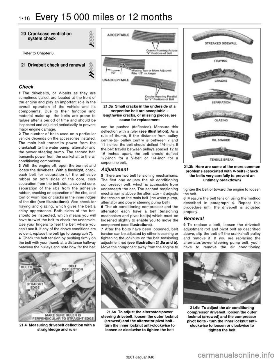
of the ribs (see illustrations). Also check for
fraying and glazing, which gives the belt a
shiny appearance. Both sides of the belt
should be inspected, which means you will
have to twist the belt to check the underside.
Use your fingers to feel the belt where you
can’t see it. If any of the above conditions are
evident, replace the belt (go to paragraph 7).
4Check the belt tension by pushing firmly on
the belt with your thumb at a distance halfway
between the pulleys and note how far the beltcan be pushed (deflected). Measure this
deflection with a ruler (see illustration). As a
rule of thumb, if the distance from pulley
centre-to- pulley centre is between 7 and
11 inches, the belt should deflect 1/4-inch. If
the belt travels between pulleys spaced 12 to
16 inches apart, the belt should deflect
1/2-inch for a V-belt or 1/4-inch for a
serpentine belt.
Adjustment
5There are two belt tensioning mechanisms.
The first one adjusts the air conditioning
compressor belt, which is accessible from
underneath the car. The second tensioning
mechanism is above the alternator - it adjusts
the tension on the main belt (the water pump,
alternator and power steering pump belt).
6The air conditioning compressor and the
alternator each have a belt tensioning
mechanism and pivot bolt(s) which must be
loosened slightly to enable you to move the
component (see illustrations).
7After the bolts have been loosened, belt
tension can be adjusted by either loosening or
tightening the locknuts on the belt tensioning
adjustment rod (see illustration 21.6a and b).
Move the component away from the engine totighten the belt or toward the engine to loosen
the belt.
8Measure the belt tension using the method
described in paragraph 4. Repeat this
procedure until the drivebelt is adjusted
properly.
Renewal
9To replace a belt, loosen the drivebelt
adjustment rod and pivot bolt as described
above, slip the belt off the crankshaft pulley
and remove it. If you are replacing the
alternator/power steering pump belt, you’ll
have to remove the air conditioning
1•16Every 15 000 miles or 12 months
21.3a Small cracks in the underside of a
serpentine belt are acceptable -
lengthwise cracks, or missing pieces, are
cause for replacement
21.3b Here are some of the more common
problems associated with V-belts (check
the belts very carefully to prevent an
untimely breakdown)
21.4 Measuring drivebelt deflection with a
straightedge and ruler
21.6a To adjust the alternator/power
steering drivebelt, loosen the outer locknut
(arrowed) and the alternator pivot bolt -
turn the inner locknut anti-clockwise to
loosen or clockwise to tighten the belt21.6b To adjust the air conditioning
compressor drivebelt, loosen the outer
locknut (arrowed) and the compressor
pivot bolts - turn the inner locknut anti-
clockwise to loosen or clockwise to
tighten the belt
3261 Jaguar XJ6
Page 36 of 227
30 Coolant renewal
2
Warning: Do not allow engine
coolant (antifreeze) to come in
contact with your skin or painted
surfaces of the vehicle. Rinse off
spills immediately with plenty of water.
Antifreeze is highly toxic if ingested. Never
leave antifreeze laying around in an open
container or in puddles on the floor;
children and pets are attracted by it’s
sweet smell and may drink it. Check with
local authorities about disposing of used
antifreeze. Your local authority may have
collection centres which will see that
antifreeze is disposed of safely.1Periodically, the cooling system should be
drained, flushed and refilled to replenish the
antifreeze mixture and prevent formation of
rust and corrosion, which can impair the
performance of the cooling system and
cause engine damage. When the cooling
system is serviced, all hoses and the radiator
cap should be checked and renewed if
necessary.
Draining
2Apply the handbrake and block the wheels.
If the vehicle has just been driven, wait several
hours to allow the engine to cool down before
beginning this procedure.
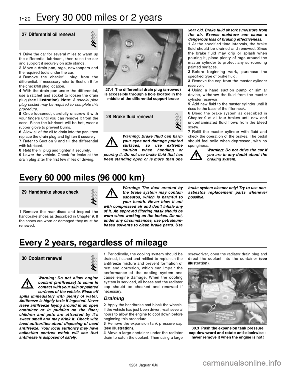
3Remove the expansion tank pressure cap
(see illustration).
4Move a large container under the radiator
drain to catch the coolant. Then using a largescrewdriver, open the radiator drain plug and
direct the coolant into the container (see
illustration).
27 Differential oil renewal
2
1Drive the car for several miles to warm up
the differential lubricant, then raise the car
and support it securely on axle stands.
2Move a drain pan, rags, newspapers and
the required tools under the car.
3Remove the check/fill plug from the
differential. If necessary refer to Section 9 for
the check/fill plug location.
4With the drain pan under the differential,
use a ratchet and socket to loosen the drain
plug (see illustration). Note:A special pipe
plug socket may be required to complete this
procedure.
5Once loosened, carefully unscrew it with
your fingers until you can remove it from the
case. Since the lubricant will be hot, wear a
rubber glove to prevent burns.
6Allow all of the oil to drain into the pan, then
replace the drain plug and tighten it securely.
7Refer to Section 9 and fill the differential
with lubricant.
8Refit the fill plug and tighten it securely.
9Lower the vehicle. Check for leaks at the
drain plug after the first few miles of driving.
28 Brake fluid renewal
2
Warning: Brake fluid can harm
your eyes and damage painted
surfaces, so use extreme
caution when handling or
pouring it. Do not use brake fluid that has
been standing open or is more than oneyear old. Brake fluid absorbs moisture from
the air. Excess moisture can cause a
dangerous loss of braking effectiveness.
1At the specified time intervals, the brake
fluid should be drained and renewed. Since
the brake fluid may drip or splash when
pouring it, place plenty of rags around the
master cylinder to protect any surrounding
painted surfaces.
2Before beginning work, purchase the
specified type of brake fluid.
3Remove the cap from the master cylinder
reservoir.
4Using a hand suction pump or similar
device, withdraw the fluid from the master
cylinder reservoir.
5Add new fluid to the master cylinder until it
rises to the base of the filler neck.
6Bleed the brake system as described in
Chapter 9 at all four brakes until new and
uncontaminated fluid flows from the bleed
screw.
7Refill the master cylinder with fluid and
check the operation of the brakes. The pedal
should feel solid when depressed, with no
sponginess.
Warning: Do not drive the car if
you are in any doubt about the
braking system.
1•20Every 30 000 miles or 2 years
27.4 The differential drain plug (arrowed)
is accessible through a hole located in the
middle of the differential support brace
30.3 Push the expansion tank pressure
cap downward and rotate anti-clockwise -
never remove it when the engine is hot!
3261 Jaguar XJ6
Every 60 000 miles (96 000 km)
29 Handbrake shoes check
2
1Remove the rear discs and inspect the
handbrake shoes as described in Chapter 9. If
the shoes are worn or damaged they must be
renewed.Warning: The dust created by
the brake system may contain
asbestos, which is harmful to
your health. Never blow it out
with compressed air and don’t inhale any
of it. An approved filtering mask should be
worn when working on the brakes. Do not,
under any circumstances, use petroleum-
based solvents to clean brake parts. Usebrake system cleaner only! Try to use non-
asbestos replacement parts whenever
possible.
Every 2 years, regardless of mileage
Page 39 of 227
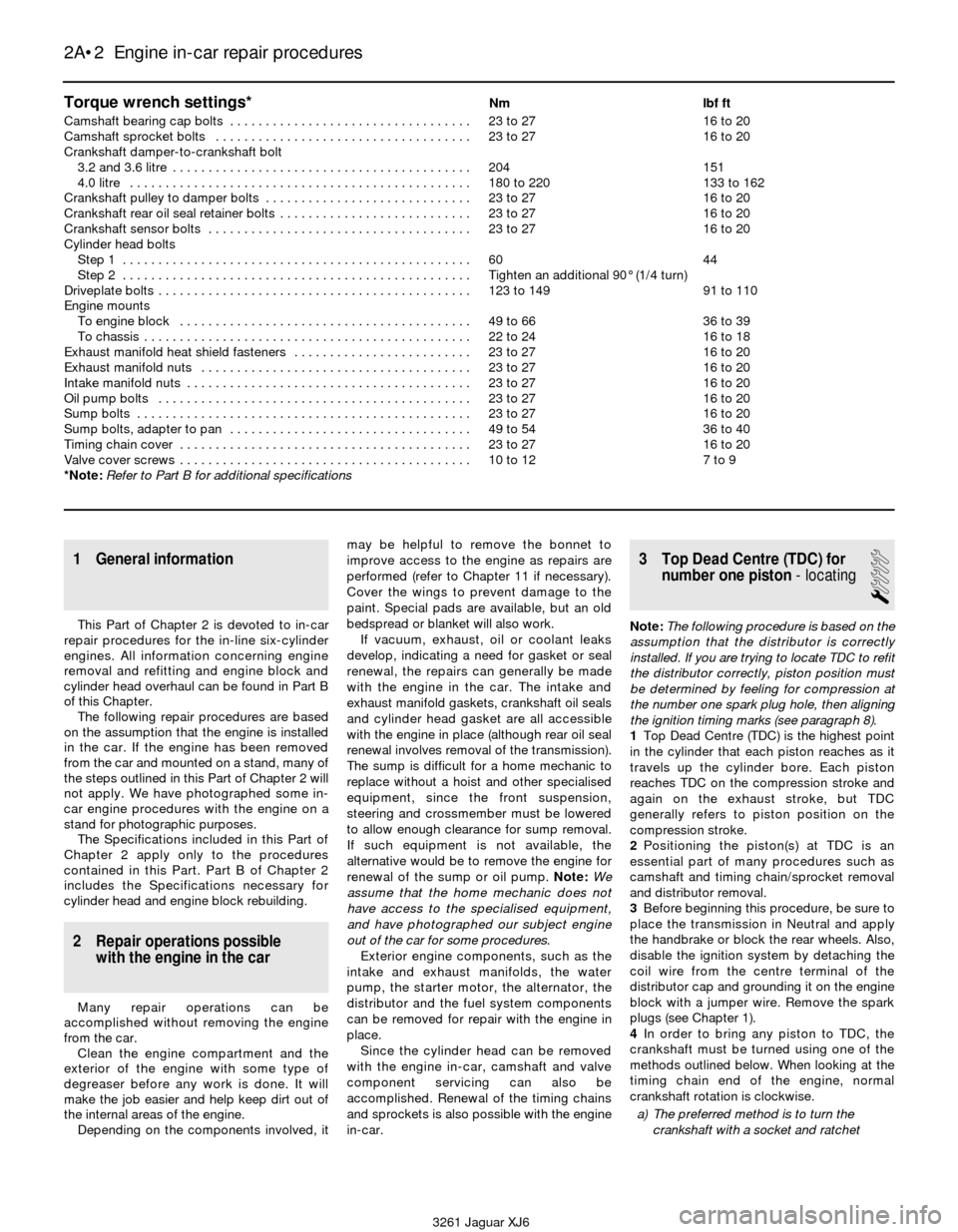
Torque wrench settings*Nm lbf ft
Camshaft bearing cap bolts . . . . . . . . . . . . . . . . . . . . . . . . . . . . . . . . . . 23 to 27 16 to 20
Camshaft sprocket bolts . . . . . . . . . . . . . . . . . . . . . . . . . . . . . . . . . . . . 23 to 27 16 to 20
Crankshaft damper-to-crankshaft bolt
3.2 and 3.6 litre . . . . . . . . . . . . . . . . . . . . . . . . . . . . . . . . . . . . . . . . . . 204 151
4.0 litre . . . . . . . . . . . . . . . . . . . . . . . . . . . . . . . . . . . . . . . . . . . . . . . . 180 to 220 133 to 162
Crankshaft pulley to damper bolts . . . . . . . . . . . . . . . . . . . . . . . . . . . . . 23 to 27 16 to 20
Crankshaft rear oil seal retainer bolts . . . . . . . . . . . . . . . . . . . . . . . . . . . 23 to 27 16 to 20
Crankshaft sensor bolts . . . . . . . . . . . . . . . . . . . . . . . . . . . . . . . . . . . . . 23 to 27 16 to 20
Cylinder head bolts
Step 1 . . . . . . . . . . . . . . . . . . . . . . . . . . . . . . . . . . . . . . . . . . . . . . . . . 60 44
Step 2 . . . . . . . . . . . . . . . . . . . . . . . . . . . . . . . . . . . . . . . . . . . . . . . . . Tighten an additional 90° (1/4 turn)
Driveplate bolts . . . . . . . . . . . . . . . . . . . . . . . . . . . . . . . . . . . . . . . . . . . . 123 to 149 91 to 110
Engine mounts
To engine block . . . . . . . . . . . . . . . . . . . . . . . . . . . . . . . . . . . . . . . . . 49 to 66 36 to 39
To chassis . . . . . . . . . . . . . . . . . . . . . . . . . . . . . . . . . . . . . . . . . . . . . . 22 to 24 16 to 18
Exhaust manifold heat shield fasteners . . . . . . . . . . . . . . . . . . . . . . . . . 23 to 27 16 to 20
Exhaust manifold nuts . . . . . . . . . . . . . . . . . . . . . . . . . . . . . . . . . . . . . . 23 to 27 16 to 20
Intake manifold nuts . . . . . . . . . . . . . . . . . . . . . . . . . . . . . . . . . . . . . . . . 23 to 27 16 to 20
Oil pump bolts . . . . . . . . . . . . . . . . . . . . . . . . . . . . . . . . . . . . . . . . . . . . 23 to 27 16 to 20
Sump bolts . . . . . . . . . . . . . . . . . . . . . . . . . . . . . . . . . . . . . . . . . . . . . . . 23 to 27 16 to 20
Sump bolts, adapter to pan . . . . . . . . . . . . . . . . . . . . . . . . . . . . . . . . . . 49 to 54 36 to 40
Timing chain cover . . . . . . . . . . . . . . . . . . . . . . . . . . . . . . . . . . . . . . . . . 23 to 27 16 to 20
Valve cover screws . . . . . . . . . . . . . . . . . . . . . . . . . . . . . . . . . . . . . . . . . 10 to 12 7 to 9
*Note:Refer to Part B for additional specifications
2A•2 Engine in-car repair procedures
3261 Jaguar XJ6
1 General information
This Part of Chapter 2 is devoted to in-car
repair procedures for the in-line six-cylinder
engines. All information concerning engine
removal and refitting and engine block and
cylinder head overhaul can be found in Part B
of this Chapter.
The following repair procedures are based
on the assumption that the engine is installed
in the car. If the engine has been removed
from the car and mounted on a stand, many of
the steps outlined in this Part of Chapter 2 will
not apply. We have photographed some in-
car engine procedures with the engine on a
stand for photographic purposes.
The Specifications included in this Part of
Chapter 2 apply only to the procedures
contained in this Part. Part B of Chapter 2
includes the Specifications necessary for
cylinder head and engine block rebuilding.
2 Repair operations possible
with the engine in the car
Many repair operations can be
accomplished without removing the engine
from the car.
Clean the engine compartment and the
exterior of the engine with some type of
degreaser before any work is done. It will
make the job easier and help keep dirt out of
the internal areas of the engine.
Depending on the components involved, itmay be helpful to remove the bonnet to
improve access to the engine as repairs are
performed (refer to Chapter 11 if necessary).
Cover the wings to prevent damage to the
paint. Special pads are available, but an old
bedspread or blanket will also work.
If vacuum, exhaust, oil or coolant leaks
develop, indicating a need for gasket or seal
renewal, the repairs can generally be made
with the engine in the car. The intake and
exhaust manifold gaskets, crankshaft oil seals
and cylinder head gasket are all accessible
with the engine in place (although rear oil seal
renewal involves removal of the transmission).
The sump is difficult for a home mechanic to
replace without a hoist and other specialised
equipment, since the front suspension,
steering and crossmember must be lowered
to allow enough clearance for sump removal.
If such equipment is not available, the
alternative would be to remove the engine for
renewal of the sump or oil pump. Note:We
assume that the home mechanic does not
have access to the specialised equipment,
and have photographed our subject engine
out of the car for some procedures.
Exterior engine components, such as the
intake and exhaust manifolds, the water
pump, the starter motor, the alternator, the
distributor and the fuel system components
can be removed for repair with the engine in
place.
Since the cylinder head can be removed
with the engine in-car, camshaft and valve
component servicing can also be
accomplished. Renewal of the timing chains
and sprockets is also possible with the engine
in-car.
3 Top Dead Centre (TDC) for
number one piston- locating
1
Note:The following procedure is based on the
assumption that the distributor is correctly
installed. If you are trying to locate TDC to refit
the distributor correctly, piston position must
be determined by feeling for compression at
the number one spark plug hole, then aligning
the ignition timing marks (see paragraph 8).
1Top Dead Centre (TDC) is the highest point
in the cylinder that each piston reaches as it
travels up the cylinder bore. Each piston
reaches TDC on the compression stroke and
again on the exhaust stroke, but TDC
generally refers to piston position on the
compression stroke.
2Positioning the piston(s) at TDC is an
essential part of many procedures such as
camshaft and timing chain/sprocket removal
and distributor removal.
3Before beginning this procedure, be sure to
place the transmission in Neutral and apply
the handbrake or block the rear wheels. Also,
disable the ignition system by detaching the
coil wire from the centre terminal of the
distributor cap and grounding it on the engine
block with a jumper wire. Remove the spark
plugs (see Chapter 1).
4In order to bring any piston to TDC, the
crankshaft must be turned using one of the
methods outlined below. When looking at the
timing chain end of the engine, normal
crankshaft rotation is clockwise.
a) The preferred method is to turn the
crankshaft with a socket and ratchet
Page 40 of 227
attached to the bolt threaded into the
front of the crankshaft. Apply pressure on
the bolt in a clockwise direction only.
Never turn the bolt anti-clockwise.
b) A remote starter switch, which may save
some time, can also be used. Follow the
instructions included with the switch.
Once the piston is close to TDC, use a
socket and ratchet as described in the
previous paragraph.
c) If an assistant is available to turn the
ignition switch to the Start position in
short bursts, you can get the piston close
to TDC without a remote starter switch.
Make sure your assistant is out of the car,
away from the ignition switch, then use a
socket and ratchet as described in
Paragraph a) to complete the procedure.
5Note the position of the terminal for the
number one spark plug lead on the distributor
cap. If the terminal isn’t marked, follow the
plug lead from the number one cylinder spark
plug to the cap.
6Use a felt-tip pen or chalk to make a mark
on the distributor body directly under the
number one terminal (see Chapter 5).
7Detach the cap from the distributor and set
it aside (see Chapter 1 if necessary).
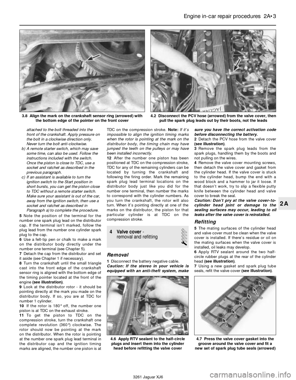
8Turn the crankshaft until the small triangle
cast into the front edge of the crankshaft
sensor ring is aligned with the bottom edge of
the timing pointer located at the front of the
engine(see illustration).
9Look at the distributor rotor - it should be
pointing directly at the mark you made on the
distributor body. If so, you are at TDC for
number 1 cylinder.
10If the rotor is 180° off, the number one
piston is at TDC on the exhaust stroke.
11To get the piston to TDC on the
compression stroke, turn the crankshaft one
complete revolution (360°) clockwise. The
rotor should now be pointing at the mark
on the distributor. When the rotor is pointing
at the number one spark plug lead terminal in
the distributor cap and the ignition timing
marks are aligned, the number one piston is atTDC on the compression stroke. Note:If it’s
impossible to align the ignition timing marks
when the rotor is pointing at the mark on the
distributor body, the timing chain may have
jumped the teeth on the pulleys or may have
been installed incorrectly.
12After the number one piston has been
positioned at TDC on the compression stroke,
TDC for any of the remaining cylinders can be
located by turning the crankshaft and
following the firing order. Mark the remaining
spark plug lead terminal locations on the
distributor body just like you did for the
number one terminal, then number the marks
to correspond with the cylinder numbers. As
you turn the crankshaft, the rotor will also
turn. When it’s pointing directly at one of the
marks on the distributor, the piston for that
particular cylinder is at TDC on the
compression stroke.
4 Valve cover-
removal and refitting
1
Removal
1Disconnect the battery negative cable.
Caution: If the stereo in your vehicle is
equipped with an anti-theft system, makesure you have the correct activation code
before disconnecting the battery.
2Detach the PCV hose from the valve cover
(see illustration).
3Remove the spark plug leads from the
spark plugs, handling them by the boots and
not pulling on the wires.
4Remove the valve cover mounting screws,
then detach the valve cover and gasket from
the cylinder head. If the valve cover is stuck
to the cylinder head, bump the end with a
wood block and a hammer to jar it loose. If
that doesn’t work, try to slip a flexible putty
knife between the cylinder head and valve
cover to break the seal.
Caution: Don’t pry at the valve cover-to-
cylinder head joint or damage to the
sealing surfaces may occur, leading to oil
leaks after the valve cover is reinstalled.
Refitting
5The mating surfaces of the cylinder head
and valve cover must be clean when the valve
cover is installed. If there’s residue or oil on
the mating surfaces when the valve cover is
installed, oil leaks may develop.
6Apply RTV sealant around the two half-
circle rubber plugs at the rear of the cylinder
head (see illustration).
7Using a new gasket and spark plug tube
seals, refit the valve cover (see illustration).
Engine in-car repair procedures 2A•3
2A
4.6 Apply RTV sealant to the half-circle
plugs and insert them into the cylinder
head before refitting the valve cover4.7 Press the valve cover gasket into the
groove around the valve cover and fit a
new set of spark plug tube seals (arrowed)
3261 Jaguar XJ6 3.8 Align the mark on the crankshaft sensor ring (arrowed) with
the bottom edge of the pointer on the front cover
4.2 Disconnect the PCV hose (arrowed) from the valve cover, then
pull the spark plug leads out by their boots, not the leads
Page 92 of 227
11Reconnect the vacuum hose to the
regulator and check the fuel pressure at idle,
comparing your reading with the value listed
in this Chapter’s Specifications. Disconnect
the vacuum hose and watch the gauge - the
pressure should jump up considerably as
soon as the hose is disconnected. If it
doesn’t, check for a vacuum signal to the fuel
pressure regulator (see Step 14).
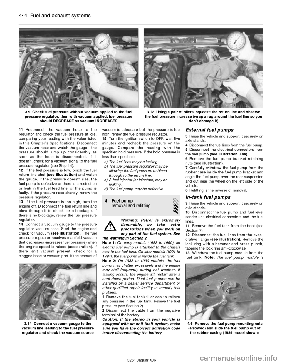
12If the fuel pressure is low, pinch the fuel
return line shut (see illustration)and watch
the gauge. If the pressure doesn’t rise, the
fuel pump is defective or there is a restriction
or leak in the fuel feed line, or the pump is
faulty. If the pressure rises sharply, renew the
pressure regulator.
13If the fuel pressure is too high, turn the
engine off. Disconnect the fuel return line and
blow through it to check for a blockage. If
there is no blockage, renew the fuel pressure
regulator.
14Connect a vacuum gauge to the pressure
regulator vacuum hose. Start the engine and
check for vacuum (see illustration). The fuel
pressure regulator receives manifold vacuum
that decreases (increases fuel pressure) when
the engine speed is raised (acceleration). If
there isn’t vacuum present, check for a
clogged hose or vacuum port. If the amount ofvacuum is adequate but the pressure is too
high, renew the fuel pressure regulator.
15Turn the ignition switch to OFF, wait five
minutes and recheck the pressure on the
gauge. Compare the reading with the
specified hold pressure. If the hold pressure is
less than specified:
a) The fuel lines may be leaking.
b) The fuel pressure regulator may be
allowing the fuel pressure to bleed
through to the return line.
c) A fuel injector (or injectors) may be
leaking.
d) The fuel pump may be defective.
4 Fuel pump-
removal and refitting
3
Warning: Petrol is extremely
flammable, so take extra
precautions when you work on
any part of the fuel system. See
the Warning in Section 2.
Note 1:On early models (1988 to 1990), an
electric fuel pump is attached to the chassis
next to the fuel tank. On later models (1991 to
1994), the fuel pump is inside the fuel tank.
Note 2: On 1988 to 1990 models, the fuel
pump may chatter excessively and the engine
may stall frequently during hot weather. If
stalling occurs, the engine will restart after a
cool-down period. Dual fuel pumps can be
installed by a dealer service department or
other qualified repair facility to remedy this
problem.
1Remove the fuel tank filler cap to relieve
any pressure in the fuel tank. Relieve the fuel
pressure (see Section 2).
2Disconnect the cable from the negative
terminal of the battery.
Caution: If the stereo in your vehicle is
equipped with an anti-theft system, make
sure you have the correct activation code
before disconnecting the battery.
External fuel pumps
3Raise the vehicle and support it securely on
axle stands.
4Disconnect the fuel lines from the fuel pump.
5Disconnect the electrical connectors from
the fuel pump (see illustration 3.4a).
6Remove the fuel pump bracket retaining
nuts (see illustration).
7Carefully withdraw the fuel pump from the
rubber case inside the fuel pump bracket and
angle the fuel pump over the rear suspension
and out near the wheel on the left side of the
vehicle.
8Refitting is the reverse of removal.
In-tank fuel pumps
9Raise the vehicle and support it securely on
axle stands.
10Disconnect the fuel pump and fuel level
sender unit electrical connectors and the fuel
lines.
11Remove the fuel tank from the boot (see
Section 7).
12Disconnect the fuel lines from the evap-
orative flange (see illustration). Remove the
lock ring with a hammer and brass punch,
tapping the lock ring anti-clockwise.
13Withdraw the fuel pump module from the
fuel tank. Note: The fuel pump module is
4•4 Fuel and exhaust systems
3.14 Connect a vacuum gauge to the
vacuum line leading to the fuel pressure
regulator and check the vacuum source4.6 Remove the fuel pump mounting nuts
(arrowed) and slide the fuel pump out of
the rubber casing (1989 model shown)
3261 Jaguar XJ6 3.9 Check fuel pressure without vacuum applied to the fuel
pressure regulator, then with vacuum applied; fuel pressure
should DECREASE as vacuum INCREASES
3.12 Using a pair of pliers, squeeze the return line and observe
the fuel pressure increase (wrap a rag around the fuel line so you
don’t damage it)
Page 94 of 227
tank. If there is any doubt about the
amount of fuel in the tank, drain the fuel
tank completely before attempting this
procedure (Section 7, paragraph 1).
9Disconnect the cable from the negative
terminal of the battery. Disconnect the fuel level
sender unit/fuel pump electrical connector.
Caution: If the stereo in your vehicle is
equipped with an anti-theft system, make
sure you have the correct activation code
before disconnecting the battery.
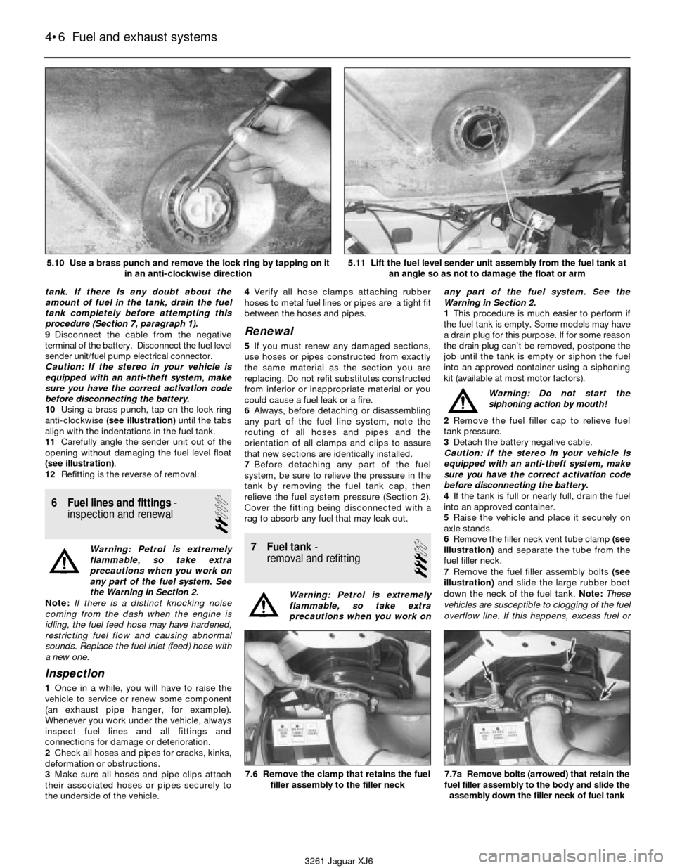
10Using a brass punch, tap on the lock ring
anti-clockwise (see illustration)until the tabs
align with the indentations in the fuel tank.
11Carefully angle the sender unit out of the
opening without damaging the fuel level float
(see illustration).
12Refitting is the reverse of removal.
6 Fuel lines and fittings-
inspection and renewal
2
Warning: Petrol is extremely
flammable, so take extra
precautions when you work on
any part of the fuel system. See
the Warning in Section 2.
Note:If there is a distinct knocking noise
coming from the dash when the engine is
idling, the fuel feed hose may have hardened,
restricting fuel flow and causing abnormal
sounds. Replace the fuel inlet (feed) hose with
a new one.
Inspection
1Once in a while, you will have to raise the
vehicle to service or renew some component
(an exhaust pipe hanger, for example).
Whenever you work under the vehicle, always
inspect fuel lines and all fittings and
connections for damage or deterioration.
2Check all hoses and pipes for cracks, kinks,
deformation or obstructions.
3Make sure all hoses and pipe clips attach
their associated hoses or pipes securely to
the underside of the vehicle.4Verify all hose clamps attaching rubber
hoses to metal fuel lines or pipes are a tight fit
between the hoses and pipes.
Renewal
5If you must renew any damaged sections,
use hoses or pipes constructed from exactly
the same material as the section you are
replacing. Do not refit substitutes constructed
from inferior or inappropriate material or you
could cause a fuel leak or a fire.
6Always, before detaching or disassembling
any part of the fuel line system, note the
routing of all hoses and pipes and the
orientation of all clamps and clips to assure
that new sections are identically installed.
7Before detaching any part of the fuel
system, be sure to relieve the pressure in the
tank by removing the fuel tank cap, then
relieve the fuel system pressure (Section 2).
Cover the fitting being disconnected with a
rag to absorb any fuel that may leak out.
7 Fuel tank-
removal and refitting
3
Warning: Petrol is extremely
flammable, so take extra
precautions when you work onany part of the fuel system. See the
Warning in Section 2.
1This procedure is much easier to perform if
the fuel tank is empty. Some models may have
a drain plug for this purpose. If for some reason
the drain plug can’t be removed, postpone the
job until the tank is empty or siphon the fuel
into an approved container using a siphoning
kit (available at most motor factors).
Warning: Do not start the
siphoning action by mouth!
2Remove the fuel filler cap to relieve fuel
tank pressure.
3Detach the battery negative cable.
Caution: If the stereo in your vehicle is
equipped with an anti-theft system, make
sure you have the correct activation code
before disconnecting the battery.
4If the tank is full or nearly full, drain the fuel
into an approved container.
5Raise the vehicle and place it securely on
axle stands.
6Remove the filler neck vent tube clamp (see
illustration)and separate the tube from the
fuel filler neck.
7Remove the fuel filler assembly bolts (see
illustration)and slide the large rubber boot
down the neck of the fuel tank. Note:These
vehicles are susceptible to clogging of the fuel
overflow line. If this happens, excess fuel or
4•6 Fuel and exhaust systems
7.6 Remove the clamp that retains the fuel
filler assembly to the filler neck7.7a Remove bolts (arrowed) that retain the
fuel filler assembly to the body and slide the
assembly down the filler neck of fuel tank
3261 Jaguar XJ6 5.10 Use a brass punch and remove the lock ring by tapping on it
in an anti-clockwise direction
5.11 Lift the fuel level sender unit assembly from the fuel tank at
an angle so as not to damage the float or arm
Page 113 of 227
2The CHECK ENGINE warning light, which is
located on the instrument panel, comes on
when the ignition switch is turned to ON and
the engine is not running. When the engine is
started, the warning light should go out. If the
light remains on, the self-diagnosis system
has detected a malfunction. Note: The
CHECK ENGINE light on early models is
displayed on the dashboard VCM panel on the
right side. Later models are equipped with a
separate CHECK ENGINE light on the left side
of the instrument cluster.Note:Not all the
codes will cause the CHECK ENGINE light to
activate. When performing any fuel or
emissions systems diagnosis, always check
for codes that may be stored but not indicated
by the CHECK ENGINE light.
Obtaining fault code output
3To obtain an output of diagnostic codes,
verify first that the battery voltage is above 11
volts, the throttle is fully closed, the
transmission is in Park, the accessory
switches are off and the engine is at normal
operating temperature.
4Turn the ignition switch to ON but don’t
start the engine (Position II). Note:On 1988
and 1989 models, remember to turn the
ignition switch to position II without turning
the key to OFF.
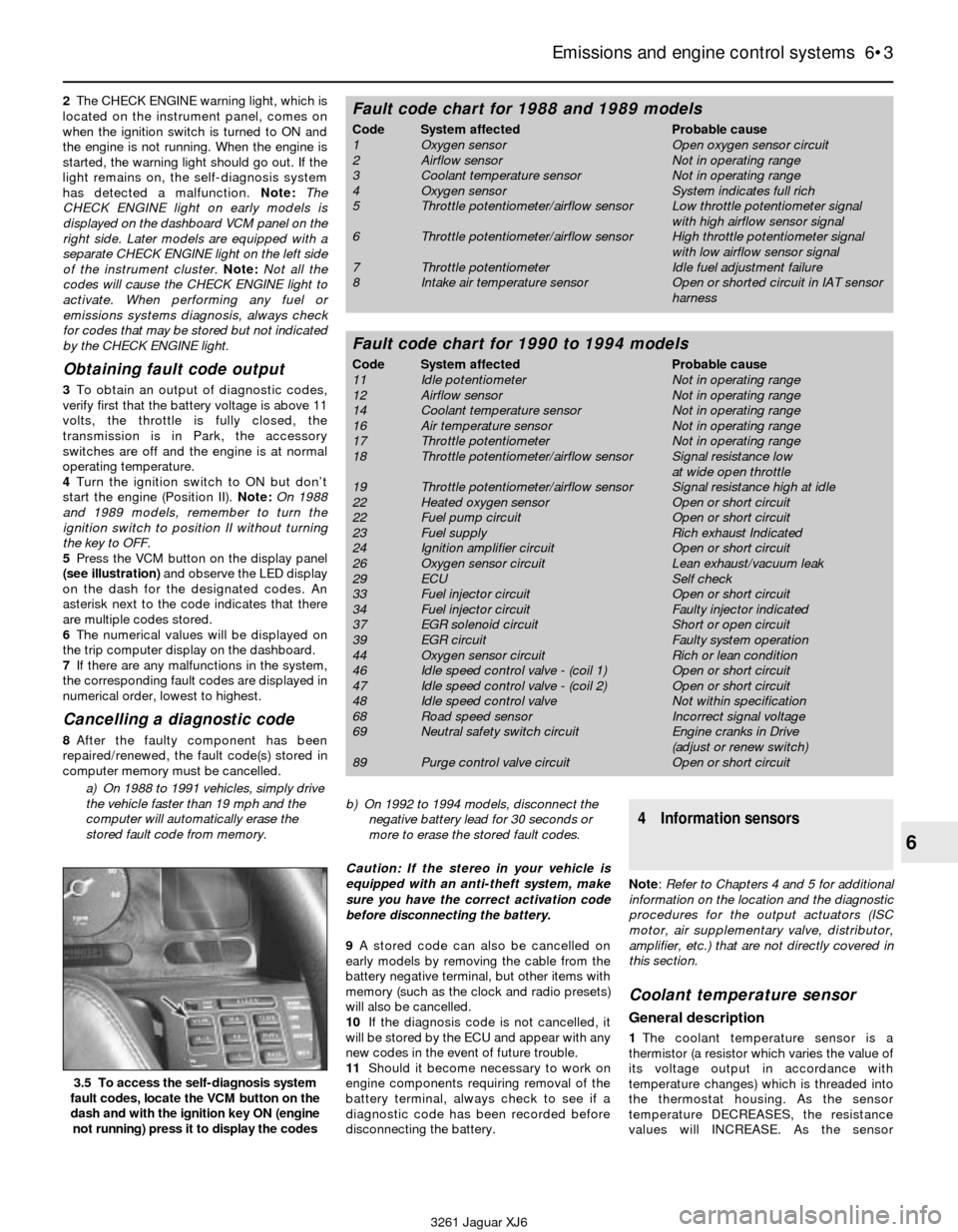
5Press the VCM button on the display panel
(see illustration)and observe the LED display
on the dash for the designated codes. An
asterisk next to the code indicates that there
are multiple codes stored.
6The numerical values will be displayed on
the trip computer display on the dashboard.
7If there are any malfunctions in the system,
the corresponding fault codes are displayed in
numerical order, lowest to highest.
Cancelling a diagnostic code
8After the faulty component has been
repaired/renewed, the fault code(s) stored in
computer memory must be cancelled.
a) On 1988 to 1991 vehicles, simply drive
the vehicle faster than 19 mph and the
computer will automatically erase the
stored fault code from memory.b) On 1992 to 1994 models, disconnect the
negative battery lead for 30 seconds or
more to erase the stored fault codes.
Caution: If the stereo in your vehicle is
equipped with an anti-theft system, make
sure you have the correct activation code
before disconnecting the battery.
9A stored code can also be cancelled on
early models by removing the cable from the
battery negative terminal, but other items with
memory (such as the clock and radio presets)
will also be cancelled.
10If the diagnosis code is not cancelled, it
will be stored by the ECU and appear with any
new codes in the event of future trouble.
11Should it become necessary to work on
engine components requiring removal of the
battery terminal, always check to see if a
diagnostic code has been recorded before
disconnecting the battery.
4 Information sensors
Note: Refer to Chapters 4 and 5 for additional
information on the location and the diagnostic
procedures for the output actuators (ISC
motor, air supplementary valve, distributor,
amplifier, etc.) that are not directly covered in
this section.
Coolant temperature sensor
General description
1The coolant temperature sensor is a
thermistor (a resistor which varies the value of
its voltage output in accordance with
temperature changes) which is threaded into
the thermostat housing. As the sensor
temperature DECREASES, the resistance
values will INCREASE. As the sensor
Emissions and engine control systems 6•3
6
3.5 To access the self-diagnosis system
fault codes, locate the VCM button on the
dash and with the ignition key ON (engine
not running) press it to display the codes
3261 Jaguar XJ6
Fault code chart for 1988 and 1989 models
Code System affected Probable cause
1 Oxygen sensor Open oxygen sensor circuit
2 Airflow sensor Not in operating range
3 Coolant temperature sensor Not in operating range
4 Oxygen sensor System indicates full rich
5 Throttle potentiometer/airflow sensor Low throttle potentiometer signal
with high airflow sensor signal
6 Throttle potentiometer/airflow sensor High throttle potentiometer signal
with low airflow sensor signal
7 Throttle potentiometer Idle fuel adjustment failure
8 Intake air temperature sensor Open or shorted circuit in IAT sensor
harness
Fault code chart for 1990 to 1994 models
Code System affected Probable cause
11 Idle potentiometer Not in operating range
12 Airflow sensor Not in operating range
14 Coolant temperature sensor Not in operating range
16 Air temperature sensor Not in operating range
17 Throttle potentiometer Not in operating range
18 Throttle potentiometer/airflow sensor Signal resistance low
at wide open throttle
19 Throttle potentiometer/airflow sensor Signal resistance high at idle
22 Heated oxygen sensor Open or short circuit
22 Fuel pump circuit Open or short circuit
23 Fuel supply Rich exhaust Indicated
24 Ignition amplifier circuit Open or short circuit
26 Oxygen sensor circuit Lean exhaust/vacuum leak
29 ECU Self check
33 Fuel injector circuit Open or short circuit
34 Fuel injector circuit Faulty injector indicated
37 EGR solenoid circuit Short or open circuit
39 EGR circuit Faulty system operation
44 Oxygen sensor circuit Rich or lean condition
46 Idle speed control valve - (coil 1) Open or short circuit
47 Idle speed control valve - (coil 2) Open or short circuit
48 Idle speed control valve Not within specification
68 Road speed sensor Incorrect signal voltage
69 Neutral safety switch circuit Engine cranks in Drive
(adjust or renew switch)
89 Purge control valve circuit Open or short circuit