JEEP CHEROKEE 1995 Service Repair Manual
Manufacturer: JEEP, Model Year: 1995, Model line: CHEROKEE, Model: JEEP CHEROKEE 1995Pages: 2198, PDF Size: 82.83 MB
Page 1181 of 2198
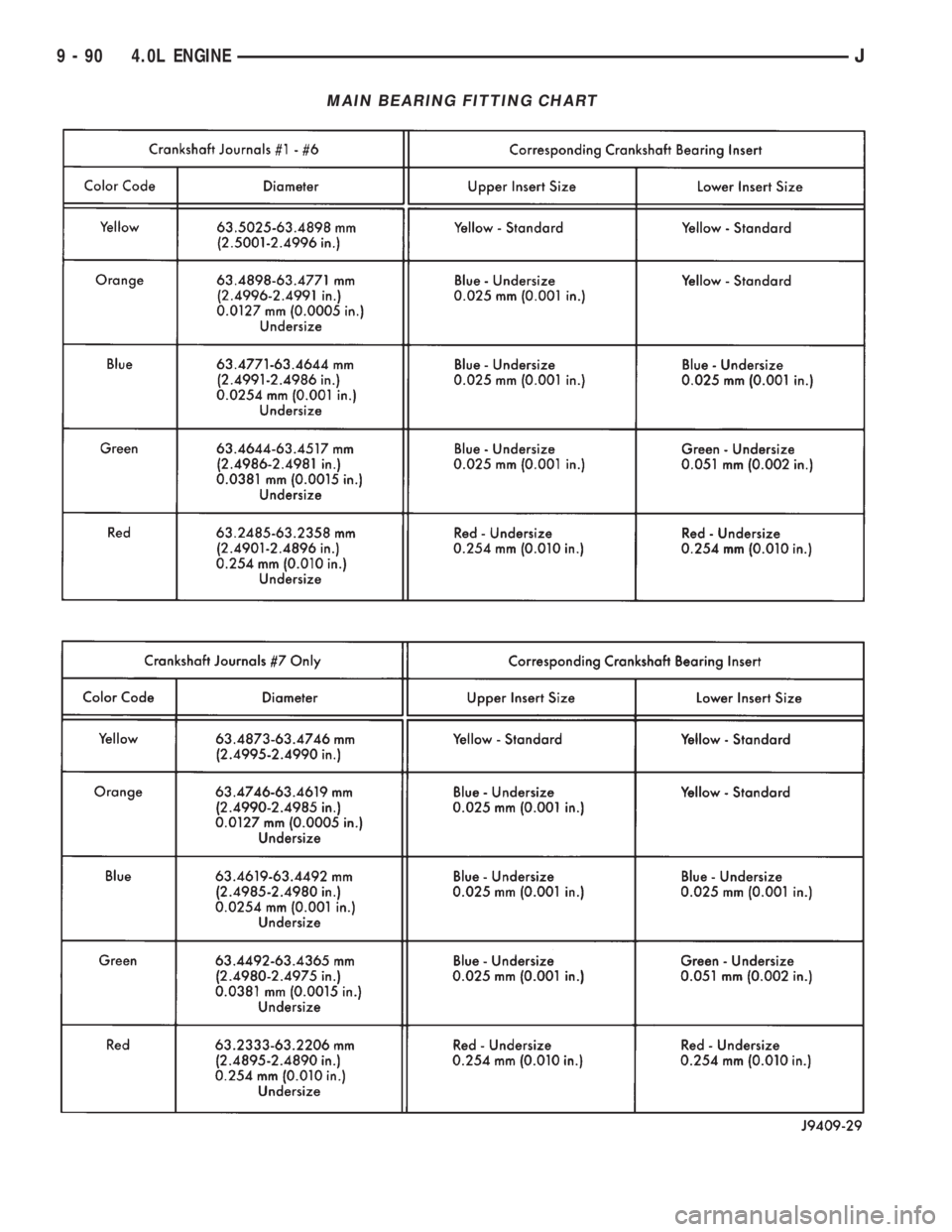
MAIN BEARING FITTING CHART
9 - 90 4.0L ENGINEJ
Page 1182 of 2198
REMOVAL
(1) Remove the engine flywheel or converter drive
plate.
(2) Remove the oil pan.
(3) Remove the rear main bearing cap (No.7).
(4) Push the upper seal out of the groove. Ensure
that the crankshaft and seal groove are not damaged.
(5) Remove the lower half of the seal from the
bearing cap.
INSTALLATION
(1) Wipe the seal surface area of the crankshaft
until it is clean.
(2) Apply a thin coat of engine oil.
(3) Coat the lip of the seal with engine oil.
(4) Carefully position the upper seal into the
groove in the cylinder block. The lip of the seal faces
toward the front of the engine.
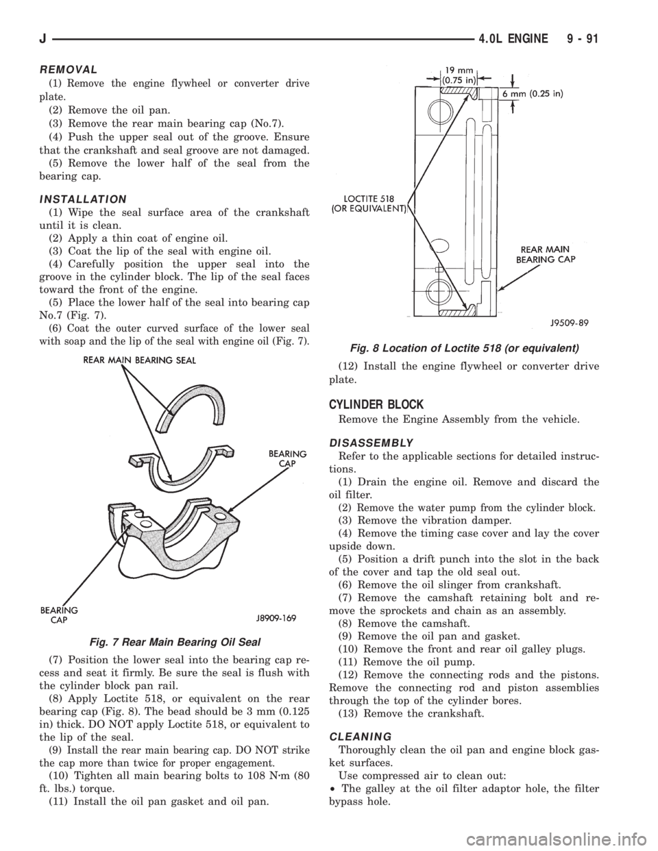
(5) Place the lower half of the seal into bearing cap
No.7 (Fig. 7).
(6) Coat the outer curved surface of the lower seal
with soap and the lip of the seal with engine oil (Fig. 7).
(7) Position the lower seal into the bearing cap re-
cess and seat it firmly. Be sure the seal is flush with
the cylinder block pan rail.
(8) Apply Loctite 518, or equivalent on the rear
bearing cap (Fig. 8). The bead should be 3 mm (0.125
in) thick. DO NOT apply Loctite 518, or equivalent to
the lip of the seal.
(9) Install the rear main bearing cap. DO NOT strike
the cap more than twice for proper engagement.
(10) Tighten all main bearing bolts to 108 Nzm (80
ft. lbs.) torque.
(11) Install the oil pan gasket and oil pan.(12) Install the engine flywheel or converter drive
plate.
CYLINDER BLOCK
Remove the Engine Assembly from the vehicle.
DISASSEMBLY
Refer to the applicable sections for detailed instruc-
tions.
(1) Drain the engine oil. Remove and discard the
oil filter.
(2) Remove the water pump from the cylinder block.
(3) Remove the vibration damper.
(4) Remove the timing case cover and lay the cover
upside down.
(5) Position a drift punch into the slot in the back
of the cover and tap the old seal out.
(6) Remove the oil slinger from crankshaft.
(7) Remove the camshaft retaining bolt and re-
move the sprockets and chain as an assembly.
(8) Remove the camshaft.
(9) Remove the oil pan and gasket.
(10) Remove the front and rear oil galley plugs.
(11) Remove the oil pump.
(12) Remove the connecting rods and the pistons.
Remove the connecting rod and piston assemblies
through the top of the cylinder bores.
(13) Remove the crankshaft.
CLEANING
Thoroughly clean the oil pan and engine block gas-
ket surfaces.
Use compressed air to clean out:
²The galley at the oil filter adaptor hole, the filter
bypass hole.
Fig. 7 Rear Main Bearing Oil Seal
Fig. 8 Location of Loctite 518 (or equivalent)
J4.0L ENGINE 9 - 91
Page 1183 of 2198
²The front and rear oil galley holes.
²The feed holes for the crankshaft main bearings.
Once the block has been completely cleaned, apply
Loctite PST pipe sealant with Teflon 592 to the
threads of the front and rear oil galley plugs. Tighten
the plugs to 41 Nzm (30 ft. lbs.) torque.
INSPECTIONÐCYLINDER BORE
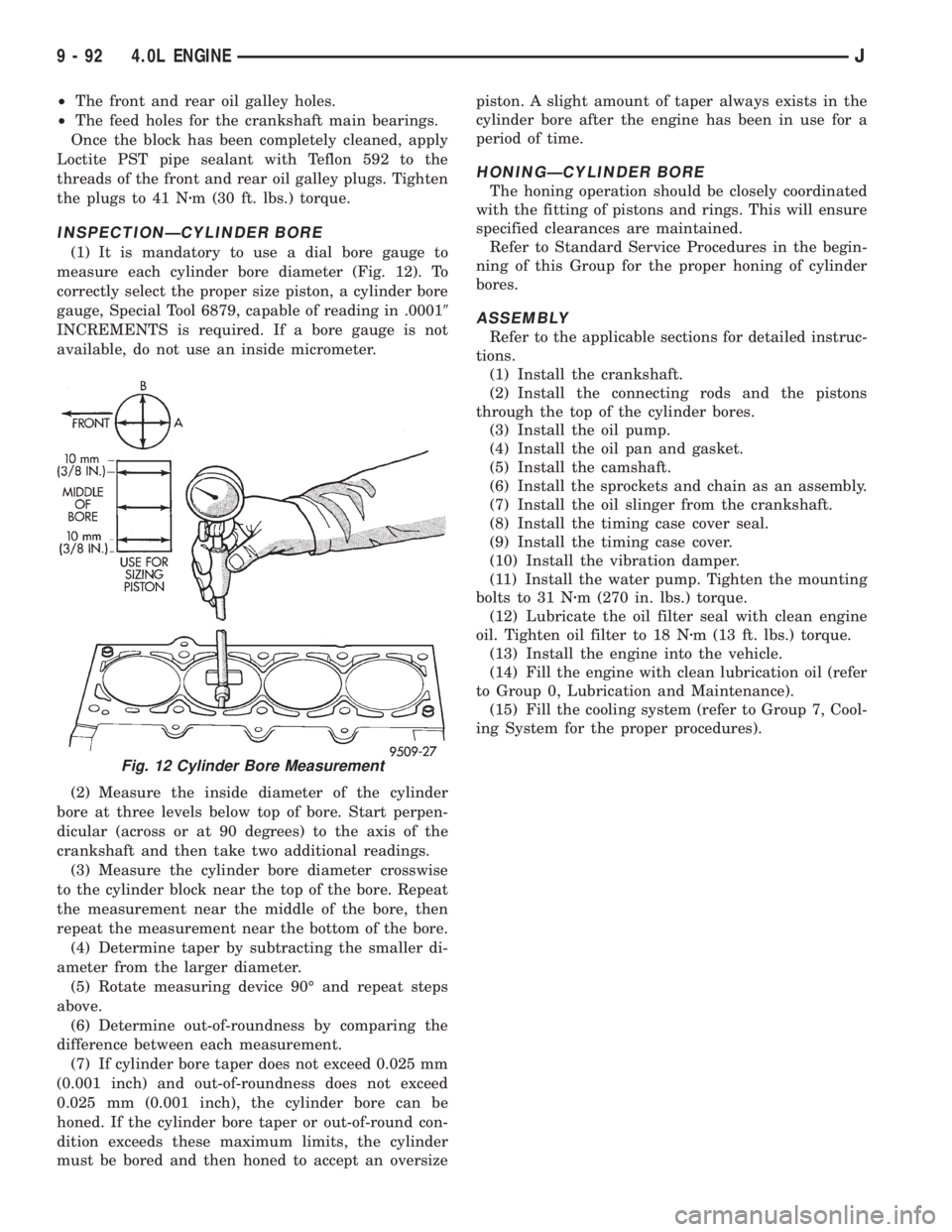
(1) It is mandatory to use a dial bore gauge to
measure each cylinder bore diameter (Fig. 12). To
correctly select the proper size piston, a cylinder bore
gauge, Special Tool 6879, capable of reading in .00019
INCREMENTS is required. If a bore gauge is not
available, do not use an inside micrometer.
(2) Measure the inside diameter of the cylinder
bore at three levels below top of bore. Start perpen-
dicular (across or at 90 degrees) to the axis of the
crankshaft and then take two additional readings.
(3) Measure the cylinder bore diameter crosswise
to the cylinder block near the top of the bore. Repeat
the measurement near the middle of the bore, then
repeat the measurement near the bottom of the bore.
(4) Determine taper by subtracting the smaller di-
ameter from the larger diameter.
(5) Rotate measuring device 90É and repeat steps
above.
(6) Determine out-of-roundness by comparing the
difference between each measurement.
(7) If cylinder bore taper does not exceed 0.025 mm
(0.001 inch) and out-of-roundness does not exceed
0.025 mm (0.001 inch), the cylinder bore can be
honed. If the cylinder bore taper or out-of-round con-
dition exceeds these maximum limits, the cylinder
must be bored and then honed to accept an oversizepiston. A slight amount of taper always exists in the
cylinder bore after the engine has been in use for a
period of time.
HONINGÐCYLINDER BORE
The honing operation should be closely coordinated
with the fitting of pistons and rings. This will ensure
specified clearances are maintained.
Refer to Standard Service Procedures in the begin-
ning of this Group for the proper honing of cylinder
bores.
ASSEMBLY
Refer to the applicable sections for detailed instruc-
tions.
(1) Install the crankshaft.
(2) Install the connecting rods and the pistons
through the top of the cylinder bores.
(3) Install the oil pump.
(4) Install the oil pan and gasket.
(5) Install the camshaft.
(6) Install the sprockets and chain as an assembly.
(7) Install the oil slinger from the crankshaft.
(8) Install the timing case cover seal.
(9) Install the timing case cover.
(10) Install the vibration damper.
(11) Install the water pump. Tighten the mounting
bolts to 31 Nzm (270 in. lbs.) torque.
(12) Lubricate the oil filter seal with clean engine
oil. Tighten oil filter to 18 Nzm (13 ft. lbs.) torque.
(13) Install the engine into the vehicle.
(14) Fill the engine with clean lubrication oil (refer
to Group 0, Lubrication and Maintenance).
(15) Fill the cooling system (refer to Group 7, Cool-
ing System for the proper procedures).
Fig. 12 Cylinder Bore Measurement
9 - 92 4.0L ENGINEJ
Page 1184 of 2198
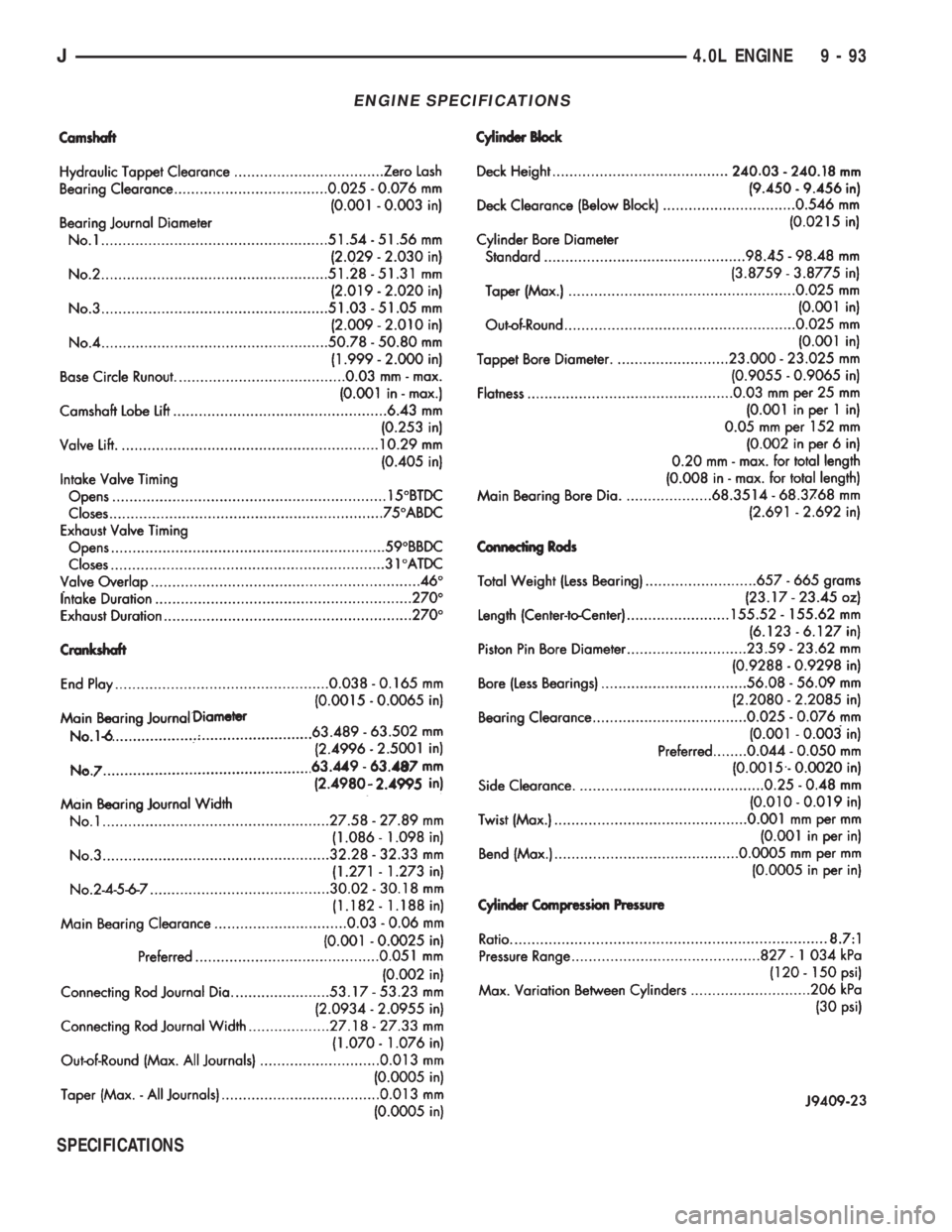
SPECIFICATIONS
ENGINE SPECIFICATIONS
J4.0L ENGINE 9 - 93
Page 1185 of 2198
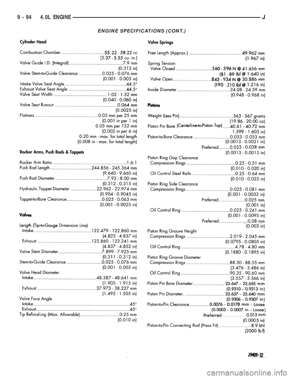
ENGINE SPECIFICATIONS (CONT.)
9 - 94 4.0L ENGINEJ
Page 1186 of 2198
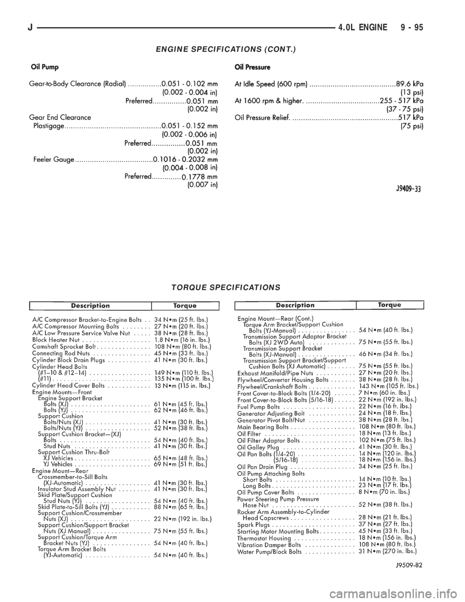
ENGINE SPECIFICATIONS (CONT.)
TORQUE SPECIFICATIONS
J4.0L ENGINE 9 - 95
Page 1187 of 2198

Page 1188 of 2198
EXHAUST SYSTEM AND INTAKE MANIFOLD
CONTENTS
page page
EXHAUST SYSTEM....................... 1
EXHAUST SYSTEM DIAGNOSIS............. 2SERVICE PROCEDURES................... 3
TORQUE SPECIFICATIONS................ 10
EXHAUST SYSTEM
GENERAL INFORMATION
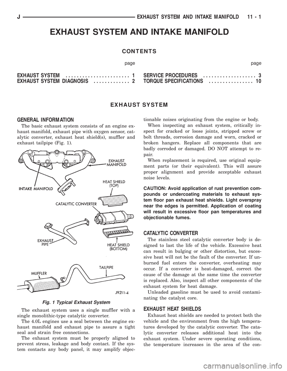
The basic exhaust system consists of an engine ex-
haust manifold, exhaust pipe with oxygen sensor, cat-
alytic converter, exhaust heat shield(s), muffler and
exhaust tailpipe (Fig. 1).
The exhaust system uses a single muffler with a
single monolithic-type catalytic converter.
The 4.0L engines use a seal between the engine ex-
haust manifold and exhaust pipe to assure a tight
seal and strain free connections.
The exhaust system must be properly aligned to
prevent stress, leakage and body contact. If the sys-
tem contacts any body panel, it may amplify objec-tionable noises originating from the engine or body.
When inspecting an exhaust system, critically in-
spect for cracked or loose joints, stripped screw or
bolt threads, corrosion damage and worn, cracked or
broken hangers. Replace all components that are
badly corroded or damaged. DO NOT attempt to re-
pair.
When replacement is required, use original equip-
ment parts (or their equivalent). This will assure
proper alignment and provide acceptable exhaust
noise levels.
CAUTION: Avoid application of rust prevention com-
pounds or undercoating materials to exhaust sys-
tem floor pan exhaust heat shields. Light overspray
near the edges is permitted. Application of coating
will result in excessive floor pan temperatures and
objectionable fumes.
CATALYTIC CONVERTER
The stainless steel catalytic converter body is de-
signed to last the life of the vehicle. Excessive heat
can result in bulging or other distortion, but exces-
sive heat will not be the fault of the converter. If un-
burned fuel enters the converter, overheating may
occur. If a converter is heat-damaged, correct the
cause of the damage at the same time the converter
is replaced. Also, inspect all other components of the
exhaust system for heat damage.
Unleaded gasoline must be used to avoid contami-
nating the catalyst core.
EXHAUST HEAT SHIELDS
Exhaust heat shields are needed to protect both the
vehicle and the environment from the high tempera-
tures developed by the catalytic converter. The cata-
lytic converter releases additional heat into the
exhaust system. Under severe operating conditions,
the temperature increases in the area of the con-
Fig. 1 Typical Exhaust System
JEXHAUST SYSTEM AND INTAKE MANIFOLD 11 - 1
Page 1189 of 2198
verter. Such conditions can exist when the engine
misfires or otherwise does not operate at peak effi-
ciency.
DO NOT remove spark plug wires from plugs or by
any other means short out cylinders. Failure of the
catalytic converter can occur due to a temperature
increase caused by unburned fuel passing through
the converter.DO NOT allow the engine to operate at fast idle for
extended periods (over 5 minutes). This condition
may result in excessive temperatures in the exhaust
system and on the floor pan.
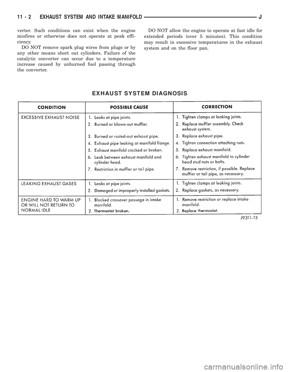
EXHAUST SYSTEM DIAGNOSIS
11 - 2 EXHAUST SYSTEM AND INTAKE MANIFOLDJ
Page 1190 of 2198
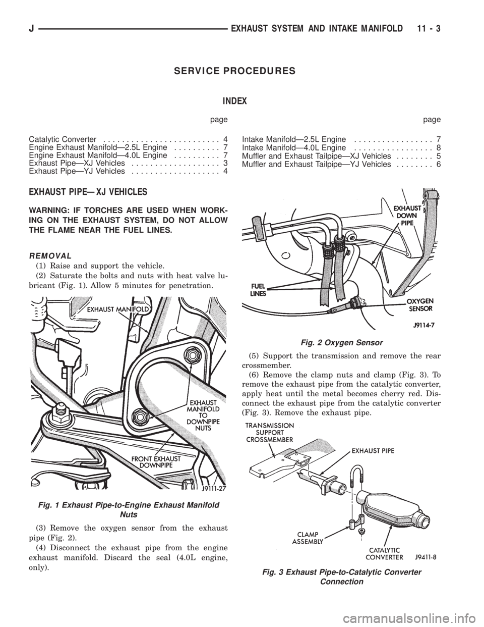
SERVICE PROCEDURES
INDEX
page page
Catalytic Converter......................... 4
Engine Exhaust ManifoldÐ2.5L Engine.......... 7
Engine Exhaust ManifoldÐ4.0L Engine.......... 7
Exhaust PipeÐXJ Vehicles................... 3
Exhaust PipeÐYJ Vehicles................... 4Intake ManifoldÐ2.5L Engine................. 7
Intake ManifoldÐ4.0L Engine................. 8
Muffler and Exhaust TailpipeÐXJ Vehicles........ 5
Muffler and Exhaust TailpipeÐYJ Vehicles........ 6
EXHAUST PIPEÐXJ VEHICLES
WARNING: IF TORCHES ARE USED WHEN WORK-
ING ON THE EXHAUST SYSTEM, DO NOT ALLOW
THE FLAME NEAR THE FUEL LINES.
REMOVAL
(1) Raise and support the vehicle.
(2) Saturate the bolts and nuts with heat valve lu-
bricant (Fig. 1). Allow 5 minutes for penetration.
(3) Remove the oxygen sensor from the exhaust
pipe (Fig. 2).
(4) Disconnect the exhaust pipe from the engine
exhaust manifold. Discard the seal (4.0L engine,
only).(5) Support the transmission and remove the rear
crossmember.
(6) Remove the clamp nuts and clamp (Fig. 3). To
remove the exhaust pipe from the catalytic converter,
apply heat until the metal becomes cherry red. Dis-
connect the exhaust pipe from the catalytic converter
(Fig. 3). Remove the exhaust pipe.
Fig. 1 Exhaust Pipe-to-Engine Exhaust Manifold
Nuts
Fig. 2 Oxygen Sensor
Fig. 3 Exhaust Pipe-to-Catalytic Converter
Connection
JEXHAUST SYSTEM AND INTAKE MANIFOLD 11 - 3