JEEP CHEROKEE 1995 Service Repair Manual
Manufacturer: JEEP, Model Year: 1995, Model line: CHEROKEE, Model: JEEP CHEROKEE 1995Pages: 2198, PDF Size: 82.83 MB
Page 1341 of 2198
(6) Lubricate the wormshaft threads with chassis
lubricant. Rotate the shaft to move it in and out of
the ball nut and distribute the lubricant.
(7) Lubricate the wormshaft upper bearing with
chassis lubricant and install it on the wormshaft.
WORMSHAFT BEARING ADJUSTMENT CAP
DISASSEMBLY
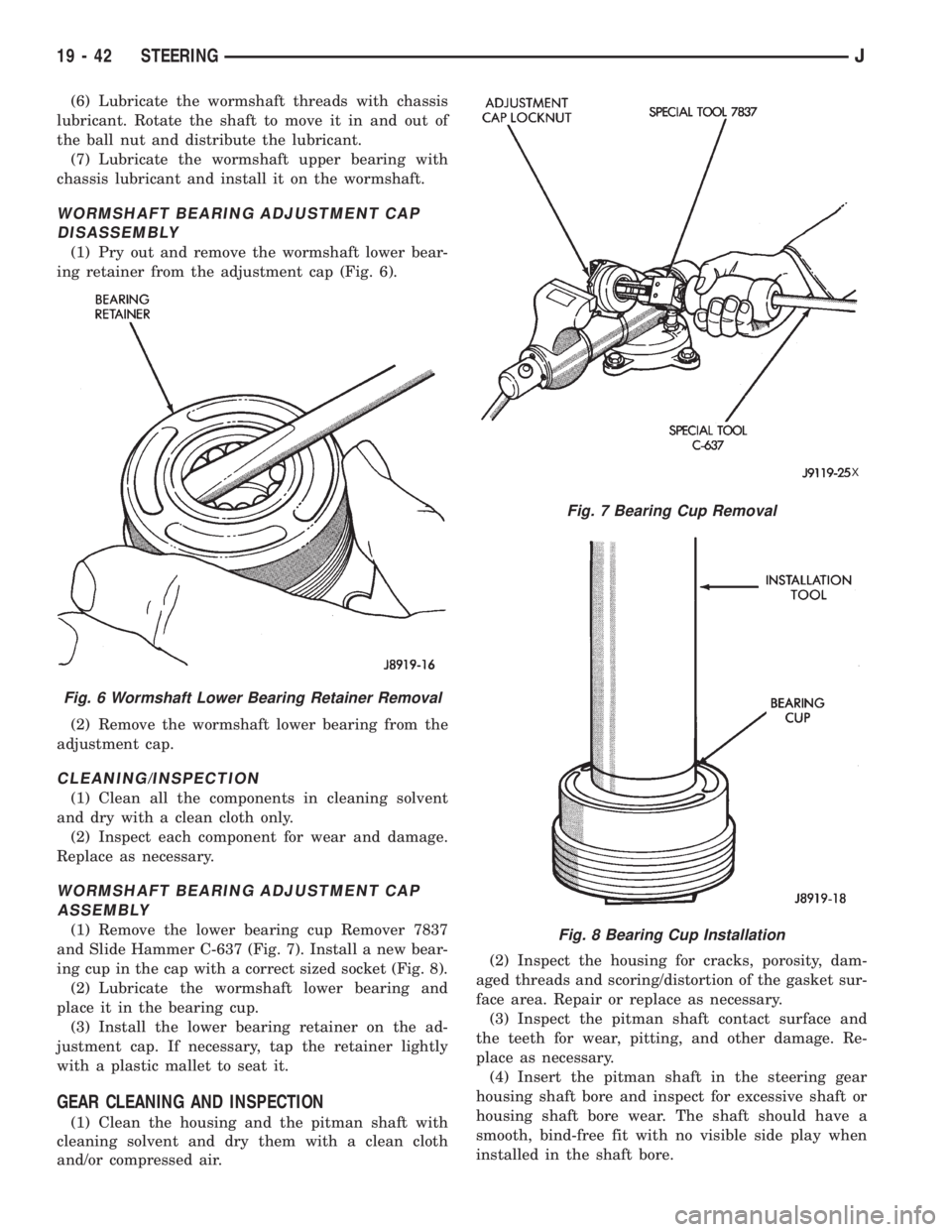
(1) Pry out and remove the wormshaft lower bear-
ing retainer from the adjustment cap (Fig. 6).
(2) Remove the wormshaft lower bearing from the
adjustment cap.
CLEANING/INSPECTION
(1) Clean all the components in cleaning solvent
and dry with a clean cloth only.
(2) Inspect each component for wear and damage.
Replace as necessary.
WORMSHAFT BEARING ADJUSTMENT CAP
ASSEMBLY
(1) Remove the lower bearing cup Remover 7837
and Slide Hammer C-637 (Fig. 7). Install a new bear-
ing cup in the cap with a correct sized socket (Fig. 8).
(2) Lubricate the wormshaft lower bearing and
place it in the bearing cup.
(3) Install the lower bearing retainer on the ad-
justment cap. If necessary, tap the retainer lightly
with a plastic mallet to seat it.
GEAR CLEANING AND INSPECTION
(1) Clean the housing and the pitman shaft with
cleaning solvent and dry them with a clean cloth
and/or compressed air.(2) Inspect the housing for cracks, porosity, dam-
aged threads and scoring/distortion of the gasket sur-
face area. Repair or replace as necessary.
(3) Inspect the pitman shaft contact surface and
the teeth for wear, pitting, and other damage. Re-
place as necessary.
(4) Insert the pitman shaft in the steering gear
housing shaft bore and inspect for excessive shaft or
housing shaft bore wear. The shaft should have a
smooth, bind-free fit with no visible side play when
installed in the shaft bore.
Fig. 6 Wormshaft Lower Bearing Retainer Removal
Fig. 7 Bearing Cup Removal
X
Fig. 8 Bearing Cup Installation
19 - 42 STEERINGJ
Page 1342 of 2198
(5) If the shaft fit is loose but it is not visibly
worn, trial fit a replacement pitman shaft in the
housing shaft bore. If the replacement shaft also has
a loose fit, replace the housing. However, if the re-
placement pitman fits properly, replace the original
pitman shaft.
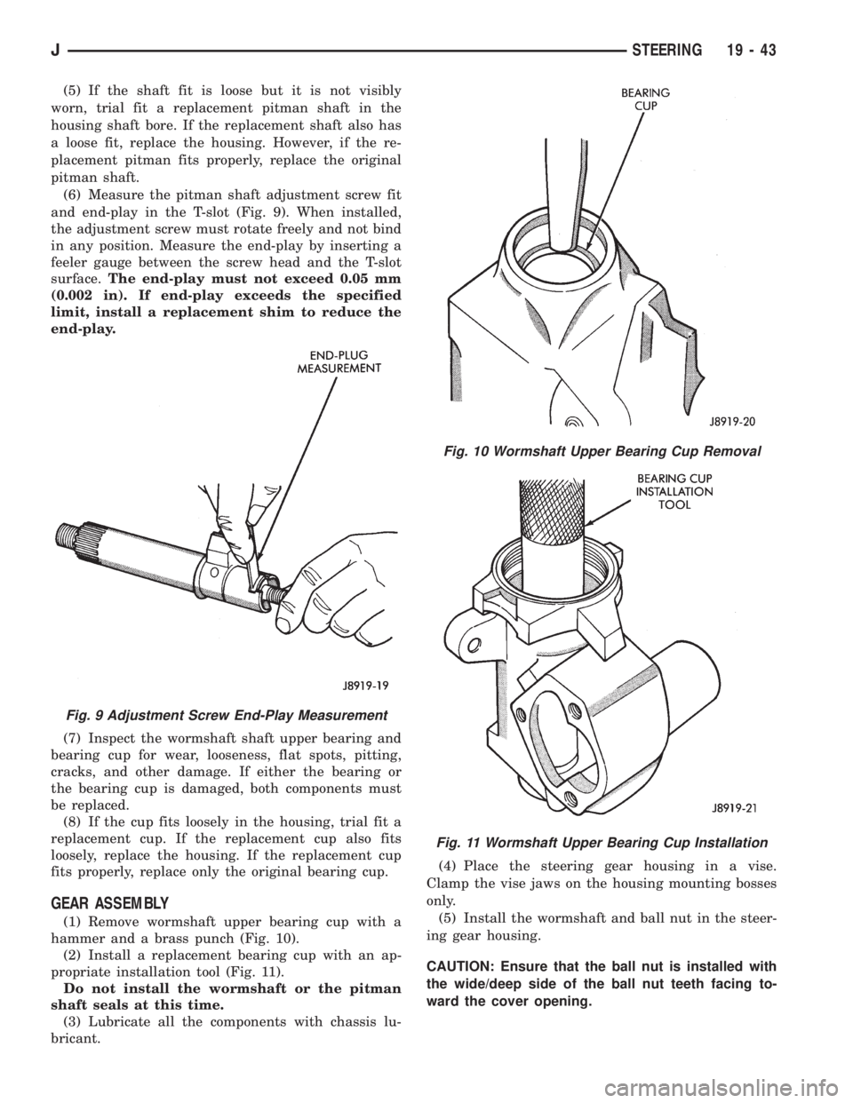
(6) Measure the pitman shaft adjustment screw fit
and end-play in the T-slot (Fig. 9). When installed,
the adjustment screw must rotate freely and not bind
in any position. Measure the end-play by inserting a
feeler gauge between the screw head and the T-slot
surface.The end-play must not exceed 0.05 mm
(0.002 in). If end-play exceeds the specified
limit, install a replacement shim to reduce the
end-play.
(7) Inspect the wormshaft shaft upper bearing and
bearing cup for wear, looseness, flat spots, pitting,
cracks, and other damage. If either the bearing or
the bearing cup is damaged, both components must
be replaced.
(8) If the cup fits loosely in the housing, trial fit a
replacement cup. If the replacement cup also fits
loosely, replace the housing. If the replacement cup
fits properly, replace only the original bearing cup.
GEAR ASSEMBLY
(1) Remove wormshaft upper bearing cup with a
hammer and a brass punch (Fig. 10).
(2) Install a replacement bearing cup with an ap-
propriate installation tool (Fig. 11).
Do not install the wormshaft or the pitman
shaft seals at this time.
(3) Lubricate all the components with chassis lu-
bricant.(4) Place the steering gear housing in a vise.
Clamp the vise jaws on the housing mounting bosses
only.
(5) Install the wormshaft and ball nut in the steer-
ing gear housing.
CAUTION: Ensure that the ball nut is installed with
the wide/deep side of the ball nut teeth facing to-
ward the cover opening.
Fig. 9 Adjustment Screw End-Play Measurement
Fig. 10 Wormshaft Upper Bearing Cup Removal
Fig. 11 Wormshaft Upper Bearing Cup Installation
JSTEERING 19 - 43
Page 1343 of 2198
(6) Install the wormshaft bearing adjustment cap
in the housing and tighten it only enough to remove
the wormshaft end-play.
(7) Install the locknut on the wormshaft bearing
adjustment cap but do not tighten it at this time.
(8) Pack the steering gear housing with as much
chassis lubricant as possible.
Rotate the wormshaft in one direction until
the ball nut ceases. Pack the end of the housing
full of lubricant, rotate the shaft in the opposite
direction and repeat the packing procedure.
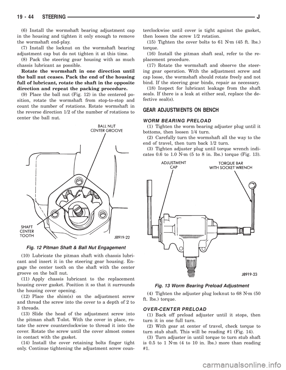
(9) Place the ball nut (Fig. 12) in the centered po-
sition, rotate the wormshaft from stop-to-stop and
count the number of rotations. Rotate wormshaft in
the reverse direction 1/2 of the number of rotations to
center the ball nut.
(10) Lubricate the pitman shaft with chassis lubri-
cant and insert it in the steering gear housing. En-
gage the center tooth on the shaft with the center
groove on the ball nut.
(11) Apply chassis lubricant to the replacement
housing cover gasket. Position it so that it surrounds
the housing cover opening.
(12) Place the shim(s) on the adjustment screw
and thread the screw into the cover to a depth of 2 to
3 threads.
(13) Slide the head of the adjustment screw into
the pitman shaft T-slot. With the cover in place, ro-
tate the screw counterclockwise to thread it into the
cover. Rotate the screw until the cover almost comes
in contact with the gasket.
(14) Install the cover retaining bolts finger tight
only. Continue tightening the adjustment screw coun-terclockwise until cover is tight against the gasket,
then loosen the screw 1/2 rotation.
(15) Tighten the cover bolts to 61 Nzm (45 ft. lbs.)
torque.
(16) Install the pitman shaft seal, refer to the re-
placement procedure.
(17) Rotate the wormshaft and observe the steer-
ing gear operation. With the adjustment screw and
cap loose, the wormshaft should rotate freely and not
bind. If the steering gear binds, repair as necessary.
(18) Inspect for lubricant leakage from the shaft
seals. If there is a leak at either seal, replace the de-
fective seal(s).
GEAR ADJUSTMENTS ON BENCH
WORM BEARING PRELOAD
(1) Tighten the worm bearing adjuster plug until it
bottoms, then loosen 1/4 turn.
(2) Carefully turn the wormshaft all the way to the
end of travel, then turn back 1/2 turn.
(3) Tighten adjuster plug until torque wrench indi-
cates 0.6 to 1.0 Nzm (5 to 8 in. lbs.) torque (Fig. 13).
(4) Tighten the adjuster plug locknut to 68 Nzm (50
ft. lbs.) torque.
OVER-CENTER PRELOAD
(1) Back off preload adjuster until it stops, then
turn it in one full turn.
(2) With gear at center of travel, check torque to
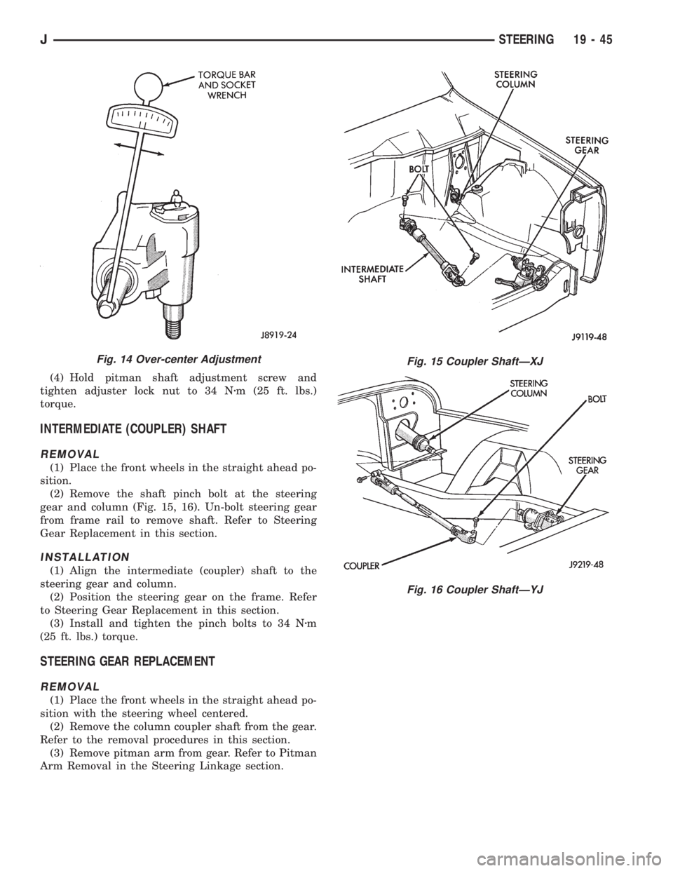
turn stub shaft. This will be reading #1 (Fig. 14).
(3) Turn adjuster in until torque to turn stub shaft
is 0.5 to 1 Nzm (4 to 10 in. lbs.) more than reading
#1.
Fig. 12 Pitman Shaft & Ball Nut Engagement
Fig. 13 Worm Bearing Preload Adjustment
19 - 44 STEERINGJ
Page 1344 of 2198
(4) Hold pitman shaft adjustment screw and
tighten adjuster lock nut to 34 Nzm (25 ft. lbs.)
torque.
INTERMEDIATE (COUPLER) SHAFT
REMOVAL
(1) Place the front wheels in the straight ahead po-
sition.
(2) Remove the shaft pinch bolt at the steering
gear and column (Fig. 15, 16). Un-bolt steering gear
from frame rail to remove shaft. Refer to Steering
Gear Replacement in this section.
INSTALLATION
(1) Align the intermediate (coupler) shaft to the
steering gear and column.
(2) Position the steering gear on the frame. Refer
to Steering Gear Replacement in this section.
(3) Install and tighten the pinch bolts to 34 Nzm
(25 ft. lbs.) torque.
STEERING GEAR REPLACEMENT
REMOVAL
(1) Place the front wheels in the straight ahead po-
sition with the steering wheel centered.
(2) Remove the column coupler shaft from the gear.
Refer to the removal procedures in this section.
(3) Remove pitman arm from gear. Refer to Pitman
Arm Removal in the Steering Linkage section.
Fig. 14 Over-center AdjustmentFig. 15 Coupler ShaftÐXJ
Fig. 16 Coupler ShaftÐYJ
JSTEERING 19 - 45
Page 1345 of 2198
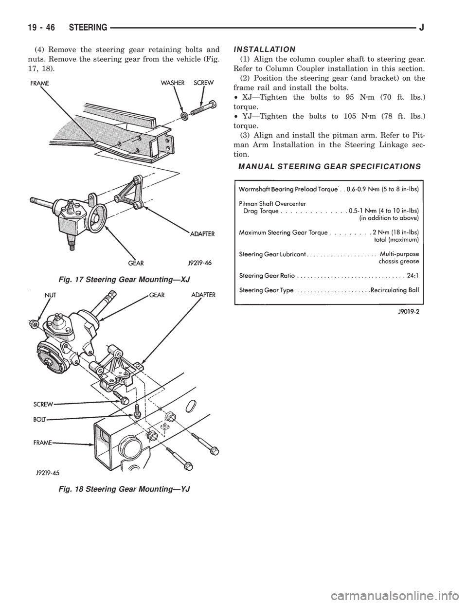
(4) Remove the steering gear retaining bolts and
nuts. Remove the steering gear from the vehicle (Fig.
17, 18).INSTALLATION
(1) Align the column coupler shaft to steering gear.
Refer to Column Coupler installation in this section.
(2) Position the steering gear (and bracket) on the
frame rail and install the bolts.
²XJÐTighten the bolts to 95 Nzm (70 ft. lbs.)
torque.
²YJÐTighten the bolts to 105 Nzm (78 ft. lbs.)
torque.
(3) Align and install the pitman arm. Refer to Pit-
man Arm Installation in the Steering Linkage sec-
tion.
Fig. 17 Steering Gear MountingÐXJ
Fig. 18 Steering Gear MountingÐYJ
MANUAL STEERING GEAR SPECIFICATIONS
19 - 46 STEERINGJ
Page 1346 of 2198
STEERING COLUMN GENERAL SERVICEÐXJ
INDEX
page
Airbag System........................... 47
AIRBAG SYSTEM
WARNING: THE MECHANICAL AIRBAG SYSTEM IS
A SENSITIVE, COMPLEX MECHANICAL UNIT. BE-
FORE ATTEMPTING TO REMOVE OR INSTALL THE
AIRBAG SYSTEM OR RELATED STEERING WHEEL
AND STEERING COLUMN COMPONENTS YOU
MUST FIRST DISARM THE AIRBAG FIRING MECHA-
NISM. FAILURE TO DO SO COULD RESULT IN AC-
CIDENTAL DEPLOYMENT AND POSSIBLE INJURY.
WARNING: THE AIRBAG MODULE INFLATOR/SEN-
SOR ASSEMBLY CONTAINS SODIUM AZIDE AND
POTASSIUM NITRATE. THESE MATERIALS ARE
POISONOUS AND EXTREMELY FLAMMABLE. CON-
TACT WITH ACID, WATER OR HEAVY METALS MAY
PRODUCE HARMFUL AND IRRITATING GASES (SO-
DIUM HYDROXIDE IS FORMED IN THE PRESENCE
OF MOISTURE) OR COMBUSTIBLE COMPOUNDS.
DO NOT ATTEMPT TO DISMANTLE THE MODULE
OR TAMPER WITH ITS ARMING LEVER. DO NOT
PUNCTURE, INCINERATE, OR BRING INTO CON-
TACT WITH ELECTRICITY. DO NOT STORE AT TEM-
PERATURES EXCEEDING 200ÉF.WARNING: REPLACE AIRBAG SYSTEM COMPO-
NENTS WITH PARTS SPECIFIED IN THE CHRYSLER
MOPAR PARTS CATALOG ONLY. IT IS OF PARTICU-
LAR IMPORTANCE THAT ANY COMPONENTS USED
IN THIS MECHANICALLY-FIRED AIRBAG SYSTEM
NOT BE MIXED WITH COMPONENTS FROM AN
ELECTRICALLY-FIRED AIRBAG SYSTEM. SUBSTI-
TUTE PARTS MAY APPEAR THE SAME, BUT INTER-
NAL DIFFERENCES MAY RESULT IN INFERIOR
OCCUPANT PROTECTION.
WARNING: THE FASTENERS, SCREWS, AND
BOLTS, ORIGINALLY USED FOR THE AIRBAG COM-
PONENTS, HAVE SPECIAL COATINGS AND ARE
SPECIFICALLY DESIGNED FOR THE AIRBAG SYS-
TEM. THEY MUST NEVER BE REPLACED WITH ANY
SUBSTITUTES. ANYTIME A NEW FASTENER IS
NEEDED, REPLACE WITH THE CORRECT FASTEN-
ERS PROVIDED IN THE SERVICE PACKAGE OR
SPECIFIED IN THE CHRYSLER MOPAR PARTS CAT-
ALOG.
JSTEERING 19 - 47
Page 1347 of 2198
GENERAL INFORMATION
The airbag system is a standard equipment safety
device on XJ (Cherokee) models. It is designed to pro-
tect the driver from serious injury, caused by a fron-
tal impact of the vehicle. If the airbag module
assembly is defective and non-deployed, refer to
Chrysler Corporation current return list for proper
handling procedures.
ARMING/DISARMING MECHANISM
BEFORE SERVICING A COLUMN EQUIPPED
WITH AIR BAG, REFER TO GROUP 8M, ELEC-
TRICAL FOR PROPER AND SAFE PROCE-
DURES.
The steering wheel hub incorporates an airbag
Arming/Disarming mechanism and a specially de-
signed nut-blocker. The nut-blocker serves as a safety
to prevent removal of the airbag module until the
unit has been disarmed. A removable plastic cover
plug on the top, outer hub of the steering wheel al-
lows access to the arming screw.
When the airbag module is disarmed, the arming
screw extends upward from the steering wheel hub.
This will prevent installation of the plastic cover
plug. Also, the nut-blocker is retracted to allow ac-
cess to the two upper airbag module mounting nuts.
When the airbag module is armed, the plastic cover
plug will install flush with the outer surface of the
steering wheel hub. In addition, the nut-blocker will
prevent access to the two upper airbag module
mounting nuts.THE FASTENERS, SCREWS, AND BOLTS, ORIG-
INALLY USED FOR THE AIR BAG COMPONENTS,
HAVE SPECIAL COATINGS. THIS HARDWARE IS
SPECIFICALLY DESIGNED FOR THE AIR BAG
SYSTEM. THEY MUST NEVER BE REPLACED
WITH ANY SUBSTITUTES. REPLACE WITH THE
CORRECT FASTENERS PROVIDED IN THE SER-
VICE PACKAGE OR FASTENERS IN THE PARTS
BOOK.
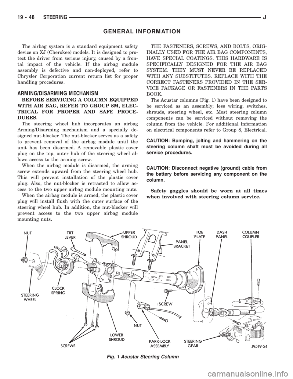
The Acustar columns (Fig. 1) have been designed to
be serviced as an assembly; less wiring, switches,
shrouds, steering wheel, etc. Most steering column
components can be serviced without removing the
column from the vehicle. For additional information
on electrical components refer to Group 8, Electrical.
CAUTION: Bumping, jolting and hammering on the
steering column shaft must be avoided during all
service procedures.
CAUTION: Disconnect negative (ground) cable from
the battery before servicing any component on the
column.
Safety goggles should be worn at all times
when involved with steering column service.
Fig. 1 Acustar Steering Column
19 - 48 STEERINGJ
Page 1348 of 2198
AIRBAG MODULE REMOVEÐINSTALL
WARNING: THIS AIRBAG SYSTEM IS A SENSITIVE,
COMPLEX MECHANICAL UNIT. BEFORE ATTEMPT-
ING TO REMOVE OR INSTALL THE AIRBAG SYS-
TEM OR RELATED STEERING WHEEL AND
STEERING COLUMN COMPONENTS YOU MUST
FIRST DISARM THE AIRBAG FIRING MECHANISM.
FAILURE TO DO SO COULD RESULT IN ACCIDEN-
TAL DEPLOYMENT AND POSSIBLE PERSONAL IN-
JURY.
When removing a deployed airbag module,
rubber gloves, eye protection and long-sleeved
shirt should be worn. There may be deposits on
the airbag module and other interior surfaces,
which can cause irritation to the skin and eyes
in large doses.
(1) Disconnect battery negative cable and isolate.
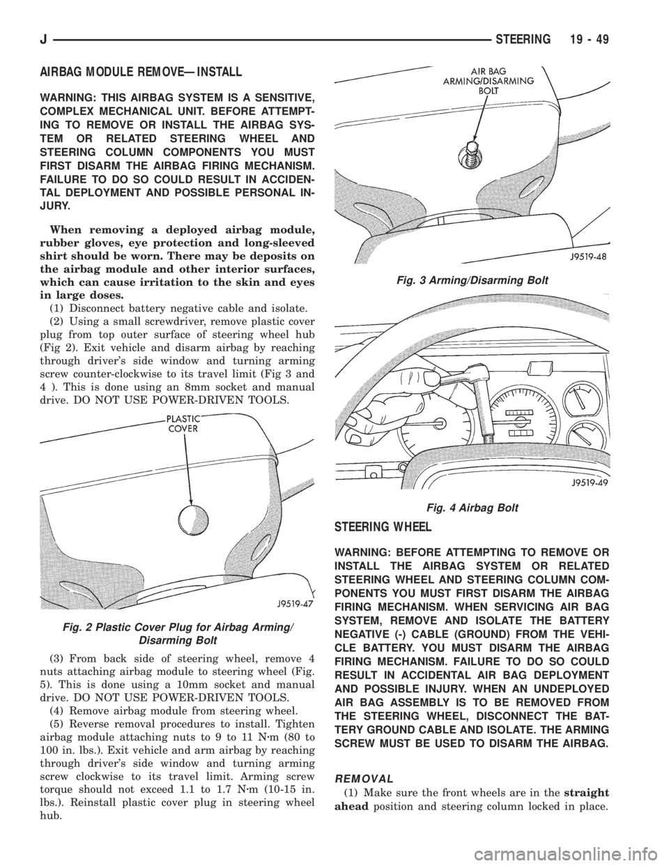
(2) Using a small screwdriver, remove plastic cover
plug from top outer surface of steering wheel hub
(Fig 2). Exit vehicle and disarm airbag by reaching
through driver's side window and turning arming
screw counter-clockwise to its travel limit (Fig 3 and
4 ). This is done using an 8mm socket and manual
drive. DO NOT USE POWER-DRIVEN TOOLS.
(3) From back side of steering wheel, remove 4
nuts attaching airbag module to steering wheel (Fig.
5). This is done using a 10mm socket and manual
drive. DO NOT USE POWER-DRIVEN TOOLS.
(4) Remove airbag module from steering wheel.
(5) Reverse removal procedures to install. Tighten
airbag module attaching nuts to 9 to 11 Nzm (80 to
100 in. lbs.). Exit vehicle and arm airbag by reaching
through driver's side window and turning arming
screw clockwise to its travel limit. Arming screw
torque should not exceed 1.1 to 1.7 Nzm (10-15 in.
lbs.). Reinstall plastic cover plug in steering wheel
hub.
STEERING WHEEL
WARNING: BEFORE ATTEMPTING TO REMOVE OR
INSTALL THE AIRBAG SYSTEM OR RELATED
STEERING WHEEL AND STEERING COLUMN COM-
PONENTS YOU MUST FIRST DISARM THE AIRBAG
FIRING MECHANISM. WHEN SERVICING AIR BAG
SYSTEM, REMOVE AND ISOLATE THE BATTERY
NEGATIVE (-) CABLE (GROUND) FROM THE VEHI-
CLE BATTERY. YOU MUST DISARM THE AIRBAG
FIRING MECHANISM. FAILURE TO DO SO COULD
RESULT IN ACCIDENTAL AIR BAG DEPLOYMENT
AND POSSIBLE INJURY. WHEN AN UNDEPLOYED
AIR BAG ASSEMBLY IS TO BE REMOVED FROM
THE STEERING WHEEL, DISCONNECT THE BAT-
TERY GROUND CABLE AND ISOLATE. THE ARMING
SCREW MUST BE USED TO DISARM THE AIRBAG.
REMOVAL
(1) Make sure the front wheels are in thestraight
aheadposition and steering column locked in place.
Fig. 2 Plastic Cover Plug for Airbag Arming/
Disarming Bolt
Fig. 3 Arming/Disarming Bolt
Fig. 4 Airbag Bolt
JSTEERING 19 - 49
Page 1349 of 2198
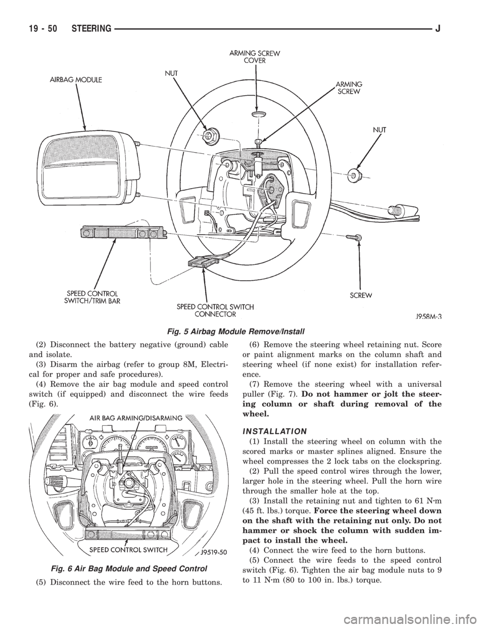
(2) Disconnect the battery negative (ground) cable
and isolate.
(3) Disarm the airbag (refer to group 8M, Electri-
cal for proper and safe procedures).
(4) Remove the air bag module and speed control
switch (if equipped) and disconnect the wire feeds
(Fig. 6).
(5) Disconnect the wire feed to the horn buttons.(6) Remove the steering wheel retaining nut. Score
or paint alignment marks on the column shaft and
steering wheel (if none exist) for installation refer-
ence.
(7) Remove the steering wheel with a universal
puller (Fig. 7).Do not hammer or jolt the steer-
ing column or shaft during removal of the
wheel.
INSTALLATION
(1) Install the steering wheel on column with the
scored marks or master splines aligned. Ensure the
wheel compresses the 2 lock tabs on the clockspring.
(2) Pull the speed control wires through the lower,
larger hole in the steering wheel. Pull the horn wire
through the smaller hole at the top.
(3) Install the retaining nut and tighten to 61 Nzm
(45 ft. lbs.) torque.Force the steering wheel down
on the shaft with the retaining nut only. Do not
hammer or shock the column with sudden im-
pact to install the wheel.
(4) Connect the wire feed to the horn buttons.
(5) Connect the wire feeds to the speed control
switch (Fig. 6). Tighten the air bag module nuts to 9
to 11 Nzm (80 to 100 in. lbs.) torque.
Fig. 5 Airbag Module Remove/Install
Fig. 6 Air Bag Module and Speed Control
19 - 50 STEERINGJ
Page 1350 of 2198
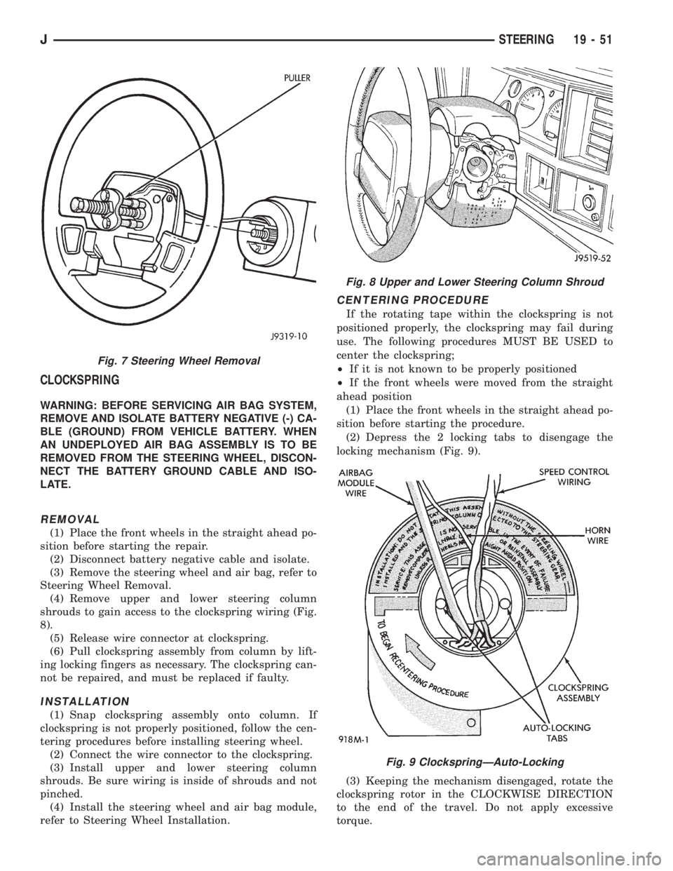
CLOCKSPRING
WARNING: BEFORE SERVICING AIR BAG SYSTEM,
REMOVE AND ISOLATE BATTERY NEGATIVE (-) CA-
BLE (GROUND) FROM VEHICLE BATTERY. WHEN
AN UNDEPLOYED AIR BAG ASSEMBLY IS TO BE
REMOVED FROM THE STEERING WHEEL, DISCON-
NECT THE BATTERY GROUND CABLE AND ISO-
LATE.
REMOVAL
(1) Place the front wheels in the straight ahead po-
sition before starting the repair.
(2) Disconnect battery negative cable and isolate.
(3) Remove the steering wheel and air bag, refer to
Steering Wheel Removal.
(4) Remove upper and lower steering column
shrouds to gain access to the clockspring wiring (Fig.
8).
(5) Release wire connector at clockspring.
(6) Pull clockspring assembly from column by lift-
ing locking fingers as necessary. The clockspring can-
not be repaired, and must be replaced if faulty.
INSTALLATION
(1) Snap clockspring assembly onto column. If
clockspring is not properly positioned, follow the cen-
tering procedures before installing steering wheel.
(2) Connect the wire connector to the clockspring.
(3) Install upper and lower steering column
shrouds. Be sure wiring is inside of shrouds and not
pinched.
(4) Install the steering wheel and air bag module,
refer to Steering Wheel Installation.
CENTERING PROCEDURE
If the rotating tape within the clockspring is not
positioned properly, the clockspring may fail during
use. The following procedures MUST BE USED to
center the clockspring;
²If it is not known to be properly positioned
²If the front wheels were moved from the straight
ahead position
(1) Place the front wheels in the straight ahead po-
sition before starting the procedure.
(2) Depress the 2 locking tabs to disengage the
locking mechanism (Fig. 9).
(3) Keeping the mechanism disengaged, rotate the
clockspring rotor in the CLOCKWISE DIRECTION
to the end of the travel. Do not apply excessive
torque.
Fig. 7 Steering Wheel Removal
Fig. 8 Upper and Lower Steering Column Shroud
Fig. 9 ClockspringÐAuto-Locking
JSTEERING 19 - 51