check engine JEEP CJ 1953 Owners Manual
[x] Cancel search | Manufacturer: JEEP, Model Year: 1953, Model line: CJ, Model: JEEP CJ 1953Pages: 376, PDF Size: 19.96 MB
Page 158 of 376
F2
EXHAUST EMISSION CONTROL SYSTEMS
F2-3L
EXHAUST EMISSION CONTROL SYSTEM
DIAGNOSIS
GUIDE
Pump Noisy
Hoses Touching Other Parts of Engine or Body (Hood).
Note:
The Air Pump is not completely noiseless.
Under
normal conditions, pump
noise
rises in pitch as
engine
speed
increases. It is desirable to allow
for normal break-in wear of the pump prior to re
placement for
excessive
noise.
Pump Seized
Replace pump.
-
do not pry on housing.
Leak
In Hose
Check
for leaks; using
soap
and water, tighten clamps or replace
hoses.
Pump Inoperative
Loose Belt — tighten belt
-
Filter
Plugged — replace.
Exhaust
Backfire
Check
for vacuum leaks — correct as necessary.
Check
anti-backfire valve — replace as necessary
Induction System Backfire
Verify
engine
timing and distributor dwell.
Verify
accelerator pump charge.
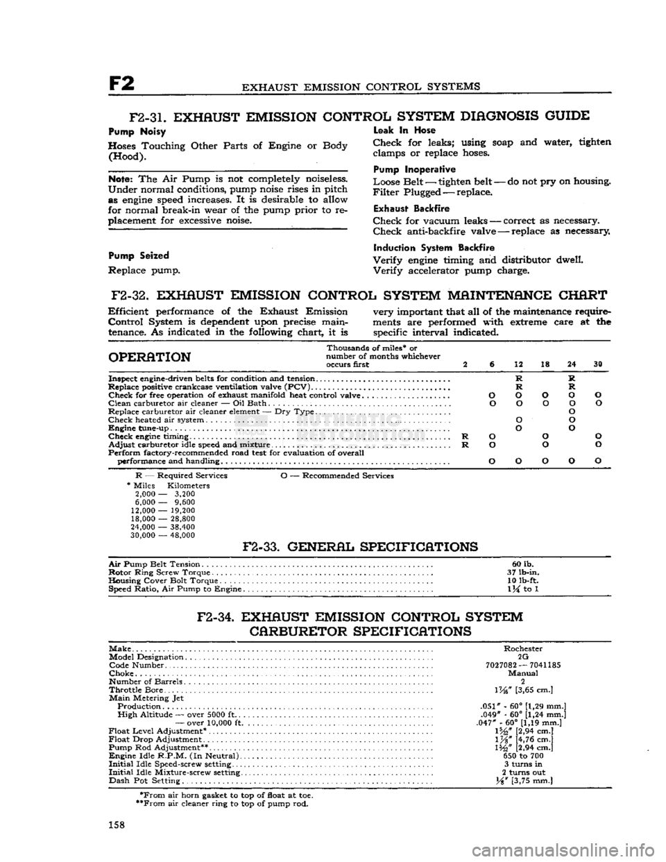
F2-32.
EXHAUST EMISSION CONTROL SYSTEM MAINTENANCE CHART
Efficient
performance of the Exhaust Emission very important that all of the maintenance require-
Control
System is
dependent
upon precise main-
ments
are performed with extreme care at the
tenance. As indicated in the following chart, it is specific interval indicated.
Thousands of miles* or
OPERATION
number of months whichever occurs first 2 6 12 18 24 30
Inspect engine-driven
belts
for condition and tension R R
Replace positive crankcase ventilation valve
(PCV)
R R
Check
for free operation of exhaust manifold heat control valve O O O O O
Clean
carburetor air cleaner — Oil Bath O O O O O
Replace carburetor air cleaner
element
— Dry Type O
Check
heated air system O O
Engine
tune-up O O
Check
engine
timing R O O O
Adjust
carburetor idle
speed
and mixture R O O O
Perform
factory-recommended road
test
for evaluation of overall performance and handling O O O O O
R
— Required Services O — Recommended Services
*
Miles Kilometers
2,000
—
3,200
6,000
—
9,600
12,000
—
19,200 18,000
—
28,800
24,000
—
38,400
30,000
—
48,000
F2-33.
GENERAL SPECIFICATIONS
Air
Pump Belt Tension 60 lb.
Rotor
Ring Screw Torque . 37 lb-in.
Housing Cover Bolt Torque 10 lb-ft. Speed Ratio, Air Pump to Engine
1
\i to 1
F2-34.
EXHAUST EMISSION CONTROL SYSTEM CARBURETOR SPECIFICATIONS
Make
Rochester Model Designation 2G Code Number
7027082
—
7041185
Choke
Manual
Number of Barrels 2
Throttle
Bore... \W [3,65 cm.]
Main
Metering Jet Production .051" - 60° [1,29 mm.]
High
Altitude — over
5000
ft .049" - 60° [1,24 mm.]
—
over
10,000
ft .047" - 60° [1,19 mm.]
Float
Level
Adjustment* 1%," [2,94 cm.]
Float
Drop Adjustment l%" [4,76 cm.]
Pump Rod Adjustment** 1%" [2,94 cm.]
Engine
Idle
R.P.M.
(In Neutral) 650 to 700
Initial
Idle Speed-screw
setting
3 turns in
Initial
Idle Mixture-screw
setting
2 turns out
Dash
Pot Setting. Y%w [3,75 mm.]
*From
air horn gasket to top of float at toe.
**From
air cleaner ring to top of pump rod.
158
Page 159 of 376
'Jeep'
UNIVERSAL SERIES SERVICE
MANUAL
F2
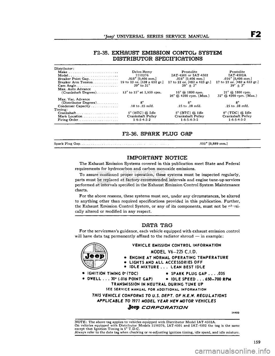
F2-35.
EXHAUST EMISSION CONTOL SYSTEM
DISTRIBUTOR SPECIFICATIONS
Distributor:
Make
Delco-Remy Prestolite Prestolite
Model...
1110376
IAT-4501 or IAT-4502 IAT-4502A
Breaker
Point Gap .016"
[0,406
mm.] .016"
[0,406
mm.] .016"
[0,406
mm.]
Breaker
Arm Tension 19 to 23 oz. [538 a 652 gr.] 17 to 22 oz. [482 a 623 gr.] 17 to 22 oz. [482 a 623 gr.]
Cam
Angle. 29° to 31° 29° + 3° 29° ± 3°
Max.
Auto Advance
(Crankshaft
Degrees). 13° to 15° at 1,950 rpm. 16° (& 1800 rpm. 21° @ 1800 rpm.
26°
@
4200
rpm. (Max.) 32° @
4200
rpm. (Max.)
Max.
Vac. Advance
(Distributor
Degrees) 8° 8° 8°
Condenser Capacity. .18 to .23 mfd. .25 to .28 mfd. .25 to .28 mfd.
Timing:
Crankshaft
5°
(BTC)
@ Idle 5°
(BTC)
© Idle 0°
(TDC)
© Idle
Mark
Location Crankshaft Pulley Crankshaft Pulley Crankshaft Pulley
Firing
Order
1-6-5-4-3-2 1-6-5-4-3-2 1-6-5-4-3-2
F2-36.
SPARK PLUG
GAP
Spark
Plug Gap. .035"
[0,889
mm.]
IMPORTANT
NOTICE
The
Exhaust Emission Systems covered in this publication
meet
State and Federal
requirements for hydrocarbon and carbon
monoxide
emissions.
To
assure continued proper operation,
these
systems
must be inspected regularly,
parts must be replaced at factory-recommended intervals and
engine
tune-up services
performed at intervals specified in the Exhaust Emission Control System Maintenance
charts.
For
the
above
reasons,
these
systems
must not, under any circumstances, be altered
to anything other than required specifications provided in this publication.
Further,
the Exhaust Emission Control System, or any of its components, must not be physi
cally
altered or modified in any respect.
DATA
TAG
For
the serviceman's guidance, each vehicle equipped with exhaust emission control
will
have data tag permanently affixed to the radiator shroud — in example:
VEHICLE EMISSION CONTROL INFORMATION MODEL V6-225 C.I.D.
•
ENGINE
AT
NORMAL OPERATING TEMPERATURE
•
LIGHTS
AND ALL
ACCESSORIES
OFF
•
IDLE MIXTURE
.. .
LEAN BEST IDLE
•
IGNITION TIMING
0*
(TDC)
*
SPARK PLUG
GAP 035
•
DWELL
. . . 30* (.016
POINT
GAP) •
IDLE SPEED
. . .
650- 700
RPM
TRANSMISSION
IN
NEUTRAL DURING TUNE
UP
SEE
SERVICE MANUAL FOR ADDITIONAL INFORMATION
THIS VEHICLE CONFORMS
TO U.S. DEPT. OF H.E.W.
REGULATIONS APPLICABLE
TO
1971
MODEL YEAR
NEW
MOTOR VEHICLES
Jeep
CORPORATION
14400
NOTE:
The
above
tag applies to vehicles equipped with Distributor Model
IAT-4502A.
On
vehicles equipped with Distributor Models
1110376,
IAT-4501 and IAT-4502 the tag is the same
except
that Ignition Timing is 5°
T.D.C.
Always
refer to the data tag when checking or re-adjusting ignition timing, idle speed, and idle mixture.
159
Page 162 of 376
COOLING
SYSTEM
14263
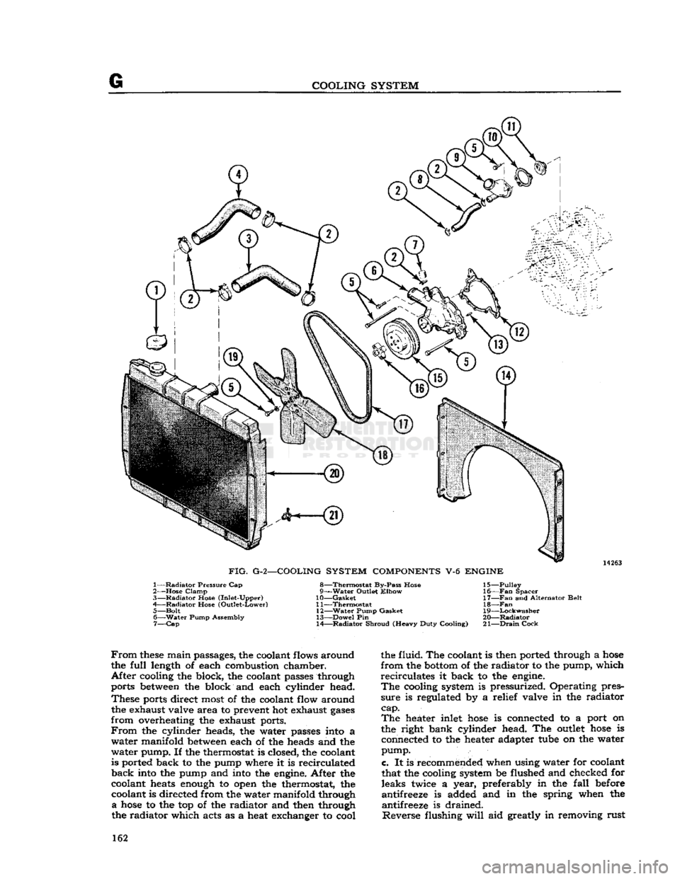
FIG.
G-2—COOLING SYSTEM
COMPONENTS
V-6
ENGINE
1—
Radiator
Pressure Cap
2—
Hose
Clamp
3—
Radiator
Hose (Inlet-Upper)
4—
Radiator
Hose (Outlet-Lower) 5—
Bolt
6—
Water
Pump Assembly 7—
Cap
8—Thermostat
By-Pass Hose
g—Water Outlet
Elbow
10—
Gasket
11—
Thermostat
12—
Water
Pump Gasket
13—
Dowel
Pin
14—
Radiator
Shroud (Heavy Duty Cooling) 15—
Pulley
16—
Fan
Spacer
17—
Fan
and Alternator Belt
18—Fan
19—
Lockwasher
20—
Radiator
21—
Drain
Cock
From
these
main passages, the coolant flows around
the
full
length of each combustion chamber.
After
cooling the block, the coolant passes through
ports between the block and each cylinder head.
These
ports direct most of the coolant flow around the exhaust valve area to prevent hot exhaust
gases
from
overheating the exhaust ports.
From
the cylinder heads, the water passes into a
water
manifold between each of the heads and the
water
pump. If the thermostat is closed, the coolant
is ported back to the pump where it is recirculated
back
into the pump and into the engine. After the
coolant heats enough to open the thermostat, the coolant is directed from the water manifold through
a
hose
to the top of the radiator and then through
the radiator which acts as a heat exchanger to cool the fluid. The coolant is then ported through a
hose
from
the bottom of the radiator to the pump, which
recirculates
it back to the engine.
The
cooling system is pressurized. Operating pres
sure
is regulated by a relief valve in the radiator
cap. The
heater inlet
hose
is connected to a port on
the right bank cylinder head. The outlet
hose
is connected to the heater adapter tube on the water
pump.
c.
It is recommended when using water for coolant
that the cooling system be flushed and checked for leaks twice a year, preferably in the
fall
before
antifreeze is added and in the spring when the antifreeze is drained.
Reverse
flushing
will
aid greatly in removing rust 162
Page 164 of 376
G
COOLING SYSTEM
engine
connections. Insert flushing gun and flush
heater core.
Care
must be taken when applying air
pressure to prevent damage to the heater core.
G-2.
Filling
Cooling System
To
fill
the cooling system, remove the
fill
cap and
fill
the tank to the top. Replace the cap and run
the
engine
at medium speed for approximately one
minute. Remove the cap and recheck the coolant level. Add more coolant if necessary to bring the level back to the top of the tank. If the cooling system is filled when the
engine
is cold, recheck the coolant level after the
engine
has warmed up.
This
will
ensure that the thermostat has opened allow ing complete cooling system circulation.
Always
correct any cooling system leaks before installing antifreeze. A corrosion inhibitor should be used in the cooling system to prevent the forma
tion of rust and scale. A quality brand antifreeze containing a corrosion inhibitor should be used.
When
the antifreeze is drained in the spring, a
corrosion inhibitor should be added with the water.
Note:
Cooling system components for both V6 and
F4
engines
are shown in
Figs.
G-2 and G-3.
G-3. Draining
Cooling System
To
completely
drain
the cooling system, open the
drain
in the
bottom
of the radiator and also a
drain
on the right side of the cylinder block on the
Hurricane
F4 engine. The Dauntless V-6
engine
has two
drain
plugs, one located on each side of the cylinder block. Both plugs must be removed to
completely
drain
the cooling system.
Remove the radiator cap to break any vacuum
that may have developed.
Should
the cooling solution be lost from the system
and
the
engine
become
overheated do not
refill
the system immediately but allow the
engine
to cool or
refill
slowly while the
engine
is running. If
cold solution is poured into the radiator while the
engine
is overheated there is danger of cracking the
cylinder
block and/or cylinder head.
G-4.
Radiator Pressure
Cap
All
radiators are equipped with pressure caps which
reduce evaporation of cooling solution and make the
engines
more efficient by permitting slightly
higher operating temperatures. When operating
properly,
the pressure cap permits pressure build-up
in
the cooling system during periods of severe heat
load.
This
pressure increases the boiling point of the coolant and thus reduces overflow losses. The
effectiveness
of the cap is limited by its opening
pressure and the boiling point of the coolant (see
note
below). The pressure cap employs a spring-
loaded, rubber-faced pressure seal which presses against a seat in the radiator top tank. Spring pres
sure
determines the opening pressure of the valve.
A
typical pressure cap is shown in Fig. G-5.
Note:
Refer to cooling system specifications (Par.
G-21)
for opening (relief) pressure when the ve
hicle is equipped with either the
Hurricane
F4
or
Dauntless V-6 engine. If a new cap is required, always install a cap of the same type and pressure
rating
specified. It should never be altered or re
placed by a plain cap.
A
vacuum release valve (Fig. G-5) is employed to
prevent undesirable vacuum build-up when the system
cools
down. The vacuum release valve is
held against its seat under light spring pressure.
Vacuum
in the system is relieved by the valve
which
opens
at V2 to 1 psi. [0,035 a 0,07 kg-cm2]
vacuum.
A pressure tester can be used to check and
test
the vacuum pressure rate (see Fig. G-6).
Although the mechanism of the pressure cap re quires no maintenance, the cap should be inspected
periodically for cleanliness and freedom of opera tion. The pressure cap gasket and radiator filler neck seat should also be inspected to be sure they
are
providing a proper seal. If the rubber face of
the valve is defective, a new cap should be installed.
Filler
neck reseating
tools
are commercially
avail
able to correct minor
defects
at the surface of the seat. Follow instructions of the reseating tool manu
facturer.
To
remove the radiator pressure cap when the
engine
coolant temperature is high or boiling, place
a
cloth over the pressure cap and
turn
counter clockwise about Vi
turn
until the first (pressure release)
stop
is reached. Keep the cap in this posi
tion until all pressure is released.
Then
push cap
down and
turn
still
further until cap can be re moved. To install the pressure cap, place it in posi
tion and
turn
it clockwise as far as it
will
go.
Caution:
Use extreme care in removing the radiator
pressure cap. In overheated systems, the sudden release of pressure can cause a steam flash and this
flash,
or the
loosened
cap can cause serious personal
injury.
G-5.
RADIATOR
Maintenance of the radiator consists of keeping
the exterior of the radiator core clean, the interior free from rust and scale, and the radiator free from
leaks.
Check
the cooling system fluid level and for
leaks each
2000
miles
[3.200
km.] or every 30
days, whichever occurs first.
This
exterior of the
radiator
core should be cleaned and the radiator inspected for leaks each
6000
miles
[9.600
km.]
of normal service of the vehicle. Cleaning should be performed by blowing out with air stream or water stream directed from the
rear
of the radiator.
Visual
inspection is not sufficient as the accumula tion of small particles of foreign material on core
surfaces can restrict cooling without closing the core openings.
Radiator
leakage occasionally results from cor
rosion perforation of the metal but most leakage results from mechanical failure of soldered joints
when too much strain has been put on the joint.
Fractures
occur most
often
at the joint where the
radiator
inlet and
outlet
pipes are attached to the
tanks.
When the seams break, the entire soldered
joint
is
exposed
and can corrode, but breakage
rather
than corrosion is the
primary
cause of seam
leakage. Examine the radiator carefully for leaks before and after cleaning. Cleaning may uncover points of leakage already existing but plugged with
rust.
White, rusty, or colored leakage stains indicate 164
Page 166 of 376
G
COOLING SYSTEM and
the outlet
hose
is connected to the water pump
housing.
When
installing a new hose, clean the pipe connec
tions and apply a thin layer of nonhardening seal
ing compound. Hose clamps should be properly
located over the connections to provide secure fastening. The pressurized cooling system pressure
can
blow off improperly installed hoses.
G-8.
Cylinder
Block
Any
coolant leaks at the engine block water joints
are
aggravated by pump pressure in the water
jacket
and by pressure developed in the cooling system when the pressure cap is in place.
Small
leaks showing up only as moist
spots
often
cannot
be detected when the engine is hot except by the
appearance of rust, corrosion, and dye stains where
leakage evaporated. Also, expansion and contrac tion of the engine block resulting from extreme
temperature changes can aggravate leaks. For
these
reasons, when checking for coolant leaks inspect
the block when it is cold and while the engine is
running.
A
leaking
drain
cock or plug that cannot be stopped
leaking
by tightening should be replaced.
Leaking
core-hole expansion plugs should be replaced.
If
tightening gasketed joints
will
not correct leak
age, install new gaskets. Use a sealing compound
where recommended.
G-9.
Thermostat
a.
The cooling system of the engine is designed
to provide adequate cooling under most adverse conditions. However, it is necessary to employ
some
device to provide quick warming and to prevent
overcooling during normal operation. Automatic
control
of engine operating temperature is provided
by a water flow control thermostat installed in the
water
outlet of the
Hurricane
F4 engine. The ther
mostat is a heat-operated valve. It should always
be maintained in working order and the vehicle
should never be driven without one installed as there would then be no control of engine tempera
ture.
The temperature at which the thermostat
opens
is preset and cannot be altered.
b.
The thermostat on the
Hurricane
F4 engine is
located in a housing on the top front of the cylinder
head.
On the Dauntless V-6 engine it is located
in
the thermostat housing of the air intake manifold.
The
standard engine thermostat for the
Hurricane
F4
and Dauntless V-6 engine has a normal rating
of
190°F.
[87.8°C]
and should begin to open at
a
coolant temperature between
180°F.
[82°C]
to
192°F.
[89°C]
and be fully open at
202°F.
[94°C.].
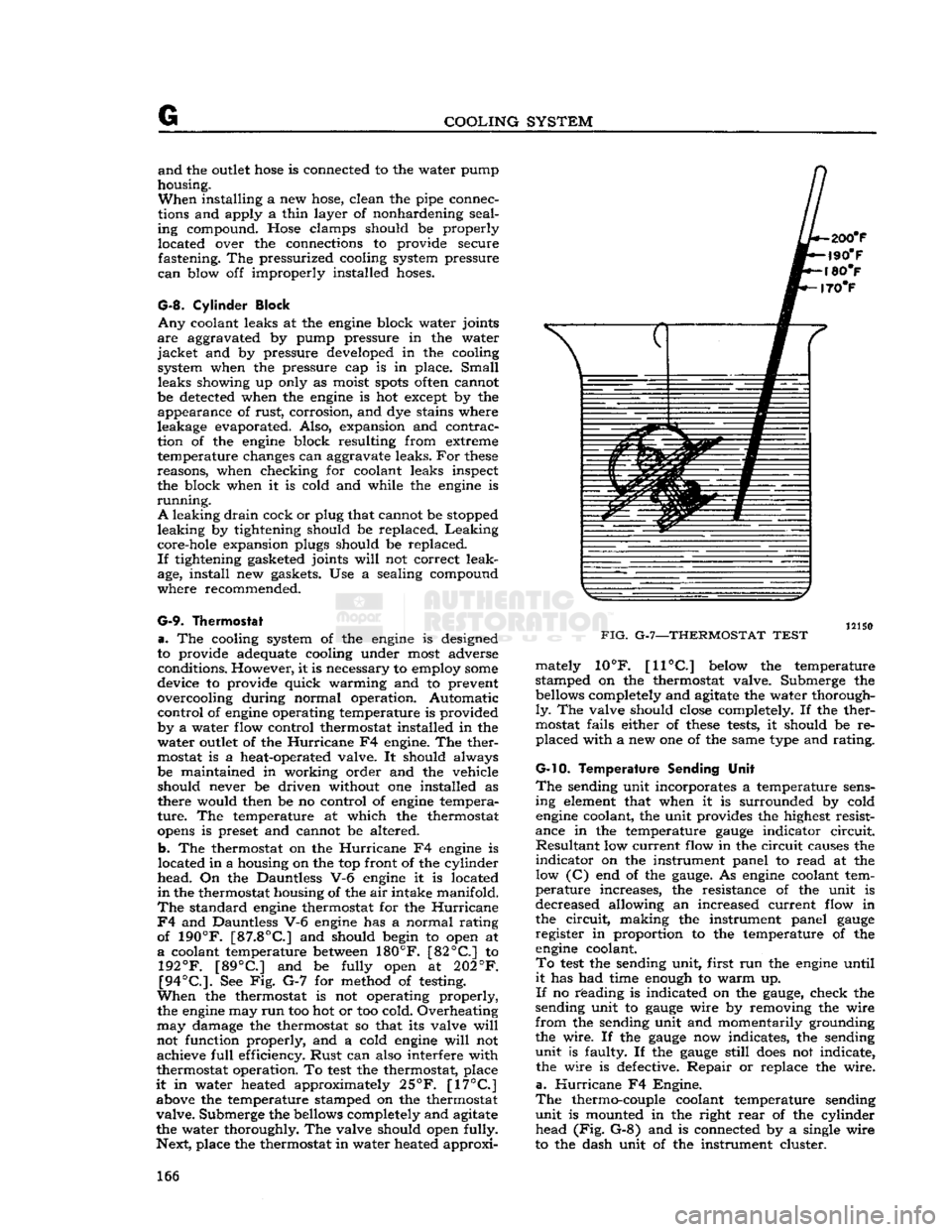
See Fig. G-7 for method of testing.
When
the thermostat is not operating properly, the engine may
run
too hot or too cold. Overheating
may
damage the thermostat so that its valve
will
not function properly, and a cold engine
will
not achieve
full
efficiency.
Rust
can also interfere with
thermostat operation. To
test
the thermostat, place
it
in water heated approximately
25°F.
[17°C]
above the temperature stamped on the thermostat
valve.
Submerge the bellows completely and agitate
the water thoroughly. The valve should open fully.
Next, place the thermostat in water heated approxi-
FIG.
G-7—THERMOSTAT
TEST
mately 10°F.
[11°C]
below the temperature
stamped on the thermostat valve. Submerge the bellows completely and agitate the water thorough
ly.
The valve should close completely. If the ther
mostat fails either of
these
tests, it should be re placed with a new one of the same type and rating.
G-10. Temperature
Sending Unit
The
sending unit incorporates a temperature sens ing element that when it is surrounded by cold engine coolant, the unit provides the highest resist
ance in the temperature
gauge
indicator
circuit.
Resultant
low current flow in the circuit causes the
indicator
on the instrument panel to read at the low (C) end of the
gauge.
As engine coolant tem
perature
increases, the resistance of the unit is
decreased allowing an increased current flow in
the
circuit,
making the instrument panel
gauge
register in proportion to the temperature of the engine coolant.
To
test
the sending unit, first run the engine until
it
has had time enough to warm up.
If
no reading is indicated on the
gauge,
check the
sending unit to
gauge
wire by removing the wire
from
the sending unit and momentarily grounding
the wire. If the
gauge
now indicates, the sending
unit
is faulty. If the
gauge
still
does
not indicate, the wire is defective.
Repair
or replace the wire,
a.
Hurricane
F4 Engine.
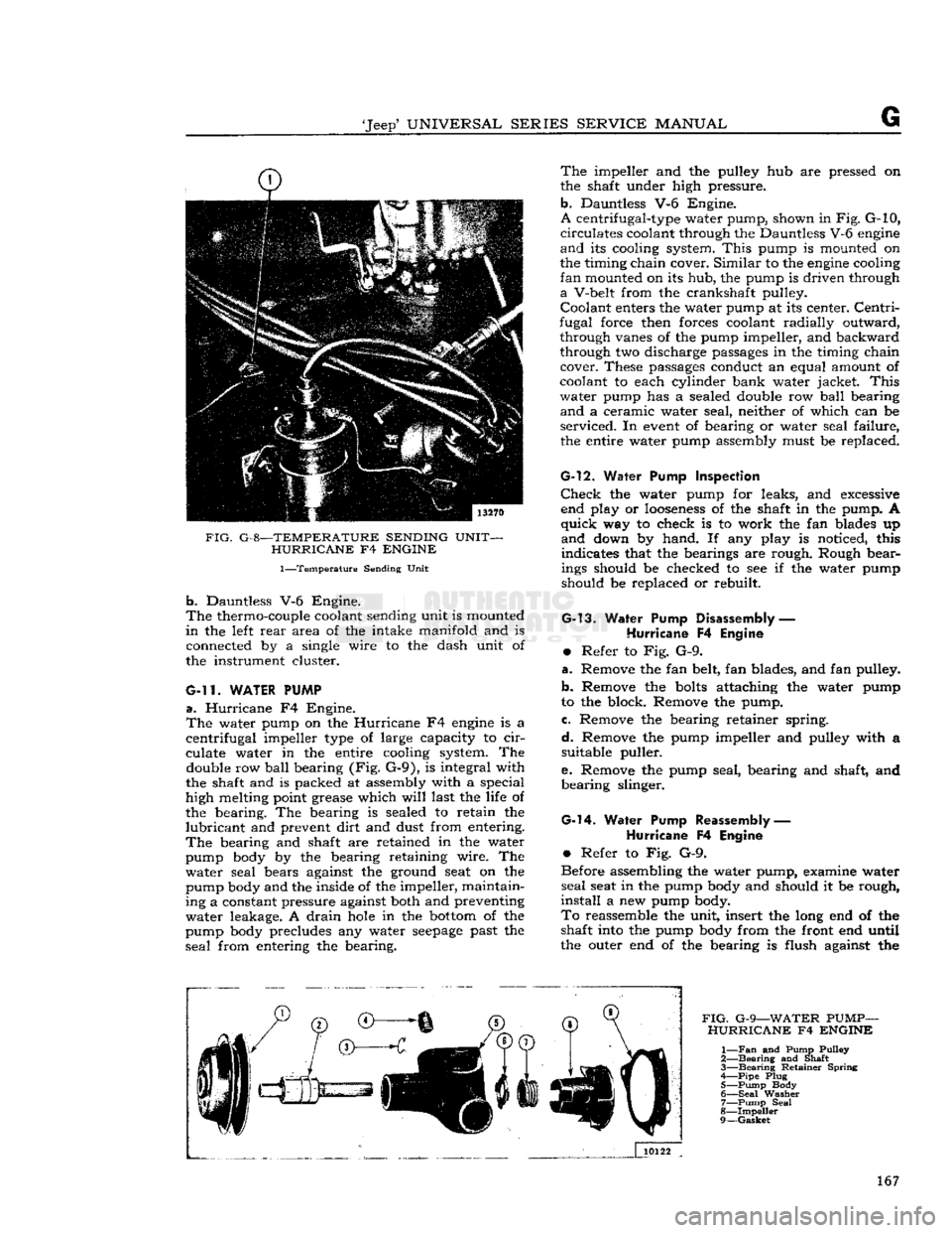
The
thermo-couple coolant temperature sending
unit
is mounted in the right
rear
of the cylinder head (Fig. G-8) and is connected by a single wire
to the dash unit of the instrument cluster. 166
Page 167 of 376
'Jeep*
UNIVERSAL
SERIES
SERVICE
MANUAL
FIG.
G-8—TEMPERATURE SENDING UNIT- HURRICANE
F4
ENGINE
1—Temperature
Sending Unit
b.
Dauntless V-6 Engine.
The
thermo-couple coolant sending unit is mounted
in
the left
rear
area of the intake manifold and is
connected by a single wire to the dash unit of
the instrument cluster.
G-ll.
WATER PUMP
a.
Hurricane
F4 Engine.
The
water pump on the
Hurricane
F4
engine
is a
centrifugal
impeller type of large capacity to
cir
culate water in the entire cooling system. The double row
ball
bearing (Fig. G-9), is integral with
the shaft and is packed at assembly with a special
high melting point grease which
will
last the life of
the bearing. The bearing is sealed to retain the
lubricant
and prevent
dirt
and dust from entering.
The
bearing and shaft are retained in the water
pump body by the bearing retaining wire. The
water
seal bears against the ground seat on the
pump body and the inside of the impeller, maintain
ing a constant pressure against both and preventing
water
leakage. A
drain
hole
in the
bottom
of the
pump body precludes any water
seepage
past the
seal
from entering the bearing.
The
impeller and the pulley hub are pressed on
the shaft under high pressure,
b.
Dauntless V-6 Engine.
A
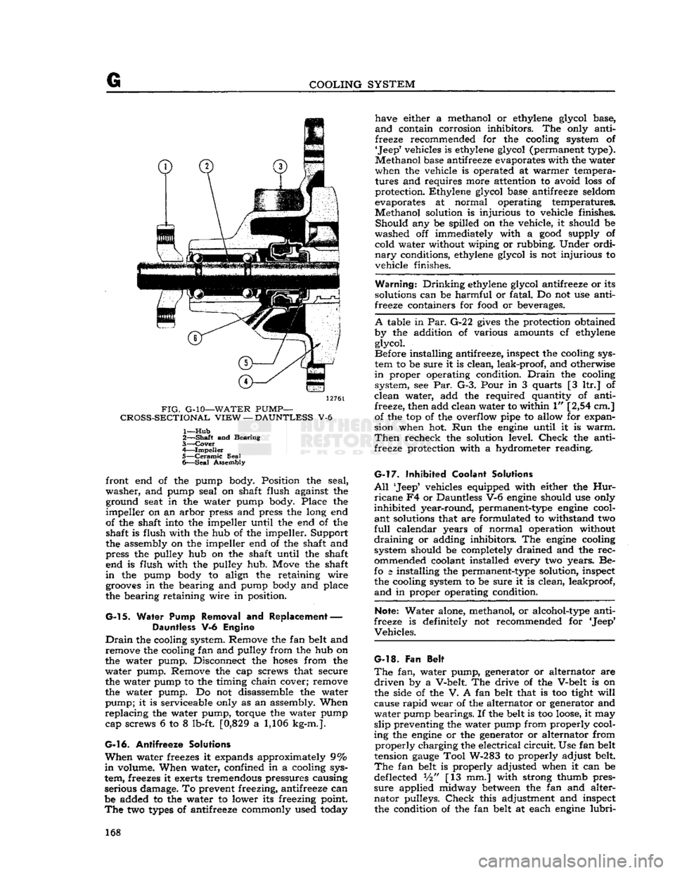
centrifugal-type water pump, shown in
Fig.
G-10,
circulates
coolant through the Dauntless V-6
engine
and
its cooling system.
This
pump is mounted on
the timing chain cover.
Similar
to the
engine
cooling
fan
mounted on its hub, the pump is driven through
a
V-belt from the crankshaft pulley.
Coolant
enters the water pump at its center.
Centri
fugal force then forces coolant radially outward, through vanes of the pump impeller, and backward
through two discharge passages in the timing chain cover. These passages conduct an equal amount of
coolant to each cylinder bank water jacket.
This
water
pump has a sealed double row
ball
bearing
and
a ceramic water seal, neither of which can be
serviced.
In
event
of bearing or water seal failure, the entire water pump assembly must be replaced.
G-l2.
Water
Pump Inspection
Check
the water pump for leaks, and excessive end play or
looseness
of the shaft in the pump. A
quick
way to check is to work the fan blades up
and
down by hand. If any play is noticed, this
indicates that the bearings are rough. Rough bearings should be checked to see if the water pump
should be replaced or rebuilt.
G-13.
Water Pump
Disassembly
—
Hurricane
F4
Engine
•
Refer to Fig. G-9.
a.
Remove the fan belt, fan blades, and fan pulley.
b.
Remove the
bolts
attaching the water pump
to the block. Remove the pump.
c.
Remove the bearing retainer spring.
d.
Remove the pump impeller and pulley with a suitable puller.
e.
Remove the pump seal, bearing and shaft, and
bearing
slinger.
G-l4.
Water Pump Reassembly
—
Hurricane
F4
Engine
•
Refer to Fig. G-9.
Before assembling the water pump, examine water
seal
seat in the pump body and should it be rough,
install
a new pump body.
To
reassemble the unit, insert the long end of the shaft into the pump body from the front end until
the outer end of the bearing is flush against the
FIG.
G-9—WATER
PUMP-
HURRICANE
F4
ENGINE
1—
Fan
and Pump Pulley
2—
Bearing
and Shaft
3—
Bearing
Retainer Spring
A—Pipe
Plug 5—
Pump
Body
6—
Seal
Washer 7—
Pump
Seal
8—
Impeller
9—
Gasket
167
Page 168 of 376
G
COOLING SYSTEM
12761
FIG.
G-10—WATER
PUMP—
CROSS-SECTIONAL
VIEW
—
DAUNTLESS
V-6
1—
Hub
2—
—Shaft
and Bearing
3—
Cover
4—
Impeller
5—
Ceramic
Seal
6—
Seal
Assembly front end of the pump body. Position the seal,
washer,
and pump seal on shaft flush against the ground seat in the water pump body. Place the
impeller
on an arbor press and press the long end
of the shaft into the impeller until the end of the shaft is flush with the hub of the impeller. Support
the assembly on the impeller end of the shaft and
press the pulley hub on the shaft until the shaft end is flush with the pulley hub. Move the shaft
in
the pump body to align the retaining wire
grooves
in the bearing and pump body and place
the bearing retaining wire in position.
G-l
5. Water Pump Removal and Replacement — Dauntless V-6 Engine
Drain
the cooling system. Remove the fan belt and remove the cooling fan and pulley from the hub on
the water pump. Disconnect the
hoses
from the
water
pump. Remove the cap screws that secure
the water pump to the timing chain cover; remove
the water pump. Do not disassemble the water
pump;
it is serviceable only as an assembly. When
replacing
the water pump, torque the water pump cap screws 6 to 8 lb-ft. [0,829 a 1,106 kg-m.].
G-16.
Antifreeze Solutions
When
water freezes it expands approximately 9%
in
volume. When water, confined in a cooling sys
tem, freezes it exerts tremendous pressures causing
serious damage. To prevent freezing, antifreeze can
be added to the water to lower its freezing point.
The
two
types
of antifreeze commonly used today have either a methanol or ethylene glycol base,
and
contain corrosion inhibitors. The only anti
freeze recommended for the cooling system of
'Jeep'
vehicles is ethylene glycol (permanent type).
Methanol
base antifreeze evaporates with the water
when the vehicle is operated at warmer tempera
tures and requires more attention to avoid
loss
of
protection. Ethylene glycol base antifreeze seldom
evaporates at normal operating temperatures.
Methanol
solution is injurious to vehicle finishes.
Should
any be spilled on the vehicle, it should be
washed off immediately with a
good
supply of cold water without wiping or rubbing. Under ordi
nary
conditions, ethylene glycol is not injurious to
vehicle finishes.
Warning.*
Drinking
ethylene glycol antifreeze or its
solutions can be harmful or fatal. Do not use anti
freeze containers for
food
or beverages.
A
table in Par.
G-2
2
gives
the protection obtained
by the addition of various amounts cf ethylene glycol.
Before installing antifreeze, inspect the cooling sys
tem to be sure it is clean, leak-proof, and otherwise
in
proper operating condition.
Drain
the cooling system, see Par. G-3. Pour in 3 quarts [3 ltr.] of
clean
water, add the required quantity of anti freeze, then add clean water to within 1" [2,54 cm.] of the top of the overflow pipe to allow for expan
sion when hot. Run the
engine
until it is
warm.
Then
recheck the solution level.
Check
the anti
freeze protection with a hydrometer reading.
G-l7.
Inhibited Coolant Solutions
All
'Jeep5 vehicles equipped with either the
Hur
ricane
F4 or Dauntless V-6
engine
should use only
inhibited
year-round, permanent-type
engine
cool
ant
solutions that are formulated to withstand two
full
calendar years of normal operation without
draining
or adding inhibitors. The
engine
cooling
system should be completely drained and the
rec
ommended coolant installed every two years. Be-
fo
a
installing the permanent-type solution, inspect the cooling system to be sure it is clean, leakproof,
and
in proper operating condition.
Note:
Water alone, methanol, or alcohol-type anti
freeze is definitely not recommended for 'Jeep*
Vehicles.
G-l8.
Fan Belt
The
fan, water pump, generator or alternator are
driven
by a V-belt. The drive of the V-belt is on
the side of the V. A fan belt that is too tight
will
cause
rapid
wear of the alternator or generator and
water
pump bearings. If the belt is too
loose,
it may
slip
preventing the water pump from properly cool
ing the
engine
or the generator or alternator from
properly
charging the electrical
circuit.
Use fan belt
tension
gauge
Tool W-283 to properly adjust belt.
The
fan belt is properly adjusted when it can be
deflected Vi" [13 mm.] with strong thumb pres
sure
applied midway
between
the fan and alter
nator
pulleys.
Check
this adjustment and inspect the condition of the fan belt at each
engine
lubri-
168
Page 169 of 376
'Jeep'
UNIVERSAL
SERIES SERVICE
MANUAL
G
cation period. It is
good
preventive maintenance to
replace a badly frayed, worn or cracked fan belt
before it breaks in operation.
To
replace the fan belt,
loosen
the attaching
bolts
at each generator or alternator brace-to-engine mounting and pivot the alternator or generator to
ward
the
engine
to gain slack needed to install the new belt Remove the old belt. Position the new
belt over the fan pulley, over the crankshaft pulley,
then over the generator or alternator pulley.
Pull
the generator or alternator away from the
engine
until
belt tension is
firm.
Then tighten the generator
or
alternator mounting
bolts
and check the tension
as indicated above. Reset the generator or alternator as necessary for correct belt tension.
Finally,
torque
the generator or alternator mounting
bolts
25 to 35 lb-ft. [3,4 a 4,8 kg-m.].
Note:
On the Dauntless V-6
engine
when adjusting
the fan belt tension, the alternator mounting
bolts
should be torqued 30 to 40 lb-ft. [4,14 to 5,53
kg-m.].
If a fan belt tension
gauge
(W-283) is
avail
able, proper tension should be 80 pounds [36,2 kg.].
G-l
9. Engine Overheating
An
engine
will
not be damaged by high coolant
temperatures unless the coolant boils. The pres
surized
cooling system on the 'Jeep' vehicles raises the boiling point of the coolant solution. Should
overheating be encountered, and the fault is be
lieved to be in the cooling system check for the
following:
a.
Proper coolant level. See
Filling
Cooling Sys
tem Par. G-2.
b. Poor air flow.
Check
for dirty radiator core. (See Radiator Par. G-5).
Check
for faulty belt
pulley operation, worn or
loose
fan belt, or dam aged fan.
Clean,
repair, replace or adjust as neces
sary.
c. Foaming coolant.
Check
for air leaks at water
pump,
hose
connection and filler cap. Tighten, re
pair
or replace as necessary.
d.
Surging or "after boil".
Check
pressure cap and
replace if valves or gasket are faulty.
e.
External
leaks.
Check
the following for leaks:
Hoses and clamps, water pump, radiator, head gas
ket, core plugs and drain cocks, as well as the cylin der head or block for
cracks.
f.
Internal
leaks.
Check
for faulty head gasket,
cracked
cylinder head or block.
g. Poor coolant flow.
Check
hose
condition, water pump, fan belt, and repair or replace as necessary. Inspect block for rust or scale, and clean and flush
the system, if necessary.
h.
Check
the temperature
gauge.
169
Page 170 of 376
G
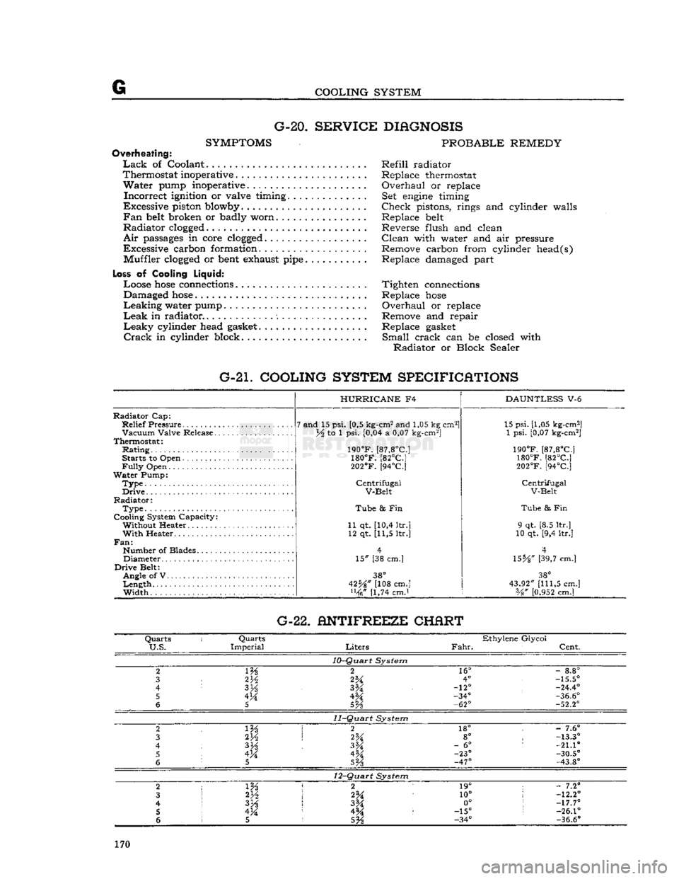
COOLING SYSTEM G-20.
SERVICE DIAGNOSIS
SYMPTOMS
PROBABLE REMEDY
Overheating:
Lack
of Coolant Refill radiator
Thermostat inoperative . Replace thermostat
Water
pump inoperative. Overhaul or replace
Incorrect
ignition or valve timing. Set
engine
timing
Excessive piston blowby Check pistons, rings and cylinder walls
Fan
belt
broken or badly worn Replace
belt
Radiator
clogged
Reverse flush and clean
Air
passages
in core
clogged
Clean with water and air pressure
Excessive carbon formation. Remove carbon from cylinder head(s) Muffler
clogged
or
bent
exhaust
pipe
Replace damaged part
Loss
of Cooling
Liquid:
Loose
hose
connections
Tighten
connections
Damaged
hose
Replace
hose
Leaking
water pump Overhaul or replace
Leak
in radiator Remove and repair
Leaky
cylinder head
gasket
Replace
gasket
Crack
in cylinder block. Small crack can be closed with
Radiator
or Block Sealer
G-21. COOLING SYSTEM SPECIFICATIONS
Radiator
Cap:
Relief
Pressure
Vacuum
Valve Release.
Thermostat:
Rating
Starts to Open
Fully
Open
Water
Pump:
Type.
Drive
Radiator:
Type
Cooling System Capacity: Without Heater
With
Heater..
Fan:
Number of Blades Diameter
Drive
Belt: Angle of V
Length
Width
HURRICANE
F4
7 and 15 psi. [0,5 kg-cm2 and 1,05 kg cm2]
lA to 1 psi. [0,04 a 0,07 kg-cm2]
190°F.
[87,8°C]
180°F.
[82°C]
202°F.
[94°C]
Centrifugal
V-Belt
Tube
8s Fin
11 qt. [10,4 ltr.] 12 qt. [11,5 ltr.]
15" [38 cm.]
38°
42%" [108 cm.] [1,74 cmJ
DAUNTLESS
V-6 15 psi. [1,05 kg-cm2]
1 psi. [0,07 kg-cm2]
190°F.
[87,8°C]
180°F.
[82°C]
202°F.
[94°C]
Centrifugal
V-Belt
Tube
& Fin
9 qt. [8.5 ltr.]
10 qt. [9,4 ltr.]
4
\SbA"
[39,7 cm.]
38°
43.92"
[111,5
cm.] Vg"
[0.952
cm.] G-22. ANTIFREEZE CHERT
Quarts
i
Quarts
Ethylene Glycol
U.S.
Imperial
Liters
Fahr.
Cent.
10-Quart
System
2
m
2
16°
-
8.8°
3
2V2
2%
4°
-15.5°
4
3H
-12°
-24.4°
5 4M -34°
-36.6°
6
5
5Vs
-62°
-52.2°
11-Quart
System
2 2
18° -
7.6°
3 2H
2%
8°
-13.3°
4
3%
-
6°
:
-21.10
5 4M 4M -23°
-30.5°
6
5
SVs
-47°
-43.8°
12-Quart
System
2
1 m 2 1
19° ;
- 7.2°
3
2*A
10°
!
-12.2°
4
I
3H
3M 0°
;
-17.7°
5 !
4M 4^ :
-15°
s
-26.1°
6 1 5
5%
-34°
-36.6°
170
Page 171 of 376
'Jeep'
UNIVERSAL SERIES SERVICE
MANUAL
H
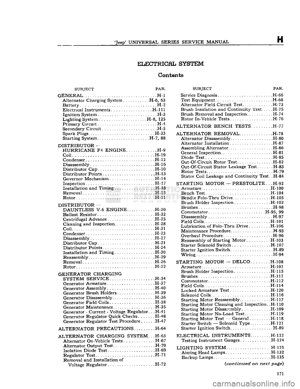
ELECTRICAL
SYSTEM
Contents
SUBJECT
PAR.
GENERAL
. -H-l Alternator Charging System H-6, 63 Battery. . . .H-2
Electrical
Instruments. H-l 11 Ignition System H-3
Lighting
System H-8, 125
Primary
Circuit.
.. H-4 Secondary
Circuit
H-5
SparkPlugs H-33
Starting System H-7, 88
DISTRIBUTOR
—
HURRICANE
F4
ENGINE
H-9
Coil
H-19 Condenser
.H-l
2
Disassembly.
.........................
.H-16
Distributor Cap H-10 Distributor
Points
H-13
Governor Mechanism H-l4
Inspection H-l
7
Installation and Timing H-18
Removal H-15
Rotor H-ll
DISTRIBUTOR
—
DAUNTLESS
V-6
ENGINE
H-20
Ballast
Resistor. H-32
Centrifugal
Advance H-25
Cleaning and Inspection H-28
Coil
H-31
Condenser H-23
Disassembly. H-27
Distributor Cap H-21 Distributor
Points
H-24
Installation and Timing. . .H-30
Reassembly. H-29
Removal H-2 6
Rotor H-2
2
GENERATOR CHARGING SYSTEM SERVICE
H-34 Generator Armature H-3
7
Generator Assembly. H-40
Generator
Brush
Holders H-39
Generator Disassembly H-36
Generator
Field
Coils.
H-38
Generator Maintenance H-35 Generator -
Current
-
Voltage
Regulator. . .H-41
Generator Regulator Quick Checks...... .H-48
Generator Regulator Test Procedure H-47
ALTERNATOR PRECAUTIONS.
H-64
ALTERNATOR CHARGING SYSTEM.
. .H-63 Alternator On-Vehicle Tests. .H-67
Alternator Output Test. .H-70 Isolation
Diode
Test H-69
Regulator Test .H-71 Removal and Installation of
Voltage
Regulator. H-72
SUBJECT
PAR.
Service
Diagnosis
H-66 Test Equipment H-68
Alternator
Field
Circuit
Test H-73
Brush
Insulation and Continuity Test H-75
Brush
Removal and Inspection H-74
Rotor In-Vehicle Tests H-76
ALTERNATOR BENCH TESTS.
.H-77
ALTERNATOR REMOVAL
H-78 Alternator Disassembly H-80 Alternator Installation. H-87
Assembling Alternator H-86
General
Inspection H-81
Diode
Test H-85
Out-Of-Circuit
Rotor Test. .H-82
Out-Of-Circuit
Stator Leakage Test.. . H-83 Rotor Tests H-79
Stator
Coil
Leakage and Continuity Test. .H-84
STARTING
MOTOR
—
PRESTOLITE.
. .H-92
Armature
.H-l
00 Bench Test H-l04
Bendix
Folo-Thru
Drive H-105
Brush
Holder Inspection. .H-102
Brushes H-98
Commutator H-95, 99
Disassembly H-9 7
Field
Coils H-101
Lubrication
of
Folo-Thru
Drive H-l06
Maintenance Procedure H-93
Overhaul
Procedure H-96
Reassembly of Starting Motor. .
H-l
03
Starter
Solenoid
Switch H-10 7 Starter Ignition Switch. .H-89
Wiring.
. . . H-94
STARTING
MOTOR
—DELCO
H-108
Armature
H-101
Brush
Holder Inspection H-l 15 Brushes
H:lll
Commutator H-112
Field
Coils........
H-114
Locked
Armature Test. . . H-l20
Solenoid
Coils H-l 16
Starting Motor Reassembly H-l 17
Starting Motor Cleaning and Inspection.
.H-l
10
Starting Motor Disassembly .H-109 Starting Motor No-Load Test H-119
Starting Motor Test — General H-l 18 Starter Switch —
Solenoid
Type. H-l21
Starter Ignition Switch. .H-89
ELECTRICAL
INSTRUMENTS
H-122 Testing Instrument Gauges H-l24
LIGHTING
SYSTEM
H-l25 Aiming Head Lamps H-132
Backup
Lamps H-135
(continued
on
next
page)
171