engine JEEP CJ 1953 Service Manual
[x] Cancel search | Manufacturer: JEEP, Model Year: 1953, Model line: CJ, Model: JEEP CJ 1953Pages: 376, PDF Size: 19.96 MB
Page 150 of 376
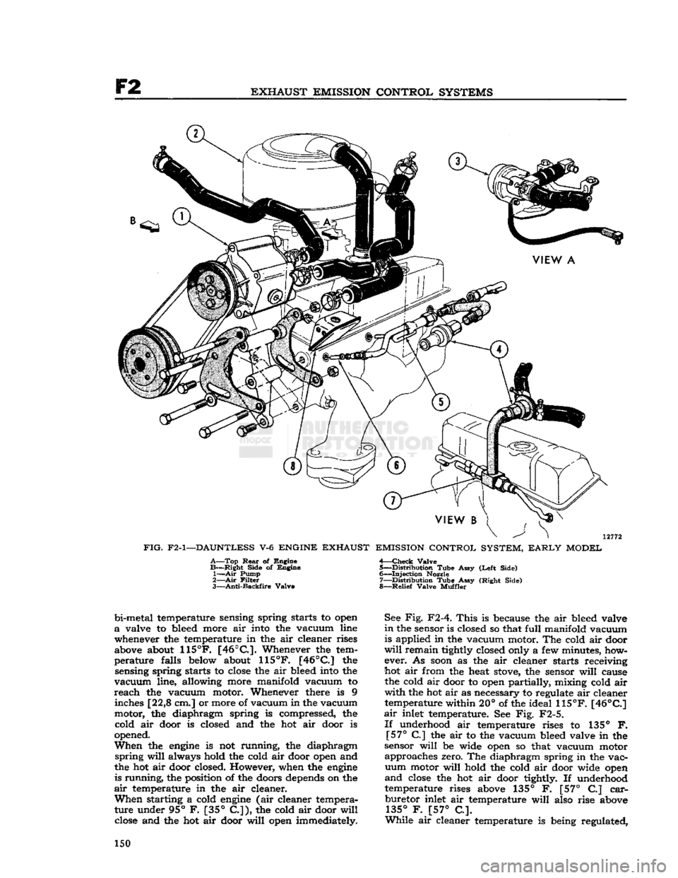
EXHAUST
EMISSION
CONTROL
SYSTEMS
bi-metal temperature sensing spring starts to open
a
valve to bleed more air into the vacuum line
whenever the temperature in the air cleaner rises
above about
115°F.
[46°C.].
Whenever the tem
perature
falls below about
115°F.
[46°C]
the sensing spring starts to
close
the air bleed into the
vacuum
line, allowing more manifold vacuum to
reach
the vacuum motor. Whenever there is 9 inches [22,8 cm.] or more of vacuum in the vacuum
motor, the diaphragm spring is compressed, the cold air door is closed and the hot air door is
opened.
When
the
engine
is not running, the diaphragm
spring
will
always hold the cold air door open and
the hot air door closed. However, when the
engine
is running, the position of the doors depends on the
air
temperature in the air cleaner.
When
starting a cold
engine
(air cleaner tempera
ture under 95° F. [35°
C.]),
the cold air door
will
close
and the hot air door
will
open immediately. See Fig. F2-4.
This
is because the air bleed valve
in
the sensor is closed so that
full
manifold vacuum
is applied in the vacuum motor. The cold air door
will
remain tightly closed only a few minutes, how
ever. As
soon
as the air cleaner starts receiving
hot air from the heat
stove,
the sensor
will
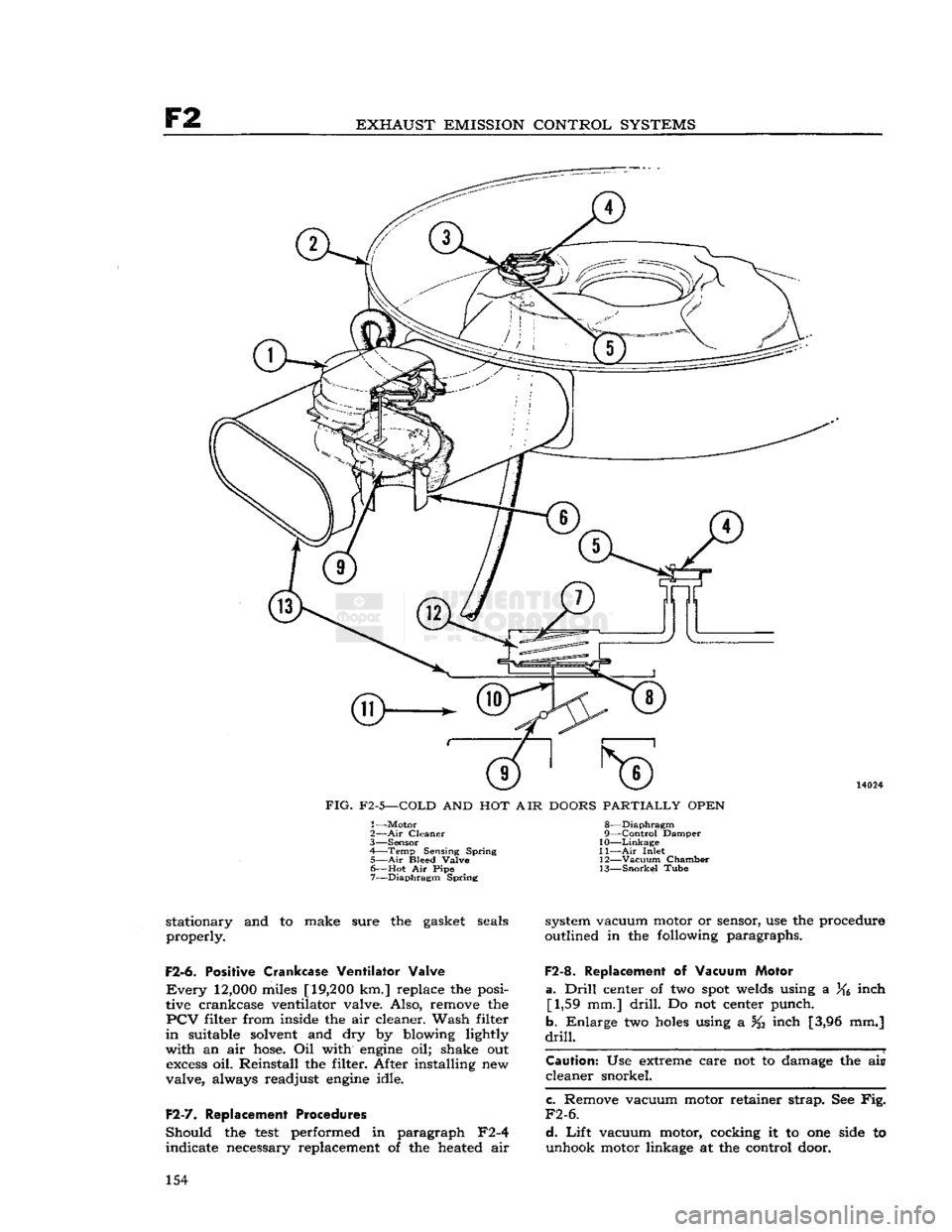
cause the cold air door to open partially, mixing cold air
with
the hot air as necessary to regulate air cleaner temperature within 20° of the ideal
115°F.
[46°C]
air
inlet temperature. See Fig. F2-5.
If
underhood air temperature rises to 135° F.
[57°
C] the air to the vacuum bleed valve in the
sensor
will
be wide open so that vacuum motor approaches zero. The diaphragm spring in the vac
uum
motor
will
hold the cold air door wide open
and
close
the hot air door tightly. If underhood
temperature rises above 135° F. [57° C]
car
buretor inlet air temperature
will
also rise above
135°
F. [57° C.].
While
air cleaner temperature is being regulated, 150
Page 151 of 376
'Jeep*
UNIVERSAL
SERIES
SERVICE
MANUAL
F2
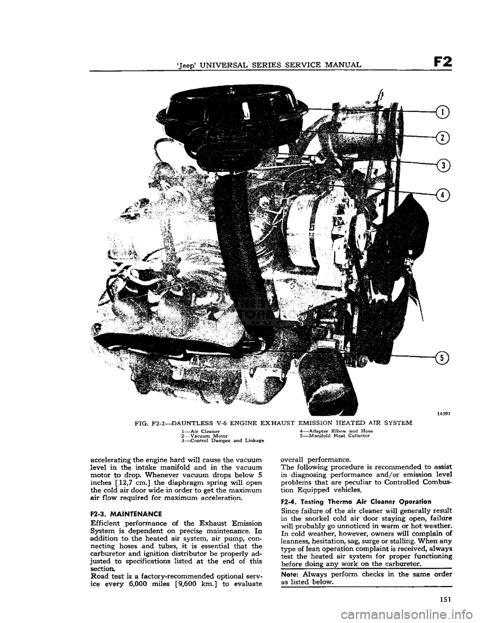
FIG.
F2-2—DAUNTLESS
V-6
ENGINE
EXHAUST
EMISSION
HEATED
AIR
SYSTEM
1—
Air
Cleaner 4—Adapter
Elbow
and Hose
2—
Vacuum
Motor 5—Manifold Heat Collector
3—
Control
Damper and
Linkage
accelerating the
engine
hard
will
cause the vacuum
level in the intake manifold and in the vacuum motor to drop. Whenever vacuum drops
below
5 inches [12,7 cm.] the diaphragm spring
will
open
the cold air door wide in order to get the maximum
air
flow required for maximum acceleration.
F2-3.
MAINTENANCE
Efficient
performance of the
Exhaust
Emission
System is
dependent
on precise maintenance. In
addition to the heated air system, air pump, con necting
hoses
and tubes, it is essential that the
carburetor
and ignition distributor be properly ad
justed to specifications listed at the end of this section.
Road
test
is a factory-recommended optional serv
ice every
6,000
miles
[9,600
km.] to evaluate
overall
performance.
The
following procedure is recommended to assist
in
diagnosing performance and/or emission level problems that are peculiar to Controlled Combus
tion Equipped vehicles.
F2-4.
Testing Thermo
Air
Cleaner Operation
Since
failure of the air cleaner
will
generally result
in
the snorkel cold air door staying open, failure
will
probably go unnoticed in warm or hot weather.
In
cold weather, however, owners
will
complain of
leanness, hesitation, sag, surge or stalling. When any
type
of lean operation complaint is received, always
test
the heated air system for proper functioning
before
doing any work on the carburetor.
Note:
Always perform checks in the same order
as listed
below.
151
Page 152 of 376
F2
EXHAUST EMISSION CONTROL SYSTEMS
<3>
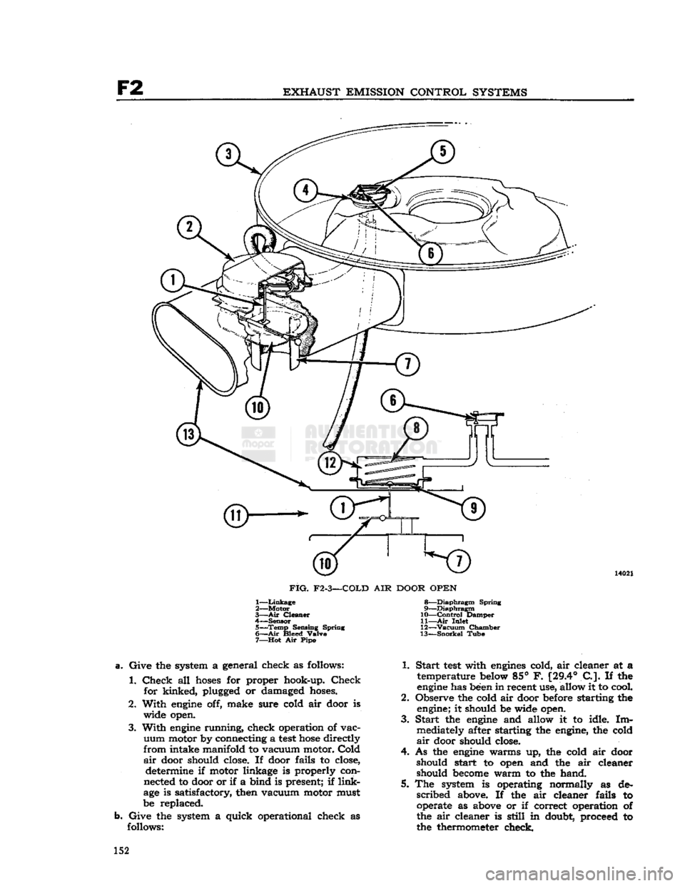
FIG.
F2-3—COLD
AIR
DOOR OPEN
1—
Linkage
2— Motor
3— Air
Cleaner
4—
Sensor
5—
Temp
Sensing Spring
6—
Air
Bleed Valve
7—
Hot
Air
Pip®
8—
Diaphragm
Spring
9—
Diaphragm
10—
Control
Damper
11—
Air
Inlet
12—
Vacuum
Chamber
13—
Snorkel
Tube
Give
the
system
a
general check
as
follows:
1.
Check
all
hoses
for
proper hook-up.
Check
for kinked, plugged
or
damaged
hoses.
2. With
engine
off,
make sure cold
air
door
is
wide open.
3.
With
engine
running, check operation
of
vac
uum
motor by connecting
a
test
hose
directly
from
intake manifold
to
vacuum motor.
Cold
air
door should close.
If
door fails
to
close, determine
if
motor linkage
is
properly con
nected
to
door or
if a
bind
is
present;
if
link
age
is
satisfactory, then vacuum motor must
be replaced.
Give
the
system
a
quick operational check
as
follows: 1. Start
test
with
engines
cold, air cleaner
at a
temperature below 85°
F.
[29.4°
C.].
If the
engine
has been in recent use, allow
it to
cool.
2. Observe
the
cold air door before starting
the
engine;
it
should
be
wide open.
3.
Start
the
engine
and
allow
it to
idle.
Im
mediately after starting
the
engine,
the
cold
air
door should close.
4.
As the
engine
warms
up, the
cold
air
door should start
to
open
and the air
cleaner should
become
warm
to the
hand.
5.
The
system
is
operating normally
as de
scribed
above.
If the air
cleaner fails
to
operate
as
above
or if
correct operation
of
the
air
cleaner
is
still
in
doubt, proceed
to
the thermometer check. 152
Page 153 of 376
'Jeep'
UNIVERSAL
SERIES SERVICE
MANUAL
F2
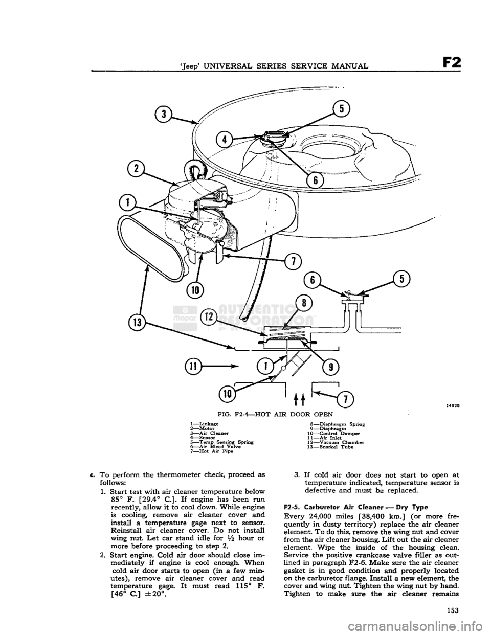
FIG.
F2-4—HOT
AIR
DOOR
OPEN
1—
Linkage
2— Motor
3—
Air
Cleaner
4— Sensor 5—
Temp
Sensing Spring
6—
Air
Bleed Valve 7—
Hot
Air Pipe 8—
Diaphragm
Spring
9—
Diaphragm
10—
Control
Damper
11—
Air
Inlet
12—
Vacuum
Chamber
13—
Snorkel
Tube
To
perform the thermometer check, proceed as
follows:
1. Start
test
with air cleaner temperature below
85°
F.
[29.4°
C.]. If
engine
has been run recently, allow it to cool down. While
engine
is cooling, remove air cleaner cover and
install
a temperature
gage
next to sensor.
Reinstall
air cleaner cover. Do not install wing nut. Let car stand idle for
V2
hour or
more before proceeding to
step
2.
2. Start engine.
Cold
air door should
close
im mediately if
engine
is cool enough. When cold air door starts to open (in a few min
utes), remove air cleaner cover and read
temperature
gage.
It must read 115° F.
[46°
C]
±20°.
3.
If cold air door
does
not start to open at
temperature indicated, temperature sensor is
defective and must be replaced.
F2-5.
Carburetor Air
Cleaner—Dry
Type
Every
24,000
miles
[38,400
km.] (or more fre
quently in dusty territory) replace the air cleaner element. To do this, remove the wing nut and cover
from
the air cleaner housing.
Lift
out the air cleaner
element. Wipe the inside of the housing clean.
Service
the positive crankcase valve filler as out
lined in paragraph F2-6. Make sure the air cleaner gasket is in
good
condition and properly located
on the carburetor flange.
Install
a new element, the cover and wing nut. Tighten the wing nut by hand.
Tighten
to make sure the air cleaner remains 153
Page 154 of 376
F2
EXHAUST
EMISSION
CONTROL
SYSTEMS
FIG.
F2-5—COLD
AND
HOT AIR
DOORS
PARTIALLY
OPEN
1— Motor
2—
Air
Cleaner
3—
Sensor
4—
Temp
Sensing Spring 5—
Air
Bleed Valve
6— Hot
Air
Pipe
7—
Diaphragm
Spring 8—
Diaphragm
9—
Control
Damper
10—
Linkage
11—
Air
Inlet 12—
Vacuum
Chamber
13—
Snorkel
Tube stationary
and to
make sure
the
gasket seals
properly. system vacuum motor
or
sensor,
use the
procedure
outlined
in the
following paragraphs.
F2-6.
Positive Crankcase Ventilator Valve
Every
12,000
miles
[19,200
km.] replace
the
posi
tive crankcase ventilator valve. Also, remove
the
PCV
filter from inside
the air
cleaner. Wash filter
in
suitable solvent
and dry by
blowing lightly
with
an air
hose.
Oil
with
engine
oil;
shake
out
excess
oil.
Reinstall
the
filter. After installing
new
valve, always readjust
engine
idle.
F2-7.
Replacement Procedures
Should
the
test
performed
in
paragraph
F2-4
indicate necessary replacement
of the
heated
air
F2-8.
Replacement of
Vacuum Motor
a.
Drill
center
of two
spot
welds using
a ]f6
inch [1,59
mm.]
drill.
Do not
center punch.
b. Enlarge
two
holes
using
a
j& inch
[3,96 mm.]
drill.
Caution:
Use
extreme care
not to
damage
the ail
cleaner snorkel.
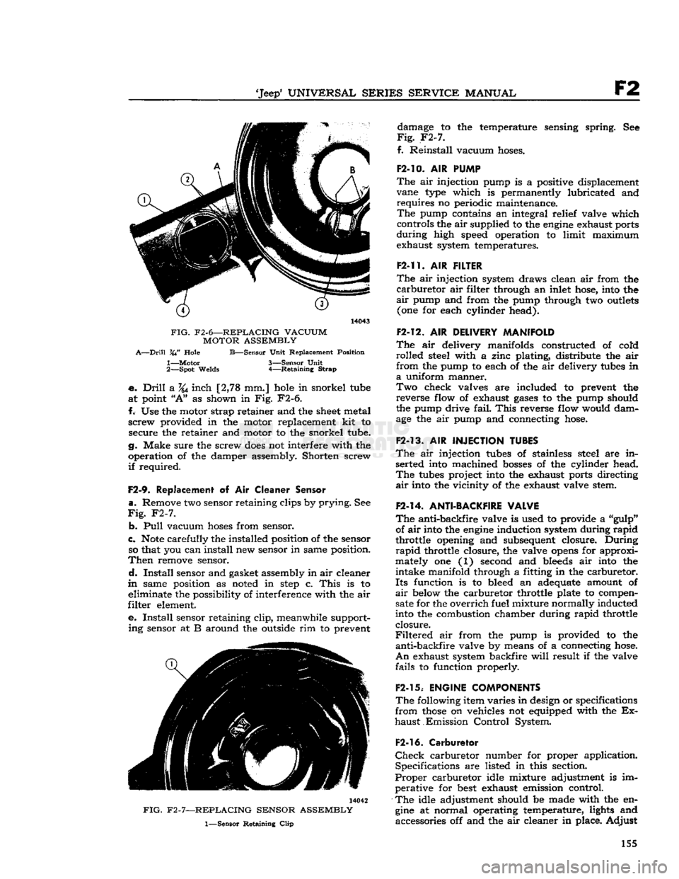
c. Remove vacuum motor retainer strap.
See
Fig.
F2-6.
d.
Lift
vacuum motor, cocking
it to one
side
to
unhook motor linkage
at the
control door. 154
Page 155 of 376
'Jeep'
UNIVERSAL
SERIES
SERVICE
MANUAL
F2
14043
FIG.
F2-6—REPLACING VACUUM MOTOR ASSEMBLY
A—Drill
VW
Hole
B—Sensor
Unit
Replacement Position
1—
Motor
3—Sensor
Unit
2—
Spot
Welds
4—Retaining
Strap
•e.
Drill
a
%j
inch [2,78 mm.] hole in snorkel tube
at
point
"A"
as shown in Fig.
F2-6.
f.
Use the motor strap retainer and the
sheet
metal
screw
provided in the motor replacement kit to secure the retainer and motor to the snorkel tube.
g. Make sure the screw
does
not interfere with the
operation of the damper assembly. Shorten screw
if
required.
F2-9.
Replacement
of Air
Cleaner Sensor
a.
Remove two sensor retaining clips by
prying.
See
Fig.
F2-7.
b.
Pull
vacuum
hoses
from sensor.
c.
Note
carefully the installed position of the sensor so that you can install new sensor in same position.
Then
remove sensor.
d.
Install
sensor and gasket assembly in air cleaner
m
same position as noted in
step
c.
This
is to eliminate the possibility of interference with the air
filter
element.
e.
Install
sensor retaining
clip,
meanwhile support
ing
sensor at B around the outside rim to prevent 14042
FIG.
F2-7—REPLACING SENSOR ASSEMBLY
1—Sensor
Retaining
Clip
damage to the temperature sensing spring. See
Fig.
F2-7.
f.
Reinstall
vacuum hoses.
F2-10.
AIR
PUMP
The
air injection pump is a positive displacement
vane type which is permanently lubricated and
requires
no periodic maintenance.
The
pump contains an integral relief valve which
controls the
air
supplied to the
engine
exhaust ports
during
high speed operation to limit maximum exhaust system temperatures.
F2-11.
AIR
FILTER
The
air injection system draws clean air from the
carburetor
air filter through an inlet hose, into the
air
pump and from the pump through two
outlets
(one for each cylinder head).
F2-12.
AIR
DELIVERY MANIFOLD
The
air delivery manifolds constructed of cold
rolled
steel with a zinc plating, distribute the air
from
the pump to each of the air delivery tubes in
a
uniform manner.
Two
check valves are included to prevent the
reverse
flow of exhaust
gases
to the pump should
the pump drive
fail.
This
reverse flow would dam
age the air pump and connecting hose.
F2-13.
AIR
INJECTION TUBES
The
air injection tubes of stainless steel are in serted into machined
bosses
of the cylinder head.
The
tubes project into the exhaust ports directing
air
into the vicinity of the exhaust valve stem.
F2-14.
ANTI-BACKFIRE VALVE
The
anti-backfire valve is used to provide a "gulp" of air into the
engine
induction system during
rapid
throttle opening and subsequent closure.
During
rapid
throttle closure, the valve
opens
for approxi
mately one (1) second and bleeds air into the
intake
manifold through a fitting in the carburetor.
Its
function is to bleed an adequate amount of
air
below the carburetor throttle plate to compen sate for the
overrich
fuel mixture normally inducted
into the combustion chamber during
rapid
throttle
closure.
Filtered
air from the pump is provided to the
anti-backfire
valve by means of a connecting hose.
An
exhaust system backfire
will
result if the valve
fails
to function properly.
F2-15.
ENGINE COMPONENTS
The
following item varies in design or specifications
from
those
on vehicles not equipped with the Ex
haust
Emission
Control
System.
F2-16.
Carburetor
Check
carburetor number for proper application. Specifications are listed in this section.
Proper
carburetor idle mixture adjustment is im perative for
best
exhaust emission control.
The
idle adjustment should be made with the en
gine
at normal operating temperature, lights and accessories off and the air cleaner in place.
Adjust
155
Page 156 of 376
F2
EXHAUST EMISSION CONTROL SYSTEMS
the throttle
stop
screw to idle the
engine
at 650
to 700 rpm.
F2-17. Carburetor Idle Setting
The
"Lean
Best
Idle"
Method of Idle Setting is as
follows:
a.
Any scheduled service of ignition system should
precede this adjustment
b.
Connect tachometer to engine.
c.
Warm
up
engine
and stabilize temperatures.
d.
Adjust
engine
idle to speed desired, using throt
tle idle speed adjusting screw.
e.
Turn
idle mixture screws out (counterclockwise)
until
a
loss
of
engine
speed is indicated; then slowly
turn
mixture screws in (clockwise-leaner)
until
maximum speed (rpm) is reached. Continue
turning
in (clockwise) until speed begins to drop;
turn
mixture adjustment back out (counterclock
wise-richer)
until maximum speed is just regained
at
a "lean as possible" mixture adjustment.
F2-18. Distributor
The
ignition distributor used with the
Exhaust
Emission
Control
System is the same as that used
on
engines
without
Exhaust
Emission
Control.
Check
the distributor cam dwell angle and point
condition.
Check
ignition timing and adjust to specifications shown on the last
page
of this section.
F2-19.
Anti-Backfire
Valve
The
anti-backfire valve remains closed except when
the throttle is closed rapidly from an open position.
To
check the valve for proper operation, accelerate
the
engine
in neutral, allowing the throttle to close
rapidly.
The valve is operating satisfactorily when
no exhaust system backfire occurs. A further check
to determine whether the valve is functioning can
be made by removing from the anti-backfire valve
the large
hose
which connects the valve to the
pump.
With
a finger placed over the open end of
the
hose
(not the valve), accelerate the
engine
and allow the throttle to close rapidly. The valve is
operating satisfactorily if a momentary air rushing
noise is audible.
F2-20.
Check
Valve
The
check valves in the lines to the air distribution manifolds prevent the reverse flow of exhaust
gases
to the pump in the event the pump should, for
any
reason,
become
inoperative or should exhaust
pressure
ever exceed pump pressure.
To
check this valve for proper operation, remove the air supply
hose
from the pump at the check
valve.
With
the
engine
running, listen for exhaust
leakage at the check valve which is connected to
the distribution manifold.
F2-21.
Air
Pump
Check
for proper drive belt tension with belt tension
gauge
W-283. The belt strand tension should be 60 pounds measured on the
longest
accessible span
between two pulleys. DO NOT PRY ON THE
DIE
CAST
PUMP
HOUSING. To
check the pump for proper operation, remove
the air
outlet
hose
at the pump.
With
the
engine
running,
air discharge should be felt at one of
the pump
outlet
openings. The pump
outlet
air
pressure,
as determined by the relief valve, is preset
and
is not adjustable.
The
air pump
rear
cover assembly, housing the pressed in inlet and discharge tubes, and the pres
sure
relief valve are the only pump components
recommended for service replacement. These parts
are
to be replaced only when damaged as a result
of handling or in the event the relief valve was
tampered with.
F2-22.
Intake Manifold
Intake
manifold leaks must not be overlooked. Air
leakage at the intake manifold may be compen
sated for by
richer
idle mixture setting, however, this
will
usually cause uneven fuel-air distribution
and
will
always result in
loss
of performance and
exhaust emission control. To check for air leakage
into the intake manifold, apply kerosene or naph
tha,
on the intake manifold to cylinder head joints
and
observe whether any changes in
engine
rpm
occur.
If an air leak is indicated, check the mani
fold to cylinder head bolt torque. The correct torque is 25-35 lbs. ft. [3,46 a 4,84 kg-m.]. If the
leak
is
still
evident,
loosen
the manifold assembly
and
torque-tighten the bolts evenly.
Start
from the center and use proper torque values. Replace the
manifold
gasket if the leak
still
exists.
Clean
both
mating surfaces and check for
burrs
or other ir
regularities.
Always
torque the bolts evenly to the specified
torque value to prevent warpage.
F2-23.
Carburetor
Air
Cleaner
—Oil
Bath
Every
6,000
miles [9,600 km.] disconnect attach
ing
hoses
and unscrew the wing nut from the top
of the air cleaner and lift it off the carburetor.
Lift
the cover and filter element off the oil sump.
Clean
the inside surface of the sump and
refill
to
indicated
oil level with SAE 40 or 50
engine
oil
above 32 F; SAE 20 below 32 F.
Wash
filter element in kerosene and
drain.
Reassemble the air
cleaner
and install on carburetor.
More
frequent cleaning and replacement are advis able when the car is operated in dusty areas or on
unpaved
roads. Accumulated
dirt
restricts air flow,
reducing
fuel economy and performance.
F2-24.
REMOVAL PROCEDURES
The
following paragraphs
give
the procedures for removing the major units of the exhaust emission
control
system and the required equipment needed.
F2-2S.
Air
Pump
Loosen
the air pump mounting bracket bolts. Re move the air pump air hose(s). Separate the air pump from its mounting bracket. At time of install
ation,
torque tighten the air pump mounting bolts
to
30-40
lbs.-ft [4,15 a 5,53 kg-m.].
Adjust
the
belt strand tension to 60 pounds. 156
Page 157 of 376
'Jeep'
UNIVERSAL
SERIES SERVICE
MANUAL
F2
F2-26.
Anti-Backfire
Valve
The
anti-backfire valve removal requires discon necting the
hoses
and bracket to
engine
attaching
screws.
F2-27.
Air Distribution Manifold and
Injection
Tubes
The
air distribution manifolds can be removed
from the cylinder heads without removing the
cylinder
head assemblies. Disconnect the air delivery
hose
from the pump at
the distribution manifold inlet (check valve).
Loosen the distribution manifold
tube
attaching nuts from the cylinder head and carefully work the
distribution manifold away from the cylinder head.
The
air injection
tubes
can be removed from the
cylinder
head with head on the
engine.
Insert
an easy-out through the
boss
opening on the
cylinder
head
into
the injection
tube
and twist
the
tube
out gradually. Some interference to re moval may be encountered due to normal carbon
build-up on the tubes. Injection
tubes
removed in
this manner should be replaced.
The
injection
tubes
used are all of the same diam
eter and length.
F2-28.
REQUIRED EQUIPMENT
Each
station licensed to perform repair and main tenance on the Exhaust Emission Control System
must be equipped with that equipment necessary
for major
engine
tune-up analysis which shall in clude at least the following or equivalent:
Ignition Analyzer Oscilloscope
Ammeter
Ohmmeter
Voltmeter
Tachometer 2 Vacuum Gauges
Pressure
Gauge (0-10 psi.)
Cam
Angle Dwell Meter
Ignition Timing
Light
Engine
Exhaust Combustion Analyzer Compression Tester
F2-29.
REPLACEMENT PARTS
Parts
necessary to repair and/or maintain the Ex
haust Emission Control System are available through any Jeep
SALES
CORPORATION
ware
house.
F2-30.
WARRANTY
All
parts of the Exhaust Emission Control System
are
covered by the Manufacturer's
Warranty
as stated in the
Warranty
Service and 'Jeep' Quality
Maintenance Plan booklet. 157
Page 158 of 376
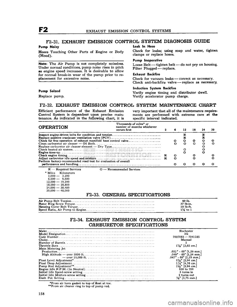
F2
EXHAUST EMISSION CONTROL SYSTEMS
F2-3L
EXHAUST EMISSION CONTROL SYSTEM
DIAGNOSIS
GUIDE
Pump Noisy
Hoses Touching Other Parts of Engine or Body (Hood).
Note:
The Air Pump is not completely noiseless.
Under
normal conditions, pump
noise
rises in pitch as
engine
speed
increases. It is desirable to allow
for normal break-in wear of the pump prior to re
placement for
excessive
noise.
Pump Seized
Replace pump.
-
do not pry on housing.
Leak
In Hose
Check
for leaks; using
soap
and water, tighten clamps or replace
hoses.
Pump Inoperative
Loose Belt — tighten belt
-
Filter
Plugged — replace.
Exhaust
Backfire
Check
for vacuum leaks — correct as necessary.
Check
anti-backfire valve — replace as necessary
Induction System Backfire
Verify
engine
timing and distributor dwell.
Verify
accelerator pump charge.
F2-32.
EXHAUST EMISSION CONTROL SYSTEM MAINTENANCE CHART
Efficient
performance of the Exhaust Emission very important that all of the maintenance require-
Control
System is
dependent
upon precise main-
ments
are performed with extreme care at the
tenance. As indicated in the following chart, it is specific interval indicated.
Thousands of miles* or
OPERATION
number of months whichever occurs first 2 6 12 18 24 30
Inspect engine-driven
belts
for condition and tension R R
Replace positive crankcase ventilation valve
(PCV)
R R
Check
for free operation of exhaust manifold heat control valve O O O O O
Clean
carburetor air cleaner — Oil Bath O O O O O
Replace carburetor air cleaner
element
— Dry Type O
Check
heated air system O O
Engine
tune-up O O
Check
engine
timing R O O O
Adjust
carburetor idle
speed
and mixture R O O O
Perform
factory-recommended road
test
for evaluation of overall performance and handling O O O O O
R
— Required Services O — Recommended Services
*
Miles Kilometers
2,000
—
3,200
6,000
—
9,600
12,000
—
19,200 18,000
—
28,800
24,000
—
38,400
30,000
—
48,000
F2-33.
GENERAL SPECIFICATIONS
Air
Pump Belt Tension 60 lb.
Rotor
Ring Screw Torque . 37 lb-in.
Housing Cover Bolt Torque 10 lb-ft. Speed Ratio, Air Pump to Engine
1
\i to 1
F2-34.
EXHAUST EMISSION CONTROL SYSTEM CARBURETOR SPECIFICATIONS
Make
Rochester Model Designation 2G Code Number
7027082
—
7041185
Choke
Manual
Number of Barrels 2
Throttle
Bore... \W [3,65 cm.]
Main
Metering Jet Production .051" - 60° [1,29 mm.]
High
Altitude — over
5000
ft .049" - 60° [1,24 mm.]
—
over
10,000
ft .047" - 60° [1,19 mm.]
Float
Level
Adjustment* 1%," [2,94 cm.]
Float
Drop Adjustment l%" [4,76 cm.]
Pump Rod Adjustment** 1%" [2,94 cm.]
Engine
Idle
R.P.M.
(In Neutral) 650 to 700
Initial
Idle Speed-screw
setting
3 turns in
Initial
Idle Mixture-screw
setting
2 turns out
Dash
Pot Setting. Y%w [3,75 mm.]
*From
air horn gasket to top of float at toe.
**From
air cleaner ring to top of pump rod.
158
Page 159 of 376
'Jeep'
UNIVERSAL SERIES SERVICE
MANUAL
F2
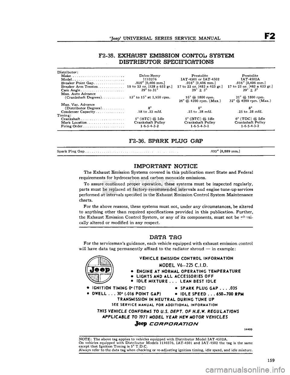
F2-35.
EXHAUST EMISSION CONTOL SYSTEM
DISTRIBUTOR SPECIFICATIONS
Distributor:
Make
Delco-Remy Prestolite Prestolite
Model...
1110376
IAT-4501 or IAT-4502 IAT-4502A
Breaker
Point Gap .016"
[0,406
mm.] .016"
[0,406
mm.] .016"
[0,406
mm.]
Breaker
Arm Tension 19 to 23 oz. [538 a 652 gr.] 17 to 22 oz. [482 a 623 gr.] 17 to 22 oz. [482 a 623 gr.]
Cam
Angle. 29° to 31° 29° + 3° 29° ± 3°
Max.
Auto Advance
(Crankshaft
Degrees). 13° to 15° at 1,950 rpm. 16° (& 1800 rpm. 21° @ 1800 rpm.
26°
@
4200
rpm. (Max.) 32° @
4200
rpm. (Max.)
Max.
Vac. Advance
(Distributor
Degrees) 8° 8° 8°
Condenser Capacity. .18 to .23 mfd. .25 to .28 mfd. .25 to .28 mfd.
Timing:
Crankshaft
5°
(BTC)
@ Idle 5°
(BTC)
© Idle 0°
(TDC)
© Idle
Mark
Location Crankshaft Pulley Crankshaft Pulley Crankshaft Pulley
Firing
Order
1-6-5-4-3-2 1-6-5-4-3-2 1-6-5-4-3-2
F2-36.
SPARK PLUG
GAP
Spark
Plug Gap. .035"
[0,889
mm.]
IMPORTANT
NOTICE
The
Exhaust Emission Systems covered in this publication
meet
State and Federal
requirements for hydrocarbon and carbon
monoxide
emissions.
To
assure continued proper operation,
these
systems
must be inspected regularly,
parts must be replaced at factory-recommended intervals and
engine
tune-up services
performed at intervals specified in the Exhaust Emission Control System Maintenance
charts.
For
the
above
reasons,
these
systems
must not, under any circumstances, be altered
to anything other than required specifications provided in this publication.
Further,
the Exhaust Emission Control System, or any of its components, must not be physi
cally
altered or modified in any respect.
DATA
TAG
For
the serviceman's guidance, each vehicle equipped with exhaust emission control
will
have data tag permanently affixed to the radiator shroud — in example:
VEHICLE EMISSION CONTROL INFORMATION MODEL V6-225 C.I.D.
•
ENGINE
AT
NORMAL OPERATING TEMPERATURE
•
LIGHTS
AND ALL
ACCESSORIES
OFF
•
IDLE MIXTURE
.. .
LEAN BEST IDLE
•
IGNITION TIMING
0*
(TDC)
*
SPARK PLUG
GAP 035
•
DWELL
. . . 30* (.016
POINT
GAP) •
IDLE SPEED
. . .
650- 700
RPM
TRANSMISSION
IN
NEUTRAL DURING TUNE
UP
SEE
SERVICE MANUAL FOR ADDITIONAL INFORMATION
THIS VEHICLE CONFORMS
TO U.S. DEPT. OF H.E.W.
REGULATIONS APPLICABLE
TO
1971
MODEL YEAR
NEW
MOTOR VEHICLES
Jeep
CORPORATION
14400
NOTE:
The
above
tag applies to vehicles equipped with Distributor Model
IAT-4502A.
On
vehicles equipped with Distributor Models
1110376,
IAT-4501 and IAT-4502 the tag is the same
except
that Ignition Timing is 5°
T.D.C.
Always
refer to the data tag when checking or re-adjusting ignition timing, idle speed, and idle mixture.
159