tow JEEP CJ 1953 Workshop Manual
[x] Cancel search | Manufacturer: JEEP, Model Year: 1953, Model line: CJ, Model: JEEP CJ 1953Pages: 376, PDF Size: 19.96 MB
Page 291 of 376
'Jeep*
UNIVERSAL
SERIES
SERVICE
MANUAL
N
N-6.
Lubricating
Unit Bearing
a.
After the bearing has been inspected and ap
proved for continued service, it must be
relubri-
cated
prior
to re-installation into the axle housing.
The
Unit Bearing assembly can be hand packed
with
grease on the axle shaft by the method out
lined
below.
Lithium
soap wheel bearing grease
Part
No.
998386
should be used to relubricate Unit
Bearing
assembly.
b.
Push seal away from bearing and
fill
the area
or
cavity
between
the seal and bearing with the recommended grease. Refer to Fig. N-9.
c.
After the cavity is
full
of grease, wrap tape completely around the rib ring and seal to
enclose
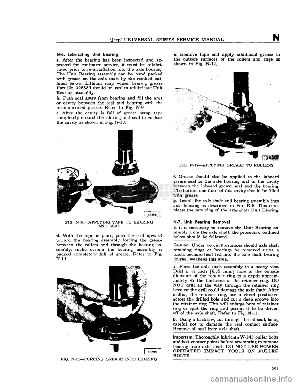
the cavity as shown in Fig. N-10.
FIG.
N-10—APPLYING
TAPE
TO
BEARING
AND
SEAL
d.
With
the tape in place, push the seal upward
toward
the bearing assembly forcing the grease
between
the rollers and through the bearing as
sembly, make certain the bearing assembly is
packed
completely
full
of grease. Refer to Fig.
N-ll.
FIG.
N-ll—FORCING
GREASE
INTO
BEARING
e. Remove tape and apply additional grease to
the outside surfaces of the rollers and
cage
as shown in Fig. N-l2.
FIG.
N-12—APPLYING
GREASE
TO
ROLLERS
ff.
Grease
should also be applied to the inboard
grease seal in the axle housing and in the cavity
between
the inboard grease seal and the bearing.
The
bottom
one-third of this cavity should be filled
with
grease.
g.
Install
the axle shaft and bearing assembly into axle housing as described in Par. N-8.
This
com
pletes
the servicing of the axle shaft Unit Bearing.
H-7.
Unit Bearing Removal
If
it is necessary to remove the Unit Bearing as
sembly from the axle shaft, the procedure outlined
below should be followed.
Caution:
Under no circumstances should axle shaft
retaining
rings or bearings be removed using a
torch,
because heat fed into the axle shaft bearing
journal
weakens this
area.
a.
Place the axle shaft assembly in a heavy vise.
Drill
a Vi inch [6,35 mm.]
hole
in the outside
diameter of the retainer ring to a depth approxi mately 3A the thickness of the retainer
ring.
DO
NOT
drill
all the way through the retainer ring because the
drill
could damage the axle shaft. After
drilling
the retainer
ring,
use a chisel positioned across the drilled
hole
and cut a
deep
groove
into
the retainer
ring.
This
will
enlarge bore of retainer
ring
or split the ring and permit it to be driven
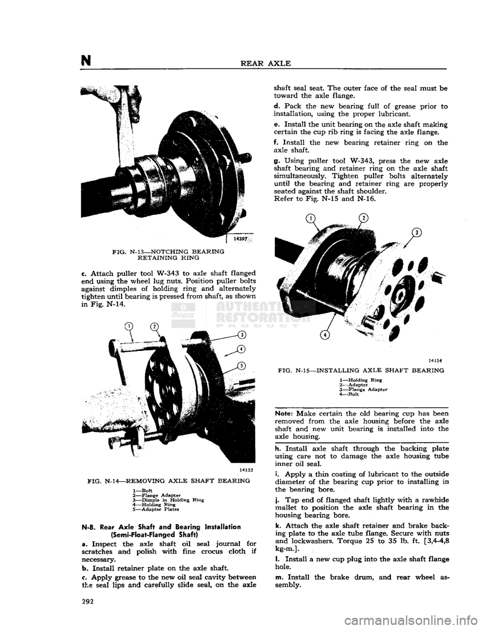
off of the axle shaft. Refer to Fig. N-13.
b.
Using a hacksaw, cut through the oil seal, being
careful
not to damage the seal contact surface.
Remove oil seal from axle shaft.
Important:
Thoroughly lubricate W-343 puller
bolts
and
bolt contact points before attempting to remove
bearing
from axle shaft DO NOT USE
POWER
OPERATED
IMPACT
TOOLS
ON
PULLER
BOLTS.
291
Page 292 of 376
N
REAR
AXLE
FIG.
N-l3—NOTCHING
BEARING
RETAINING
RING
c.
Attach puller
tool
W-343 to axle shaft flanged
end using the wheel lug nuts. Position puller
bolts
against dimples of holding ring and alternately tighten until bearing is pressed from shaft, as shown
in
Fig. N-14. 14152
FIG.
N-14—REMOVING
AXLE
SHAFT
BEARING
1—
Bolt
2—
Flange
Adapter
3—
Dimple
in Holding
Ring
4 Holding
Ring
5—
Adapter
Plates N-8.
Rear
Axle
Shaft and Bearing Installation
(Semi-Float-Flanged
Shaft)
a.
Inspect the axle shaft oil seal
journal
for
scratches and polish with fine crocus cloth if
necessary.
b.
Install
retainer plate on the axle shaft
c.
Apply grease to the new oil seal cavity
between
the seal lips and carefully slide seal, on the axle shaft seal seat. The outer face of the seal must be
toward
the axle flange.
d.
Pack
the new bearing
full
of grease
prior
to
installation,
using the proper lubricant.
e.
Install
the unit bearing on the axle shaft making
certain
the cup rib ring is facing the axle flange.
f.
Install
the new bearing retainer ring on the axle shaft.
g. Using puller
tool
W-343, press the new axle shaft bearing and retainer ring on the axle shaft
simultaneously. Tighten puller
bolts
alternately
until
the bearing and retainer ring are properly
seated
against the shaft shoulder.
Refer
to Fig. N-15 and N-16. 14154
FIG.
N-15—INSTALLING
AXLE
SHAFT
BEARING
1—
Holding
Ring
2—
Adapter
3—
Flange
Adapter
4—
Bolt
Note:
Make certain the old bearing cup has
been
removed from the axle housing
before
the axle
shaft and new unit bearing is installed
into
the
axle housing.
h.
Install
axle shaft through the backing plate
using care not to damage the axle housing
tube
inner
oil seal.
i.
Apply a thin coating of lubricant to the
outside
diameter of the bearing cup
prior
to installing in
the bearing bore.
j.
Tap end of flanged shaft lightly with a rawhide
mallet to position the axle shaft bearing in the
housing bearing bore.
k.
Attach the axle shaft retainer and brake back
ing plate to the axle
tube
flange. Secure with nuts
and
lockwashers. Torque 25 to 35 lb. ft
[3,4-4,8
kg-m.].
I.
Install
a new cup plug
into
the axle shaft
flange
hole.
m.
Install
the brake
drum,
and
rear
wheel as
sembly. 292
Page 299 of 376
'Jeep9
UNIVERSAL
SERIES SERVICE
MANUAL
N
c.
Check
side gear clearance as described in Par.
N-18.
d.
Examine contacting surfaces of ring gear and
differential case for
burrs
or foreign matter.
e.
Assemble ring gear on differential case with assembly
hole
on each lined up.
f.
Tap ring gear
into
place with mallet.
g.
Install
ring gear screws. Torque 35 to 55 lb-ft. [4,84 a 7,60 kg-m.].
N-18.
Adjustment
of
Differential
Side
Gears
Clearance
between
the differential side gears and differential case should be .000" to .006"
[0,000
a
0,192 mm.] Procedure for checking clearance is as
follows:
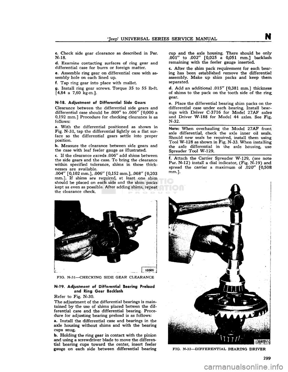
a.
With
the differential positioned as shown in
Fig.
N-31, tap the differential lightly on a flat
sur
face so the differential gears
settle
into
proper
position.
b. Measure the clearance
between
side gears and
the case with leaf feeler
gauge
as illustrated. c. If the clearance
exceds
.006" add shims
between
the side gears and the case. To bring the clearance
within specified tolerance, shims in
these
thick
nesses
are available.
.004"
[0,102
mm.], .006"
[0,152
mm.], .008"
[0,203
mm.].
If shims are required, at least one shim
should be placed on each side and the shim packs kept as even as possible. After adding shims, repeat
the clearance check.
10009
FIG.
N-31—CHECKING SIDE GEAR CLEARANCE N-l9.
Adjustment of
Differential
Bearing Preload
and
Ring
Gear
Backlash
Refer
to Fig. N-30.
The
adjustment of the differential bearings is main
tained by the use of shims placed
betwen
the dif
ferential case and the differential bearing. Proce
dure for adjusting bearing preload is as follows:
a.
Install
the differential case and bearings in the
axle housing without shims and with the bearing
cups snug.
b. Holding the ring gear in contact with the pinipn
and
using a screwdriver blade to
move
the differen
tial
bearing cups toward the center, insert feeler
gauge
on each side
between
differential bearing cup and the axle housing.
There
should be only
.001" to .002"
[0,025
a 0,051 mm.] backlash
remaining with the feeler
gauge
inserted.
c.
After the shim pack requirement for each bear
ing has
been
established remove the differential
assembly. Make up shim packs and
keep
them separated.
d.
Add an additional .015"
[0,381
mm.] thickness:
of shims to the pack on the
tooth
side of the ring gear.
e.
Place the differential bearing shim packs on the
differential case under each bearing.
Install
bear
ings
with
Driver
C-3716 for Model
27AF
axles
and
Driver
W-188 for Model 44 axles. See Fig. N-32.
Note:
When overhauling the Model
27AF
front
axle differential, check the axle inner oil seals. Should new seals be required, install them using
Tool
W-128 as shown in Fig. N-33. When installing
the axle differential in the axle housing, use
Spreader
Tool W-129.
f. Attach the
Carrier
Spreader W-129, (see
note
Par.
N-12) install a
dial
indicator, (Fig. N-19) and spread the
carrier
a maximum of .020"
[0,508
mm.].
FIG.
N-32—DIFFERENTIAL BEARING DRIVER
299
Page 300 of 376
N
REAR AXLE
11874
FIG.
N-33—INSTALLING INNER OIL SEALS — MODEL 27 FRONT
AXLE
DIFFERENTIAL g. Remove the indicator.
h.
Lubricate bearings and place the differential in
the
carrier.
i.
Tap the unit carefully
into
place with
soft
mallet, making sure the ring gear
teeth
mesh with the
pinion
teeth.
j.
Install bearing caps, matching their markings
with
those
on the
carrier.
k. Apply sealing compound to the screw threads.
Torque
the screws 70 to 90 lb-ft. [9,68 a 12,44
kg-m.].
I.
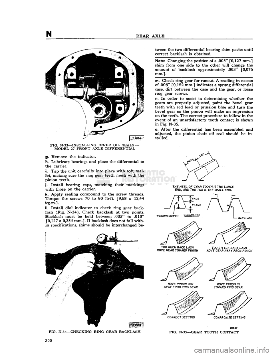
Install dial indicator to check ring gear back
lash
(Fig. N-34). Check backlash at two points.
Backlash
must be held
between
.005" to .010"
[0,127
a
0,254
mm.]. If backlash
does
not fall with
in
specifications, shims should be interchanged be
tween
the two differential bearing shim packs until
correct backlash is obtained.
Note:
Changing the position of a .005"
[0,127
mm.]
shim from one side to the other
will
change the
amount of backlash approximately .003"
[0,076
mm.].
m. Check ring gear for runout. A reading in
excess
of .006"
[0,152
mm.] indicates a sprung differential
case, dirt
between
the case and the gear, or
loose
ring
gear screws.
n.
In order to assist in determining whether the
gears are properly adjusted, paint the bevel gear
teeth
with red lead or prussion blue and turn the
bevel gear so the pinion
will
make an impression on the
teeth.
The correct procedure to
follow
in the
event
of an unsatisfactory
tooth
contact is shown
in Fig.
N-35.
o. After the differential has
been
assembled and
adjusted, the pinion shaft oil seal should be in
stalled.
THE
HEEL
OF
GEAR TOOTH
IS THE
LARGE
END,
AND THE TOE IS THE
SHALL
END.
WORKING DEPTH
TOO
MUCH BACK LASH
MOVE GEAR TOWARD PINION
TOO
LITTLE BACK LASH
MOVE GEAR AWAY FROM PINION
\:
US33
FIG.
N-34—CHECKING RING GEAR BACKLASH
MOVE
PINION
OUT
AWAY FROM RING GEAR MOVE PINION
IN
TOWARD RING GEAR
CORRECT SETTING COMPROMISE SETTING
10547
FIG.
N-35—GEAR
TOOTH CONTACT 300
Page 302 of 376
N
REAR
AXLE a.
Place the transmission in neutral.
b.
Raise one wheel off the floor and place a block
in
front and at the
rear
of the
opposite
wheel.
c.
Apply a torque wrench to the axle shaft nut of
the elevated wheel.
d.
Turn
wheel with torque wrench. Disregard
breakaway
torque and observe torque required to
continuously
turn
wheel smoothly. Torque should
read
40 lb-ft [5,53 kg-m.] or more.
N-23. Powr-Lok
Differential Disassembly
/
and Reassembly
Refer
to
Figs.
N-38 and N-39.
The
procedure for overhauling disc type
Powr-Lok
differentials is as follows:
a.
Remove axle shafts following procedure de
scribed
in Par. N-2.
b.
Remove housing cover and gasket.
c.
Remove the
Powr-Lok
differential from the axle.
Do not remove the ring gear or bearing
cone
and
rollers
unless replacement is to be made.
Mark
the hearing cups so they may later be reassembled
with
the same bearing cones.
Mark
the differential
case halves for correct alignment at reassembly.
Each
pinion mate cross shaft should also be marked
so that each pin cam surface
will
match with the
same
V-ramp
in the case when reassembled.
d.
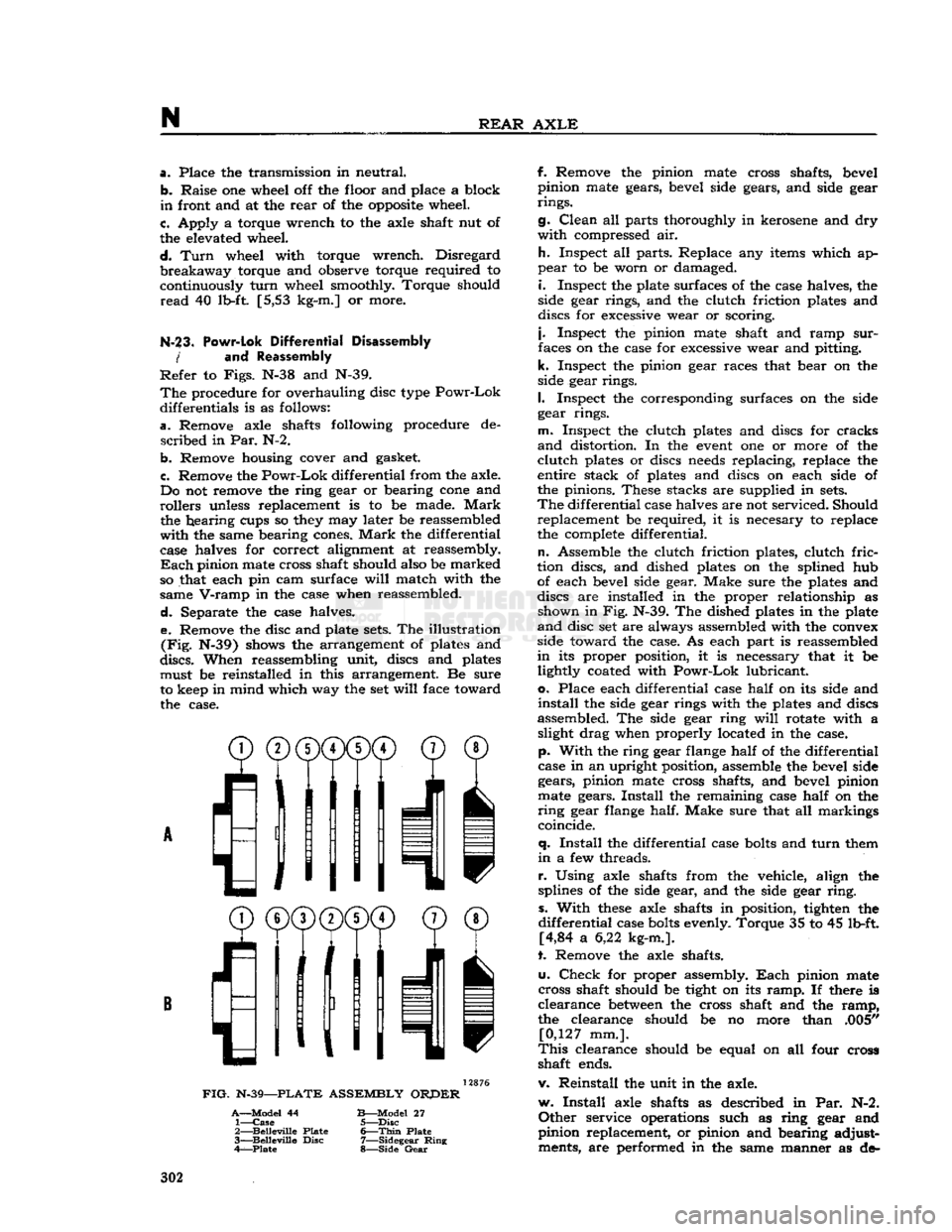
Separate the case halves. e. Remove the disc and plate
sets.
The illustration
(Fig.
N-39) shows the arrangement of plates and
discs.
When reassembling unit, discs and plates must be reinstalled in this arrangement. Be sure
to keep in mind which way the set
will
face toward the case.
^®(j)(j)CD©
® /'Ml
I
11
11 v
FIG.
N-39—PLATE
ASSEMBLY
ORPER
A—Model
44
B—Model
27 1—
Case
5—Disc
2—
Belleville
Plate
6—Thin
Plate
3—
Belleville
Disc
7—Sidegear
Ring
4—Plate
8—Side
Gear
f. Remove the pinion mate cross shafts, bevel
pinion mate gears, bevel side gears, and side gear
rings.
g.
Clean
all parts thoroughly in kerosene and dry
with
compressed air.
h.
Inspect all parts. Replace any items which ap
pear
to be worn or damaged.
i.
Inspect the plate surfaces of the case halves, the
side gear rings, and the clutch friction plates and
discs for excessive wear or scoring.
j.
Inspect the pinion mate shaft and ramp
sur
faces on the case for excessive wear and pitting,
k.
Inspect the pinion gear races that bear on the
side gear rings.
I.
Inspect the corresponding surfaces on the side
gear rings.
m.
Inspect the clutch plates and discs for cracks
and
distortion. In the
event
one or more of the
clutch
plates or discs
needs
replacing, replace the
entire stack of plates and discs on each side of
the pinions. These stacks are supplied in
sets.
The
differential case halves are not serviced. Should replacement be required, it is necesary to replace
the complete differential.
n.
Assemble the clutch friction plates, clutch
fric
tion discs, and dished plates on the splined hub of each bevel side gear. Make sure the plates and
discs are installed in the proper relationship as shown in Fig. N-39. The dished plates in the plate
and
disc set are always assembled with the convex
side toward the case. As each part is reassembled
in
its proper position, it is necessary that it be lightly coated with
Powr-Lok
lubricant,
o.
Place each differential case
half
on its side and
install
the side gear rings with the plates and discs
assembled. The side gear ring
will
rotate with a slight drag when properly located in the case,
p.
With
the ring gear flange
half
of the differential
case in an upright position, assemble the bevel side gears, pinion mate cross shafts, and bevel pinion
mate gears.
Install
the remaining case
half
on the
ring
gear flange half. Make sure that all markings
coincide.
q.
Install
the differential case
bolts
and
turn
them
in
a few threads.
r.
Using axle shafts from the vehicle, align the
splines of the side gear, and the side gear
ring,
s.
With
these
axle shafts in position, tighten the
differential
case
bolts
evenly. Torque 35 to 45 lb-ft. [4,84 a 6,22 kg-m.].
t. Remove the axle shafts.
u.
Check
for proper assembly.
Each
pinion mate
cross shaft should be tight on its
ramp.
If there is
clearance
between
the cross shaft and the
ramp,
the clearance should be no more than .005" [0,127 mm.].
This
clearance should be equal on all four cross
shaft ends.
v. Reinstall the unit in the axle.
w.
Install
axle shafts as described in Par. N-2.
Other
service operations such as ring gear and
pinion replacement, or pinion and bearing adjust ments, are performed in the same manner as de- 302
Page 304 of 376
N
REAR
AXLE
With
the
Trac-Lok
unit removed from the axle
housing, proceed as follows:
N-29.
Disassembly
a.
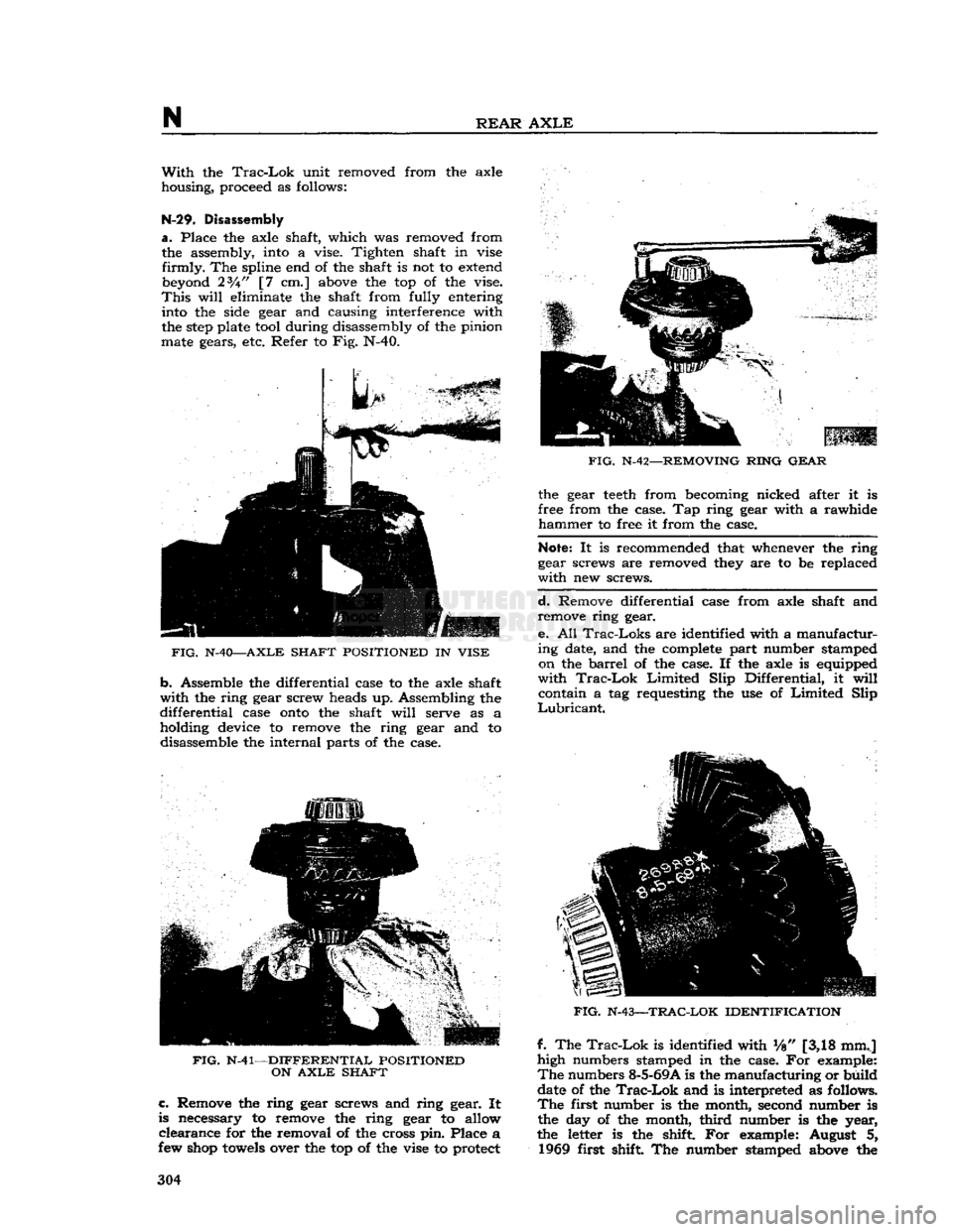
Place the axle shaft, which was removed from the assembly, into a vise. Tighten shaft in vise
firmly.
The spline end of the shaft is not to extend beyond 23A" [7 cm.] above the top of the vise.
This
will
eliminate the shaft from fully entering into the side gear and causing interference with
the
step
plate tool during disassembly of the pinion
mate gears, etc. Refer to Fig. N-40.
FIG.
N-40—AXLE SHAFT POSITIONED
IN
VISE
b.
Assemble the differential case to the axle shaft
with
the ring gear screw heads up. Assembling the
differential
case
onto
the shaft
will
serve as a holding device to remove the ring gear and to disassemble the internal parts of the case.
FIG.
N-41—DIFFERENTIAL POSITIONED
ON
AXLE
SHAFT c.
Remove the ring gear screws and ring gear. It
is necessary to remove the ring gear to allow
clearance
for the removal of the cross pin. Place a
few shop
towels
over the top of the vise to protect
FIG.
N-42—REMOVING RING
GEAR
the gear
teeth
from becoming nicked after it is
free from the case. Tap ring gear with a rawhide
hammer
to free it from the case.
Note:
It is recommended that whenever the ring
gear screws are removed they are to be replaced
with
new screws.
d.
Remove differential case from axle shaft and remove ring gear.
e. All
Trac-Loks
are identified with a manufactur
ing date, and the complete part number stamped on the
barrel
of the case. If the axle is equipped
with
Trac-Lok
Limited
Slip Differential, it
will
contain a tag requesting the use of
Limited
Slip
Lubricant.
FIG.
N-43—TRAC-LOK IDENTIFICATION
f. The
Trac-Lok
is identified with Vs" [3,18 mmj
high numbers stamped in the case. For example:
The
numbers 8-5-69A is the manufacturing or build
date of the
Trac-Lok
and is interpreted as follows.
The
first number is the month, second number is
the day of the month,
third
number is the year,
the letter is the shift. For example: August 5, 1969 first shift The number stamped above the 304
Page 305 of 376
'Jeep'
UNIVERSAL
SERIES
SERVICE
MANUAL
N
FIG.
N-44—REMOVING
SNAP
RINGS
FROM
CROSS
PIN
manufacturing
date is the complete
Trac-Lok
as
sembly part number.
g. It is recommended that when referring to the
Trac-Lok,
obtain the complete part number and
build
date. To do this it
will
be necessary to wipe
off the lubricant from the case. See Fig. N-43.
h.
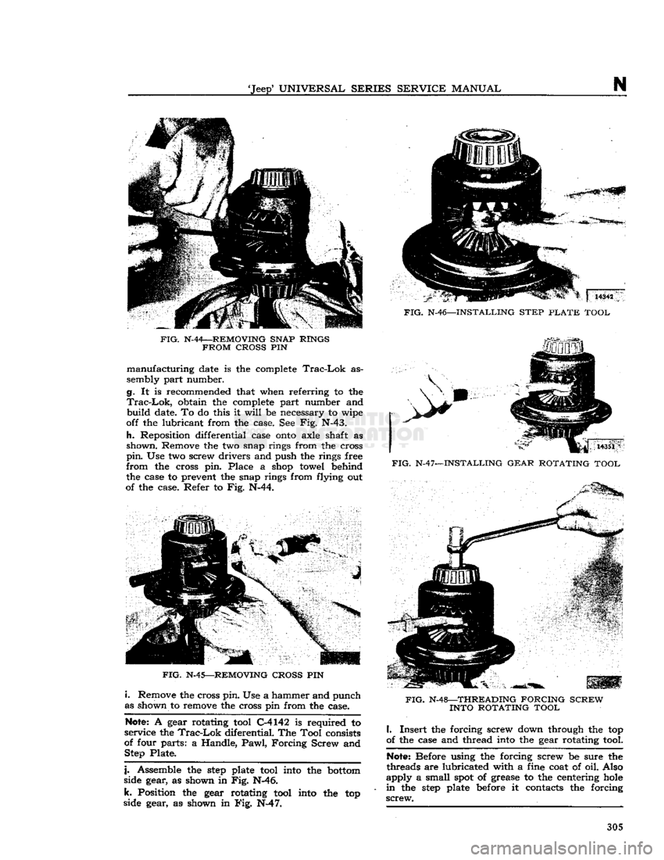
Reposition differential case
onto
axle shaft as
shown. Remove the two snap rings from the cross
pin.
Use two screw drivers and push the rings free
from
the cross pin. Place a shop towel behind
the case to prevent the snap rings from flying out
of the case. Refer to Fig. N-44.
FIG.
N-45—REMOVING CROSS
PIN
i.
Remove the cross pin. Use a hammer and punch
as shown to remove the cross pin from the case.
Note: A gear rotating tool C-4142 is required to
service the
Trac-Lok
diferential. The Tool consists
of four parts: a Handle,
Pawl,
Forcing
Screw and Step Plate.
j.
Assemble the
step
plate tool into the bottom
side gear, as shown in Fig. N-4 6.
k.
Position the gear rotating tool into the top
side gear, as shown in Big. N-4 7. "S | 14342
FIG.
N-46—INSTALLING STEP
PLATE
TOOL
V
14351
FIG.
N-47—INSTALLING GEAR ROTATING TOOL
FIG.
N-48—THREADING FORCING SCREW INTO ROTATING TOOL
I.
Insert the forcing screw down through the top
of the case and thread into the gear rotating tool.
Note: Before using the forcing screw be sure the
threads are lubricated with a fine coat of oil. Also
apply
a small spot of grease to the centering hole
in
the
step
plate before it contacts the forcing
screw.
305
Page 315 of 376
'Jeep'
UNIVERSAL
SERIES SERVICE
MANUAL
O Note:
If the steering-gear-to-frame
bolts
are not
properly
torqued, they
will
eventually
loosen
dur
ing operation of the vehicle. Loose
bolts
will
result
in
elongated
bolt
holes
making maintenance of bolt torque difficult, and may allow position of the
steering columns to be misaligned. Therefore,
proper
torquing is extremely important.
Do not tighten the steering gear to dampen out
steering trouble. Adjust the steering gear only to
remove lost motion or play within the unit.
0-5. Steering
Gear
Adjustment
The
cam and lever steering gear is illustrated in
Fig.
0-2. It consists of a
spiral
cam, and a cross shaft and lever assembly with two lever studs.
When
the steering wheel is turned, the cam
moves
the studs, causing rotary movement of the cross
shaft, which in
turn
causes angular movement of
the*steering arm.
Two
adjustments of the steering gear are necessary:
up and down play of the steering shaft, and adjustment of the lever studs (tapered pins) in the
cam
groove.
Adjustment
of the
ball
thrust bearings to eliminate up and down play of the steering shaft is ac
complished by removing shims which are installed
between
the steering gear housing and the upper
cover. Before making this adjustment
loosen
the
housing side cover adjusting screw to free the pins
in
the cam groove. Loosen the housing cover to
cut and remove a shim or more as required.
Install
the screws and tighten. Adjustment should be
made to have a slight drag but allow the steering
wheel to
turn
freely with thumb and forefinger
lightly gripping the rim.
Shims
installed for adjustment are .002*, .003", and .010"
[.0508,
.0762
and .254 mm.] in thickness.
Adjustment
of the tapered pins in the cam
groove
is accomplished by adjusting screw. Unlock the
adjusting
screw and
turn
it in until a very slight
drag
is felt through the mid-position when turning
the steering wheel slowly from one extreme position
to the other.
Backlash
of the pins in the
groove
shows up as
end play of lever shaft, also as backlash of steer ing arm.
The
cam
groove
is purposely cut shallow in the
straight
ahead driving position for each pin.
This
feature permits a
close
adjustment for normal
straight
ahead driving and provides precision steer ing and permits take up of backlash at this point
after the wear occurs without causing a bind else
where.
Always
adjust within the high range through
the mid-position of pin travel. Do not adjust off
"straight
ahead" position.
Backlash
in turned posi
tions is not objectionable.
0-6.
Front
Wheel Alignment Adjustments
To
ensure correct alignment, a definite procedure
for inspection of the steering system is recom mended. It is
suggested
that the following sequence
be used:
a.
Equalize
tire pressures and level vehicle.
b.
Check
steering gear to steering column align
ment.
c.
Inspect steering knuckle pivots, spindle, and
wheel bearing
looseness.
d.
Check
wheel runout.
e.
Test wheel balance and bearing adjustment.
f.
Check
for spring sag.
g.
Inspect brakes and shock absorbers.
h.
Check
steering gear assembly adjustment and
steering connecting rod.
i.
Check
caster,
j.
Check
toe-in.
k.
Check
toe-out
on turns.
I.
Check
camber.
m.
Check
tracking of front and
rear
wheels,
n.
Check
frame alignment.
The
factors of alignment, caster, camber, and toe-
in,
are all interrelated and if one adjustment is
made, another adjustment may be affected.
There
fore, after an alignment job is completed, make a
complete recheck of all the adjustments to be sure
the
settings
are within the limit. Be sure all front
suspension and steering system nuts and
bolts
are
all
properly torqued before taking wheel alignment readings.
Proper
alignment of front wheels must be main
tained in order to ensure
ease
of steering and satisfactory tire life.
The
most important factors of front wheel alignment are wheel camber, axle caster and wheel
toe-in.
Wheel
toe-in is the distance the wheels are closer
together
at the front than at the
rear.
Wheel
camber is the amount the wheels incline out
ward
at the top from a vertical position.
Front
axle caster is the amount in
degrees
that the
steering pivot pins are tilted towards the front or
rear
of the vehicle. Positive caster is inclination of
the top of the pivot pin towards the
rear
of the ve
hicle.
Zero caster is the vertical position of the
pivot pin. Negative or reverse caster is the in
clination
of the top of the pin towards the front
of the vehicle.
These
points should be checked at regular inter
vals,
particularly when the front axle has been
subjected to a heavy impact. When checking wheel alignment, it is important that wheel bearings and
knuckle
bearings be in proper adjustment. Loose bearings
will
affect instrument readings when
checking
the camber, pivot pin inclination and
toe-in.
To
accurately check camber and caster, use a wheel
aligning fixture.
Camber
and caster of the front
wheels are both preset.
Camber
cannot be altered
but caster can be adjusted by installing caster shims
between
the axle pad and the springs. Wheel toe-in
may
be adjusted. To measure wheel toe-in, use a
wheel aligning fixture or follow the procedure given
in Par.
0-8.
0-7.
Front Wheel Toe-in
Toe-in
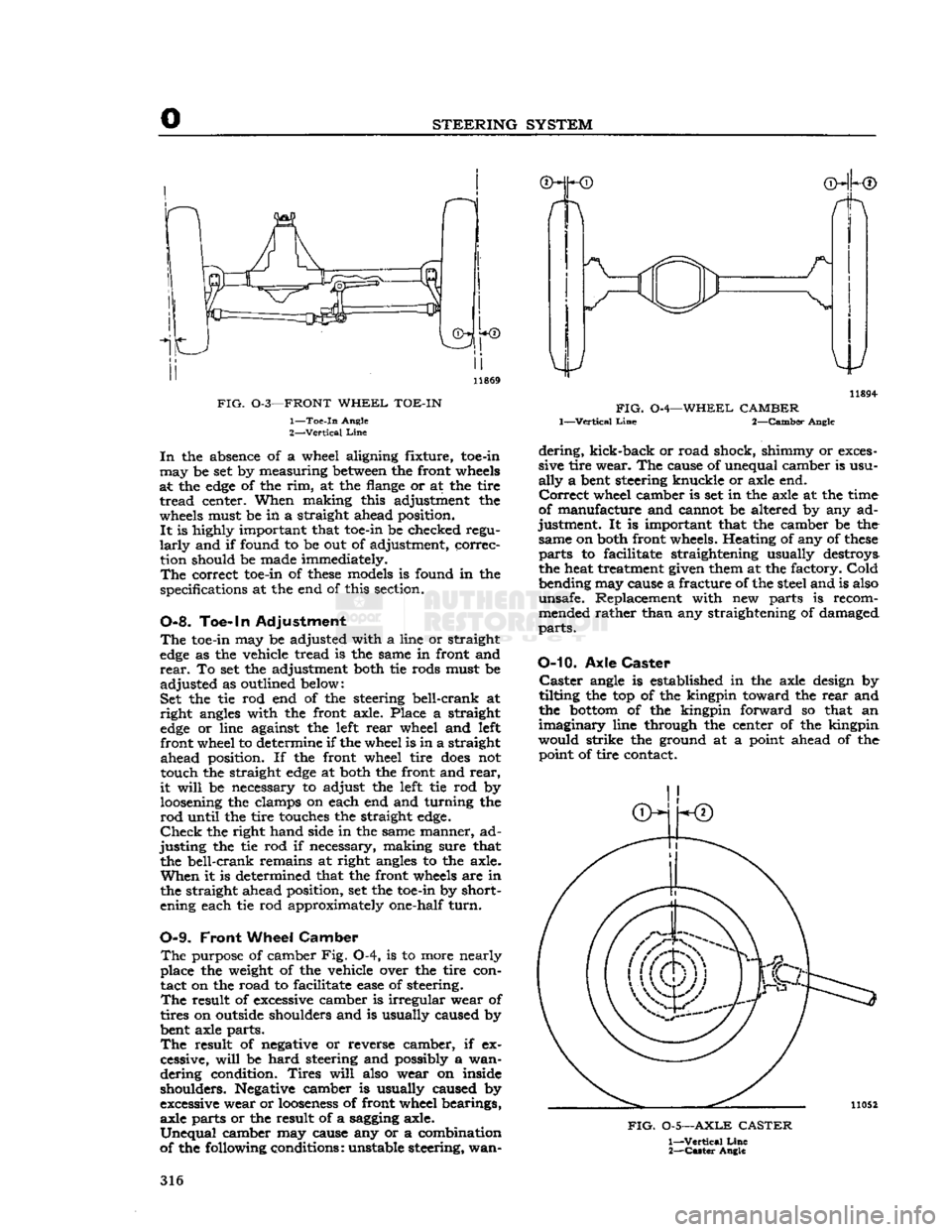
as illustrated in
Fig.
0-3, is necessary to
off
set the
effect
of camber as shown in Fig. Q-4. 315
Page 316 of 376
o
STEERING SYSTEM
FIG.
0-3—FRONT
WHEEL
TOE-IN
1—
Toe-in
Angle
2—
Vertical
Line
In
the absence of a wheel aligning fixture, toe-in
may
be set by measuring
between
the front wheels
at the
edge
of the rim, at the flange or at the tire
tread
center. When making this adjustment the
wheels must be in a straight ahead position.
It
is highly important that toe-in be checked regu
larly
and if found to be out of adjustment, correc tion should be made immediately.
The
correct toe-in of
these
models is found in the
specifications at the end of this section.
0-8. Toe-in Adjustment
The
toe-in may be adjusted with a line or straight
edge
as the vehicle tread is the same in front and
rear.
To set the adjustment both tie rods must be
adjusted
as outlined below:
Set the tie rod end of the steering bell-crank at
right
angles with the front axle. Place a straight
edge
or line against the left
rear
wheel and left front wheel to determine if the wheel is in a straight
ahead
position. If the front wheel tire
does
not touch the straight
edge
at both the front and
rear,
it
will
be necessary to adjust the left tie rod by loosening the clamps on each end and turning the
rod
until the tire touches the straight
edge.
Check
the right hand side in the same manner, ad
justing
the tie rod if necessary, making sure that the bell-crank remains at right angles to the axle.
When
it is determined that the front wheels are in the straight ahead position, set the toe-in by short
ening each tie rod approximately one-half
turn.
0-9.
Front
Wheel
Camber
The
purpose of camber Fig. 0-4, is to more nearly
place the weight of the vehicle over the tire con tact on the road to facilitate
ease
of steering.
The
result of excessive camber is irregular wear of
tires on outside shoulders and is usually caused by
bent axle parts.
The
result of negative or reverse camber, if ex
cessive,
will
be
hard
steering and possibly a wan
dering
condition.
Tires
will
also wear on inside shoulders. Negative camber is usually caused by
excessive wear or
looseness
of front wheel bearings, axle parts or the result of a sagging axle.
Unequal
camber may cause any or a combination
of the following conditions: unstable steering, wan- 11894-
FIG.
0-4—WHEEL CAMBER
1—Vertical
Line
2—Camber Angle
dering,
kick-back or road shock, shimmy or exces
sive tire wear. The cause of unequal camber is usu
ally
a bent steering knuckle or axle end.
Correct
wheel camber is set in the axle at the time
of manufacture and cannot be altered by any ad
justment. It is important that the camber be the same on both front wheels. Heating of any of
these
parts
to facilitate straightening usually destroys
the heat treatment given them at the factory.
Cold
bending may cause a fracture of the steel and is also
unsafe. Replacement with new parts is recom mended rather than any straightening of damaged
parts.
O-10.
Axle
Caster Caster
angle is established in the axle design by
tilting the top of the kingpin toward the
rear
and
the
bottom
of the kingpin forward so that an
imaginary
line through the center of the kingpin
would strike the ground at a point ahead of the point of tire contact.
FIG.
0-5—AXLE
CASTER
1—
Vertical
Line
2—
Caster
Angle
316
Page 319 of 376
'Jeep*
UNIVERSAL
SERIES SERVICE
MANUAL
D
©—P3
10789
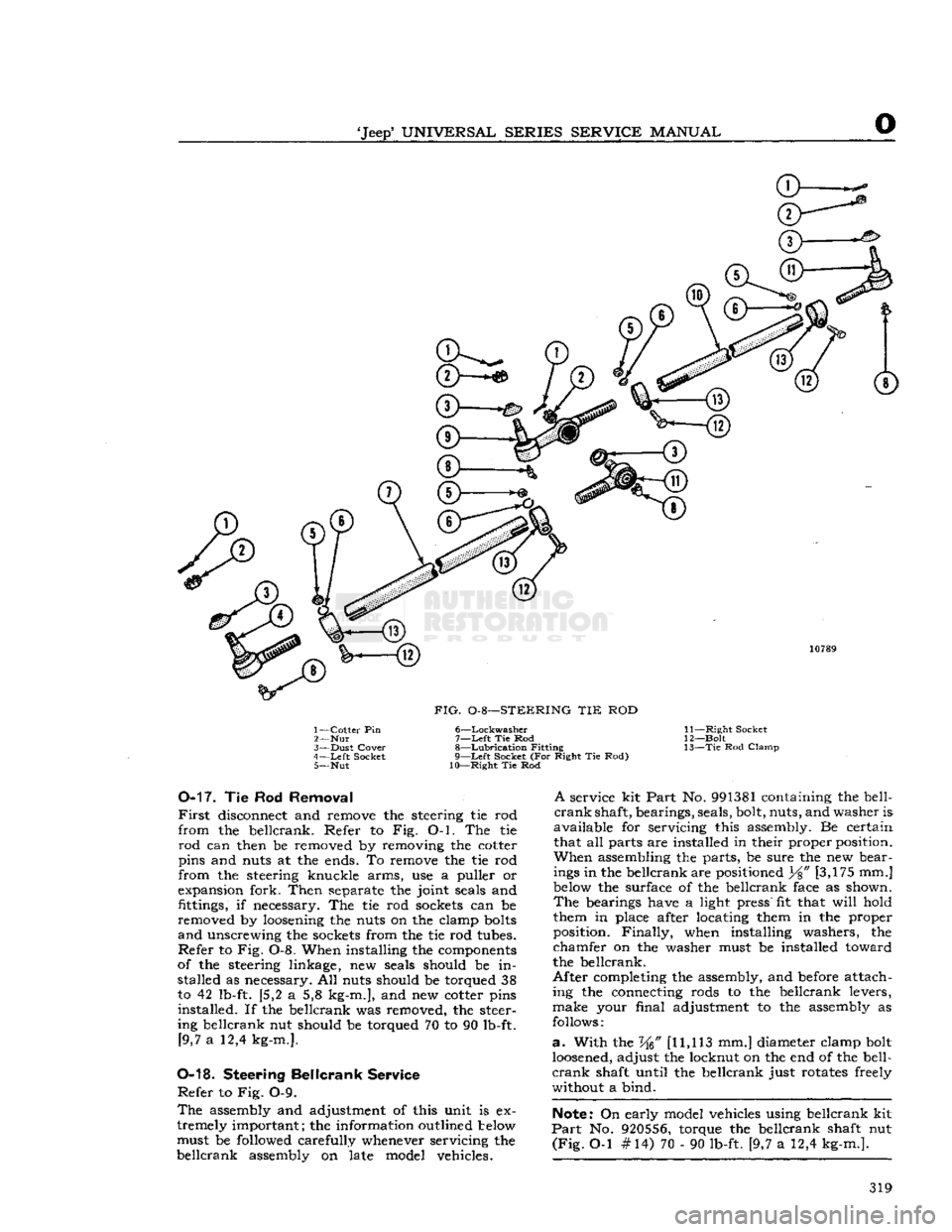
FIG.
0-8—STEERING TIE ROD
1—
Cotter
Pin 6—Lockwasher
2—
Nut 7—Left Tie Rod
3—
Dust
Cover
8—Lubrication
Fitting
4—
Left
Socket 9—Left Socket (For Right Tie Rod) 5— Nut 10—Right Tie Rod 11—
Right
Socket
12—
Bolt
13— Tie
Rod
Clamp
0-17.
Tie Rod
Removal
First
disconnect and remove the steering tie rod
from
the bellcrank. Refer to Fig. O-l. The tie
rod
can then be removed by removing the cotter
pins and
nuts
at the
ends.
To remove the tie rod
from
the steering knuckle arms, use a puller or
expansion
fork.
Then
separate
the
joint
seals
and
fittings,
if
necessary.
The tie rod
sockets
can be
removed by loosening the
nuts
on the clamp bolts
and unscrewing the
sockets
from
the tie rod
tubes.
Refer to Fig. 0-8. When installing the
components
of
the steering linkage, new
seals
should be in stalled as
necessary.
All
nuts
should be torqued 38
to 42
lb-ft.
{5,2 a 5,8
kg-m.],
and new cotter pins
installed.
If the bellcrank was removed, the
steer
ing
bellcrank nut should be torqued 70 to 90
lb-ft.
[9,7
a 12,4
kg-m.].
0-18.
Steering
Bellcrank
Service
Refer to Fig. 0-9.
The
assembly
and adjustment of this unit is ex
tremely important; the information outlined below must be
followed
carefully whenever servicing the
bellcrank
assembly
on late model vehicles.
A
service kit
Part
No. 991381 containing the
bell
crank shaft, bearings,
seals,
bolt, nuts, and
washer
is
available for servicing this
assembly.
Be certain that all
parts
are installed in their proper position.
When assembling the parts, be
sure
the new
bear
ings in the bellcrank are positioned
Y%"
[3,175 mm.]
below the
surface
of the bellcrank
face
as shown. The
bearings
have
a
light
press"
fit that
will
hold
them in
place
after locating them in the proper
position.
Finally, when installing
washers,
the
chamfer on the
washer
must be installed toward
the bellcrank.
After
completing the
assembly,
and before attach
ing
the connecting
rods
to the bellcrank levers,
make
your
final
adjustment to the
assembly
as
follows:
a.
With
the W [11,113 mm.] diameter clamp bolt
loosened, adjust the locknut on the end of the
bell
crank shaft
until
the bellcrank just
rotates
freely
without
a bind.
Note:
On early model vehicles using bellcrank kit
Part
No. 920556, torque the bellcrank shaft nut
(Fig.
O-l #14) 70 - 90
lb-ft.
[9,7 a 12,4
kg-m.].
319