tow JEEP CJ 1953 User Guide
[x] Cancel search | Manufacturer: JEEP, Model Year: 1953, Model line: CJ, Model: JEEP CJ 1953Pages: 376, PDF Size: 19.96 MB
Page 94 of 376
Dl
DAUNTLESS
V-6
ENGINE
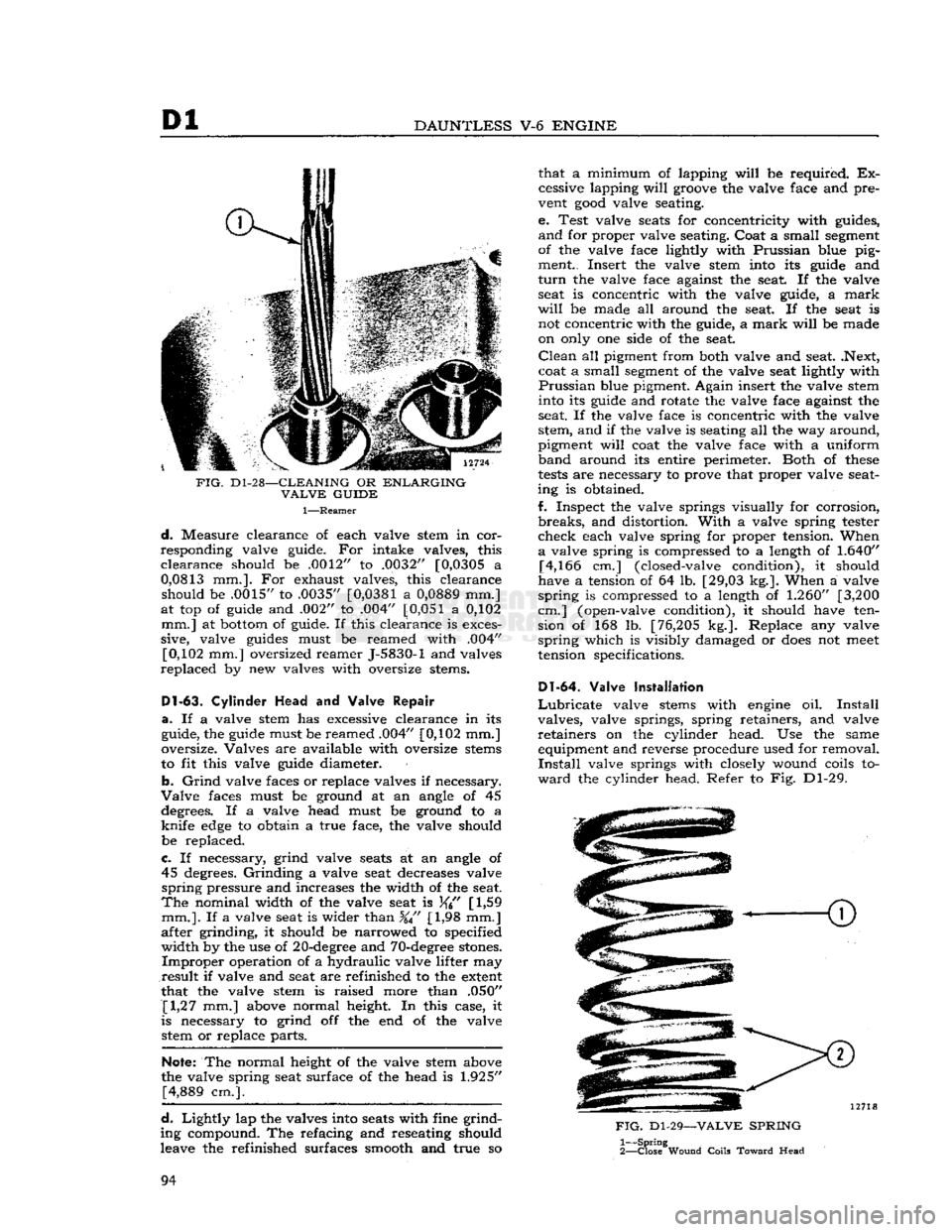
FIG.
D1-28—CLEANING
OR
ENLARGING
VALVE
GUIDE
1—Reamer
d.
Measure clearance of each valve stem in cor
responding valve guide. For intake valves, this
clearance
should be .0012" to .0032" [0,0305 a
0,0813
mm.]. For exhaust valves, this clearance should be .0015" to .0035"
[0,0381
a
0,0889
mm.]
at top of guide and .002" to .004"
[0,051
a 0,102 mm.] at bottom of guide. If this clearance is exces
sive, valve guides must be reamed with .004" [0,102 mm.] oversized reamer J-5830-1 and valves
replaced
by new valves with oversize stems.
Dl-63.
Cylinder
Head
and Valve
Repair
a.
If a valve stem has excessive clearance in its
guide, the guide must be reamed .004" [0,102 mm.]
oversize. Valves are available with oversize stems
to fit this valve guide diameter.
b.
Grind
valve faces or replace valves if necessary.
Valve
faces must be ground at an angle of 45 degrees. If a valve head must be ground to a
knife
edge
to obtain a true face, the valve should
be replaced.
c.
If necessary, grind valve seats at an angle of 45 degrees.
Grinding
a valve seat decreases valve
spring
pressure and increases the width of the seat.
The
nominal width of the valve seat is
[
1,59
mm.].
If a valve seat is wider than %" [1,98 mm.]
after grinding, it should be narrowed to specified
width
by the use of 20-degree and 70-degree stones.
Improper
operation of a hydraulic valve lifter may
result
if valve and seat are refinished to the extent
that the valve stem is raised more than .050" [1,27 mm.] above normal height. In this case, it
is necessary to grind off the end of the valve stetti or replace parts.
Note:
The normal height of the valve stem above
the valve spring seat surface of the head is
1.925"
[4,889 cm.].
d.
Lightly
lap the valves into seats with fine grind
ing compound. The refacing and reseating should
leave the refinished surfaces smooth and true so that a minimum of lapping
will
be required. Ex
cessive lapping
will
groove the valve face and pre
vent
good
valve seating.
e. Test valve seats for concentricity with guides,
and
for proper valve seating. Coat a small segment
of the valve face lightly with Prussian blue pig ment.. Insert the valve stem into its guide and
turn
the valve face against the seat. If the valve seat is concentric with the valve guide, a
mark
will
be made all around the seat. If the seat is not concentric with the guide, a
mark
will
be made
on only one side of the seat.
Clean
all pigment from both valve and seat. .Next,
coat a small segment of the valve seat lightly with
Prussian
blue pigment. Again insert the valve stem into its guide and rotate the valve face against the
seat. If the valve face is concentric with the valve
stem, and if the valve is seating all the way around,
pigment
will
coat the valve face with a uniform
band
around its entire perimeter. Both of
these
tests
are necessary to prove that proper valve seat
ing is obtained.
f. Inspect the valve springs visually for corrosion,
breaks,
and distortion.
With
a valve spring tester
check
each valve spring for proper tension. When
a
valve spring is compressed to a length of
1.640"
[4,166 cm.] (closed-valve condition), it should
have a tension of 64 lb. [29,03 kg.]. When a valve
spring
is compressed to a length of
1.260"
[3,200
cm.] (open-valve condition), it should have ten sion of 168 lb. [76,205 kg.]. Replace any valve
spring
which is visibly damaged or
does
not
meet
tension specifications.
Dl-64.
Valve Installation
Lubricate
valve stems with engine oil.
Install
valves, valve springs, spring retainers, and valve
retainers
on the cylinder head. Use the same equipment and reverse procedure used for removal.
Install
valve springs with closely wound coils to
ward
the cylinder head. Refer to Fig. Dl-29.
FIG.
Dl-29—VALVE
SPRING
1—
Spring
2—
Close
Wound
Coils
Toward
Head
94
Page 97 of 376
'Jeep'
UNIVERSAL
SERIES SERVICE
MANUAL
Dl
size have
been
selected. If necessary, check or
select
connecting rod bearings as described in Par. Dl-49.
Note:
When a piston and connecting rod assembly
is properly installed, the oil spurt
hole
in the con necting rod
will
face the camshaft. The rib on the
edge
of the bearing cap
will
be on the same side
as the conical
boss
on the connecting rod web;
these
marks (rib and boss)
will
be toward the other
connecting rod on the same crankpin. The notch
on the piston
will
face the front of the
engine.
a.
Be certain that cylinder bores, pistons, connect
ing rod bearings and crankshaft journals are absolutely clean. Coat all bearing surfaces with
engine
oil.
b. Before installing a piston and connecting rod as
sembly into its bore, rotate the crankshaft so that
the corresponding crankpin is moved downward, away from the cylinder bore.
c. Remove bearing cap from connecting rod. With
upper bearing half seated in connecting rod, install connecting rod guides. These
guides
hold the upper
bearing half in place and prevent damage to the
crankshaft
crankpin during installation of the con
necting rod and piston assembly.
d.
Be certain that the gap in the oil ring rails faces
upward,
toward center of
engine.
Gaps of the com
pression rings shall not be aligned with each other
or
with the oil ring
rails.
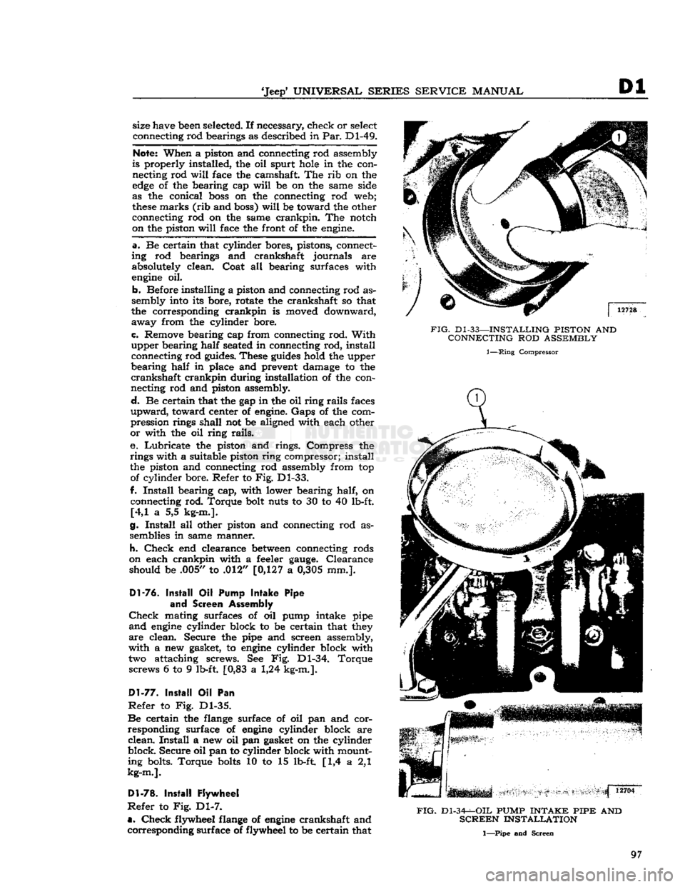
e. Lubricate the piston and rings. Compress the
rings with a suitable piston ring compressor; install
the piston and connecting rod assembly from top of cylinder bore. Refer to Fig. Dl-33.
f.
Install
bearing cap, with lower bearing half, on connecting rod. Torque bolt nuts to 30 to 40 lb-ft. [4,1 a 5,5 kg-m.].
g.
Install
all other piston and connecting rod as
semblies in same manner.
h.
Check
end clearance
between
connecting rods
on each crankpin with a feeler
gauge.
Clearance should be .005,/ to .012" [0,127 a
0,305
mm.].
Dl-76.
Install
Oil
Pump
Intake
Pipe
and
Screen Assembly
Check
mating surfaces of oil pump intake pipe
and
engine
cylinder block to be certain that they
are
clean. Secure the pipe and screen assembly,
with a new gasket, to
engine
cylinder block with two attaching screws. See Fig. Dl-34. Torque screws 6 to 9 lb-ft. [0,83 a 1,24 kg-m.].
Dl-77.
Install
Oil Pan
Refer
to Fig. Dl-35.
Be
certain the flange surface of oil pan and cor
responding surface of
engine
cylinder block are
clean.
Install
a new oil pan gasket on the cylinder
block.
Secure
oil pan to cylinder block with mount ing bolts. Torque
bolts
10 to 15 lb-ft [1,4 a 2,1
kg-m.].
Dl-78.
Install
Flywheel
Refer
to Fig. Dl-7.
a.
Check
flywheel flange of
engine
crankshaft and corresponding surface of flywheel to
be
certain that
FIG.
Dl-33—INSTALLING
PISTON
AND
CONNECTING
ROD
ASSEMBLY
1—Ring
Compressor
FIG.
Dl-34-^-OIL
PUMP
INTAKE PIPE
AND
SCREEN
INSTALLATION
1—Pipe and Screen
97
Page 99 of 376
'Jeep'
UNIVERSAL SERIES SERVICE
MANUAL
Dl
both are clean. Any foreign material on either of
these
surfaces
will
cause flywheel run out and en
gine
vibration. Position flywheel to crankshaft and
secure with six mounting bolts. Torque mounting
bolts
50 to 65 lb-ft. [6,91 a 8,98 kg-m.].
Note:
Flywheel mounting
bolts
are unevenly
spaced so that flywheel can be installed in only
one position.
This
assures correct balance of fly
wheel and crankshaft.
b.
Mount a
dial
indicator on flywheel housing
flange of cylinder block and index its plunger to
the flywheel surface. Measure flywheel run out.
Maximum
allowable run out is .015"
[0,381
mm.].
Dl-82.
Install
Cylinder
Head Assembly
Refer
to Fig. Dl-9.
a.
Wipe cylinder head face of
engine
cylinder
block, and be certain no foreign material has fallen
into the cylinder bores, bolt holes, or in the valve
lifter
area.
It is
good
practice to clean out bolt
holes
with compressed air.
b.
Install
a new cylinder head gasket on the
cylin
der
block. Dowels in the block
will
hold the gasket
in
position. Always handle gaskets carefully to
avoid
kinking or damage to the surface treatment
of the gasket. Apply Perfect Seal Aerosol
Spray
Sealer
Part
No.
994757
on cylinder head gaskets.
Dl-79.
Install
Clutch
and Flywheel Housing
a.
Note
marks made on clutch assembly and fly
wheel during
engine
disassembly. Position clutch
assembly to flywheel, according to
marks,
and
fasten
loosely
with six attaching bolts. Torque
bolts
in rotation, one
turn
at a time, to 30 to 40 lb-ft. [4,1 a 5,5 kg-m.].
b.
Engage fork of clutch linkage to clutch and
position flywheel housing to
engine
cylinder block.
Secure
housing to block with six mounting bolts.
Torque
bolts
30 to 40 lb-ft. [4,1 a 5,5 kg-m.].
D1-80.
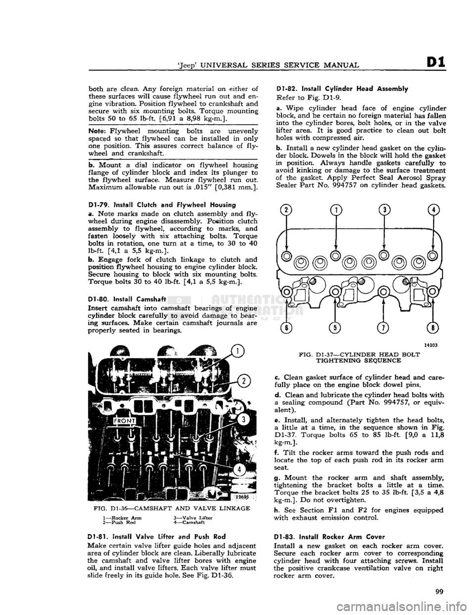
Install
Camshaft
Insert
camshaft into camshaft bearings of
engine
cylinder
block carefully to avoid damage to bear
ing surfaces. Make certain camshaft journals are
properly
seated in bearings.
12695
FIG.
D1-36—CAMSHAFT
AND
VALVE LINKAGE
1—
Rocker
Arm
2—
Push
Rod 3—
Valve
Lifter
4—
Camshaft
14203
FIG.
Dl-37—CYLINDER
HEAD
BOLT TIGHTENING SEQUENCE c.
Clean
gasket surface of cylinder head and care
fully
place on the
engine
block dowel pins.
d.
Clean
and lubricate the cylinder head
bolts
with
a
sealing compound
(Part
No. 994757, or equiv
alent).
e.
Install,
and alternately tighten the head bolts,
a
little at a time, in the sequence shown in Fig.
Dl-37.
Torque
bolts
65 to 85 lb-ft. [9,0 a 11,8
kg-m.].
f.
Tilt
the rocker arms toward the push rods and locate the top of each push rod in its rocker arm
seat.
g.
Mount the rocker arm and shaft assembly, tightening the bracket
bolts
a little at a time.
Torque
the bracket
bolts
25 to 35 lb-ft. [3,5 a 4,8
kg-m.].
Do not overtighten.
h.
See Section Fl and F2 for
engines
equipped
with
exhaust emission control.
D1-81.
Install
Valve Lifter
and Push Rod
Make
certain valve lifter guide
holes
and adjacent
area
of cylinder block are clean.
Liberally
lubricate
the camshaft and valve lifter bores with
engine
oil,
and install valve lifters.
Each
valve lifter must slide freely in its guide hole. See Fig. Dl-36.
Dl-83.
Install
Rocker Arm Cover
Install
a new gasket on each rocker arm cover.
Secure
each rocker arm cover to corresponding
cylinder
head with four attaching screws.
Install
the positive crankcase ventilation valve on right
rocker
arm cover. 99
Page 106 of 376
Dl
DAUNTLESS
V-6
ENGINE
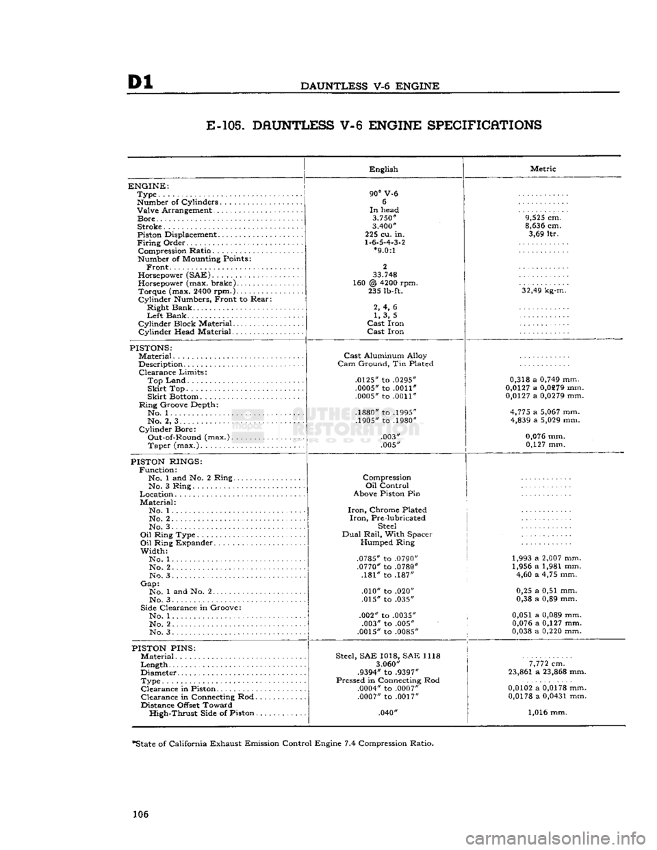
E-105.
DAUNTLESS V-6 ENGINE SPECIFICATIONS
ENGINE:
Type
Number
of Cylinders Valve Arrangement
Bore
Stroke
Piston
Displacement
Firing
Order Compression Ratio
Number
of
Mounting
Points:
Front.
Horsepower
(SAE)
Horsepower
(max. brake) Torque (max.
2400
rpm.)
Cylinder
Numbers,
Front to Rear:
Right Bank
Left
Bank
Cylinder Block Material
Cylinder Head Material English
90°
V-6 6
In
head
3.750"
3.400"
225 cu. in.
1.6.5.4.3.2
*9.0:1
2
33.748
160 @
4200
rpm. 235
lb-ft.
2, 4, 6 1, 3, 5
Cast
Iron
Cast
Iron Metric
9,525
cm.
8,636
cm. 3,69 ltr.
32,49
kg-m.
PISTONS:
Material
Description Clearance Limits:
Top
Land
Skirt
Top
Skirt
Bottom
Ring Groove Depth*. No. 1
No. 2, 3
Cylinder Bore: Out-of-Round (max.). Taper (max.)
Cast
Aluminum Alloy
Cam
Ground, Tin Plated
.0125"
to
.0295" .0005"
to
.0011"
.0005"
to
.0011"
.1880"
to
.1995"
.1905"
to
.1980"
.003"
.005" 0,318 a
0,749
mm.
0,0127
a
0,0279
mm.
0,0127
a
0,0279
mm.
4,775
a
5,067
mm.
4,839
a
5,029
mm.
0,076
mm. 0,127 mm.
PISTON
RINGS:
Function: No. 1 and No. 2 Ring.. No. 3 Ring
Location
Material: No. 1...
No. 2 No. 3.
Oil
Ring Type
Oil
Ring Expander
Width: No. 1
No. 2. .
No. 3
Gap:
No. 1 and No. 2
No. 3
Side
Clearance in Groove: No. 1
No. 2
No. 3 Compression
Oil
Control
Above
Piston
Pin
Iron,
Chrome Plated
Iron,
Pre lubricated
Steel
Dual
Rail,
With Spacer Humped Ring
.0785"
to
.0790" .0770"
to
.0780"
.181" to .187"
.010" to .020"
.015" to .035"
.002" to
.0035"
.003" to .005"
.0015"
to
.0085"
1,993 a
2,007
mm.
1,956 a 1,981 mm. 4,60 a 4,75 mm.
0,25 a 0,51 mm.
0,38 a 0,89 mm.
0,051 a
0,089
mm.
0,076
a 0,127 mm.
0,038
a
0,220
mm.
PISTON
PINS:
Material
Length
Diameter
Type Clearance in
Piston
Clearance in
Connecting
Rod.
Distance
Offset
Toward High-Thrust
Side
of Piston.
Steel,
SAE 1018, SAE 1118
3.060"
.9394"
to
.9397"
Pressed in
Connecting
Rod
.0004"
to
.0007" .0007"
to
.0017"
.040"
7,772
cm.
23,861
a
23,868
mm.
0,0102
a
0,0178
mm.
0,0178
a
0,0431
mm.
1,016 mm.
*State
of California Exhaust Emission Control Engine 7.4 Compression Ratio.
106
Page 115 of 376
'Jeep*
UNIVERSAL
SERIES
SERVICE
MANUAL
E
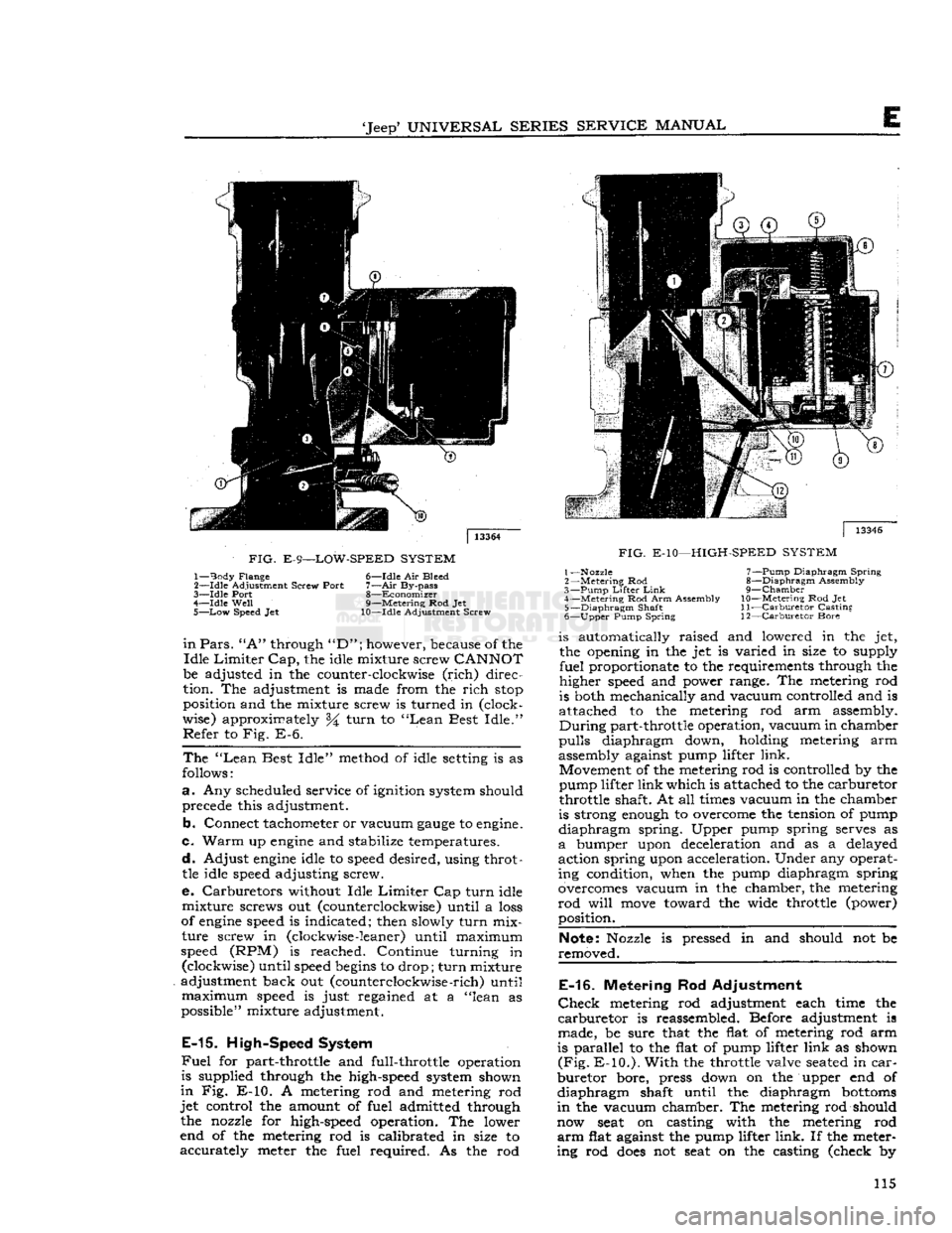
FIG.
E-9—LOW-SPEED
SYSTEM
1—
Body
Flange 6—Idle Air Bleed
2—
-Idle
Adjustment Screw Port
7—Air
By-pass
3—
Idle
Port 8—Economizer
4—
Idle
Well
9—Metering Rod Jet
5—
Low
Speed Jet 10—Idle Adjustment Screw
in
Pars.
"A"
through
"D";
however, because of the
Idle
Limiter
Cap,
the idle mixture screw
CANNOT
be adjusted in the counter-clockwise
(rich)
direc
tion. The adjustment is made from the
rich
stop
position and the mixture screw is turned in (clock
wise) approximately %
turn
to
"Lean
Best
Idle."
Refer
to Fig. E-6.
The
"Lean
Best
Idle"
method of idle
setting
is as
follows:
a.
Any scheduled service of ignition system should precede this adjustment.
b.
Connect tachometer or vacuum
gauge
to
engine.
c.
Warm
up
engine
and stabilize temperatures.
d.
Adjust
engine
idle to
speed
desired, using throttle idle
speed
adjusting screw.
e. Carburetors without Idle
Limiter
Cap
turn
idle
mixture
screws out (counterclockwise) until a
loss
of
engine
speed
is indicated; then slowly
turn
mix
ture
screw in (clockwise
-leaner)
until maximum
speed
(RPM) is reached. Continue turning in (clockwise) until
speed
begins
to drop;
turn
mixture
adjustment back out (counterclockwise
-rich)
until
maximum
speed
is just regained at a "lean as
possible" mixture adjustment.
E-15.
High-Speed System
Fuel
for part-throttle and full-throttle operation
is supplied through the high-speed system shown
in
Fig. E-10. A metering rod and metering rod
jet
control the amount of fuel admitted through the nozzle for high-speed operation. The lower
end of the metering rod is calibrated in size to
accurately
meter the fuel required. As the rod
|
13346
FIG.
E-10—HIGH-SPEED
SYSTEM
1—Nozzle 7—Pump Diaphragm
Spring
2
—Metering
Rod 8—Diaphragm Assembly
3—
Pump
Lifter
Link
9—Chamber
4—
Metering
Rod Arm Assembly
10—Metering
Rod Jet 5—
Diaphragm
Shaft
11—Carburetor
Casting
6—
Upper
Pump Spring 12—Carburetor Bore is automatically raised and lowered in the jet,
the opening in the jet is varied in size to supply
fuel
proportionate to the requirements through the
higher
speed
and power range. The metering rod
is both mechanically and vacuum controlled and is
attached to the metering rod arm assembly.
During
part-throttle operation, vacuum in chamber
pulls
diaphragm down, holding metering arm
assembly against pump lifter
link.
Movement of the metering rod is controlled by the
pump lifter
link
which is attached to the carburetor
throttle shaft. At all
times
vacuum in the chamber
is strong
enough
to overcome the tension of pump
diaphragm
spring. Upper pump spring serves as
a
bumper upon deceleration and as a delayed
action spring upon acceleration. Under any operat ing condition, when the pump diaphragm spring
overcomes vacuum in the chamber, the metering
rod
will
move
toward the wide throttle (power) position.
Note:
Nozzle is pressed in and should not be
removed.
E-16.
Metering Rod Adjustment
Check
metering rod adjustment each time the
carburetor
is reassembled. Before adjustment is
made, be sure that the flat of metering rod arm
is parallel to the flat of pump lifter
link
as shown
(Fig.
E-10.).
With
the throttle valve
seated
in
car
buretor
bore, press down on the upper end of
diaphragm
shaft until the diaphragm
bottoms
in
the vacuum chamber. The metering rod should
now
seat
on casting with the metering rod
arm
flat against the pump lifter
link.
If the meter
ing rod
does
not
seat
on the casting (check by 115
Page 123 of 376
'Jeep9
UNIVERSAL
SERIES
SERVICE
MANUAL
E
exterior moving parts of a carburetor are
often
responsible for unsatisfactory performance.
For
this
reason,
efficient carburetion depends upon careful cleaning and inspection while servicing.
a.
Thoroughly clean carburetor castings and metal
parts
in carburetor cleaning solvent.
Caution:
Accelerator pump plunger and any fiber
or
rubber parts should never be immersed in
car
buretor
cleaner. Wash pump plunger in cleaning
solvent.
b.
Blow out all passages in the castings with com
pressed air. Dry all parts with compressed air.
Make
sure all jets and passages are clean. Do
not use wire to clean fuel passages or air bleeds.
c.
Check
inlet valve
needle
and seat for wear. If
wear
is noted, the assembly must be replaced.
d.
Check
float hinge pin for wear and check float
for damage.
e.
Check
throttle and choke shaft bores for wear
and
out-of-round.
f. Inspect idle mixture adjustment
needles
for
burrs
or
grooves; replace if damaged.
g. Inspect cup of accelerator pump plunger; re
place if damaged, worn, or hardened. Inspect pump
well
in bowl for wear or scoring.
h.
Check
filter screens for
dirt
or lint.
Clean,
and
if
they remain
clogged,
replace.
i.
If for any reason parts have
become
loose
or
damaged in the cluster assembly, the assembly
must be replaced.
Note:
Use ijew gaskets whenever the carburetor
is disassembled.
E-37.
Throttle Body Assembly
a.
Install
idle mixture adjustment
needles
and
springs in throttle body. Tighten finger-tight, then
unthread
one
turn
as a preliminary adjustment
setting.
Caution:
Do not force idle mixture adjustment
needles
against
seats
or damage may result.
b.
Invert
fuel bowl body and place new throttle
body gasket on bowl. Fasten throttle body to bowl
body with three screws and lockwashers; tighten
securely.
E-38.
Fuel
Bowl Body Assembly
a.
Drop steel discharge check
tall
of accelerator
pump into discharge hole.
Install
pump discharge
spring
and T-shaped retainer. Stake retainer in
place.
Note:
Top of retainer must be flush with flat
surface
of fuel bowl body.
b.
Install
two inserts in main well. Align surface
on lip of insert with flat surface in recess on top
of main well.
Install
venturi cluster with gasket,
and
tighten mounting screws evenly and securely.
Be
certain that center screw is fitted with fiber gasket, and that a special smooth shank screw is
used.
c.
Install
two main metering jets, power valve
gasket and power valve.
d.
Install
small aluminum inlet check
ball
in ac
celerator
pump inlet at
bottom
of pump well. In
sert
pump return spring into well, and center by
pressing spring downward with finger.
e.
Install
pump inlet screen in
bottom
of fuel
bowl.
E-39.
Air
Horn Body
Assembly
a.
Install
choke lever and collar on choke shaft.
Prong
on choke lever must face away from air
horn
body and be on top of choke trip lever.
b.
Install
choke shaft and lever assembly into the
air
horn. Choke rod
hole
in the choke lever must
face fuel inlet side of carburetor.
c.
Install
choke valve plate in choke shaft so that
letters RP
will
face upward in finished carburetor.
Install
two new valve plate attaching screws, but
do not tighten securely until valve plate is centered.
To
center choke valve plate on choke shaft, hold
choke valve tightly closed, then slide choke shaft
inward
to obtain approximately .020" [0,508 mm.]
clearance
between
choke trip lever and choke lever
and
collar assembly. Tighten choke valve screws
securely,
and stake lightly in place. Choke valve
will
be perfectly free in all positions when installed
correctly.
d.
Insert
outer accelerator pump lever and shaft as sembly into air horn body, with lever pointing to
ward
choke shaft.
Install
inner pump arm, with plunger
hole
inward,
and tighten set screw securely.
Position pump plunger assembly on inner pump
arm,
with pump shaft pointing
inward,
and install
retainer.
e.
Install
needle
seat screen on inlet valve seat. In
stall
seat and gasket in air horn body. Tighten seat
securely with a wide-blade screwdriver.
f.
Install
power piston into vacuum cavity.
Lightly
stake piston retainer washer in place. Piston should
travel
freely in cavity.
g.
Install
air horn gasket on air horn body, fitting
gasket over guide pin.
h.
Attach inlet valve
needle
to float.
Carefully
position float and insert float hinge pin. Drop tang
at
rear
of float arm downward toward air horn.
i.
Install
fuel inlet fitting, if removed.
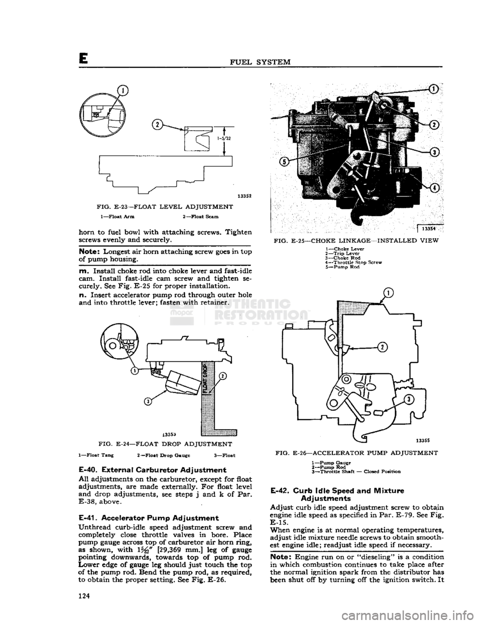
j.
With
air horn assembly inverted, measure the distance from the air horn gasket to top of float
at toe \%£f [27,78 mm.] for standard carburetors
and
\%i [29,36 mm.] for exhaust emission control
equipped carburetors, as shown in Fig. E-23. Use
float level
gauge
J-5127-2. Bend float arm as re
quired
to adjust float level.
k.
With
air horn body held upright, measure dis
tance from gasket to
bottom
of float
pontoon
at outer end. Use a l7/s" [47,625 mm.] float drop
gauge.
Bend float tang, as required, to adjust float
drop.
See Fig. E-24.
I.
Carefully
place air horn body on fuel bowl
body, making certain that the accelerator pump
plunger is properly positioned in the pump well.
Lower
the cover gently, straight down; install air 123
Page 124 of 376
FUEL
SYSTEM
1-5/32
133S2
FIG.
E-23—FLOAT
LEVEL
ADJUSTMENT
l—Float
Arm 2—Float Scam
horn
to fuel bowl with attaching screws. Tighten screws evenly and securely.
Note:
Longest air horn attaching screw
goes
in top
of pump housing.
m.
Install
choke rod into choke lever and fast-idle
cam.
Install
fast-idle cam screw and tighten se
curely.
See Fig. E-25 for proper installation,
n.
Insert accelerator pump rod through outer
hole
and
into throttle lever; fasten with retainer.
A33S3
FIG. E-24—FLOAT DROP ADJUSTMENT
1—Float Tang 2—Float Drop Gauge 3—Float
E-40.
External
Carburetor
Adjustment
All
adjustments on the carburetor, except for float
adjustments, are made externally. For float level
and
drop adjustments, see
steps
j and k of Par.
E-38,
above.
E-41.
Accelerator Pump Adjustment
Unthread
curb-idle speed adjustment screw and completely
close
throttle valves in bore. Place
pump
gauge
across top of carburetor air horn ring,
as shown, with 15^" [29,369 mm.] leg of
gauge
pointing downwards, towards top of pump rod.
Lower
edge
of
gauge
leg should just touch the top
of the pump rod. Bend the pump rod, as required, to obtain the proper setting. See Fig. E-26. ]
13354
FIG.
E-25—CHOKE LINKAGE—INSTALLED VIEW 1—
Choke
Lever
2—
Trip
Lever
3—
Choke
Rod
4—
Throttle
Stop Screw 5—
Pump
Rod
13355
FIG.
E-26—ACCELERATOR
PUMP
ADJUSTMENT 1—
Pump
Gauge 2—
Pump
Rod
3—
Throttle
Shaft — Closed Position
E-42.
Curb
Idle Speed and Mixture
Adjustments
Adjust
curb idle speed adjustment screw to obtain
engine
idle speed as specified in Par. E-79. See Fig.
E-15.
When
engine
is at normal operating temperatures,
adjust
idle mixture
needle
screws to obtain smooth
est
engine
idle; readjust idle speed if necessary.
Note:
Engine run on or "dieseling" is a condition
in
which combustion continues to take place after
the normal ignition spark from the distributor has
been shut off by turning off the ignition switch. It 124
Page 174 of 376
H
ELECTRICAL
SYSTEM
the condenser. Replace the condenser. If there is
no jump to full voltage, overhaul or replace the
distributor.
k.
With the points closed, connect the voltmeter
from
a clean, paint-free
post
on the distributor
body to the negative
post
of the battery. The volt
age drop should be practically zero, a hardly
readable deflection on the voltmeter. If the volt meter registers a
voltage
drop, perform the checks
in
steps
1
and m following.
I.
Check
for
voltage
drop in the battery ground
cable.
Clean
the battery
post,
cable terminals, and contact surface on the bellhousing, or on body if
a
noticeable deflection of the voltmeter occurs,
m.
Check
for any
voltage
drop
between
the dis
tributor
body and a clean, paint-free
spot
on the
cylinder
block. If there is any
voltage
drop, remove
the distributor and clean the mounting surfaces of
distributor
body and cylinder block.
H-5.
SECONDARY
CIRCUIT
If
satisfactory ignition is not obtainable with cor
rect
point gap and tension; satisfactory condenser;
sufficient primary voltage; and correctly cleaned, gapped, and installed spark plugs; the secondary
circiut
should be investigated.
a.
Test the coil.
Bring
the coil up to operating
temperature using the coil heat feature of a coil tester, if available. Refer to the coil tester manu
facturer's
instructions for specific hook-ups for
performing the checks given in
steps
b, c, and d following.
b. Connect the positive lead of the tester to the
battery terminal of the coil primary winding.
Con
nect the tester ground lead to the coil tower. Mea
sure
the resistance of the secondary winding. If the
resistance is more than
20,000
ohms, a fault in the
secondary winding is indicated.
c.
Check
for a grounded secondary by touching the tester ground lead to the coil cover. If resistance
is not over
100,000
ohms, the secondary is grounded
to the cover.
d.
If the secondary winding is satisfactory, mea
sure
the primary current draw in accordance with
the instructions of the
test
equipment manu
facturer.
e.
Check
the secondary circuit for leakage. With the coil primary in the circuit with the breaker unit of the tester, connect a long, high-tension
test
lead
to the coil tower.
Check
the secondary circuit for
leakage by performing the checks given in
steps
f. g, h, and i following.
Note:
In the following
tests,
a slight sparking and
meter deflection
will
usually be
seen
just as contact
is made.
This
is caused by capacitance and
does
not
indicate defective insulation.
f.
Check
distributor cap. Remove the coil lead from the cap and touch the
test
lead to the center contact
inside the cap. If the meter reading drops when the contact is touched or if sparking is seen, a leakage
path is present
between
the center contact and one
of the plug towers.
This
leakage path
will
be in the
form
of a
crack
or carbon track in the cap. Discon nect the spark plug wires from the cap one at a
time and
test
each plug contact with the high-
voltage
lead and with all other plug wires con
nected. Any sparking or meter drop indicates that
a
leakage path exists
between
that particular con
tact and an adjacent one. Testing the adjacent contacts
will
determine which pair is at fault,
g-
Check
distributor rotor. Touch the
test
lead to
the spring contact in the center of the distributor
rotor.
Any leakage in the rotor insulation
between
the contact and the shaft
will
cause a drop in the meter reading and usually sparking
will
be seen.
h.
Check
spark plug wires. Disconnect the spark
plug wires from the plugs and
test
the plug terminal of each. The meter reading should not drop below
the open secondary value (value before making contact). If it
does
or if a large spark occurs when
the
test
lead and the plug wire are separated, there
is a break in the insulation on that wire.
i.
Check
the coil tower insulation. Remove the
high-tension
test
lead from the coil tower and touch
the ground lead of the coil tester to several points
around
the base of the tower. Any sparking or deflection of the meter indicates a leakage path in
the tower insulation.
H-6.
Alternator Charging System
All
Jeep
Universal
Series vehicles have, as standard
equipment a 35-amp., 12-volt, negative ground
alternator and a transistorized
voltage
regulator.
For
repairing the alternator, many of its major components are furnished as complete assemblies
including:
complete brush assembly which requires no soldering or unsoldering of leads; two complete
rectifying
diode
assemblies which eliminate the need for removing and replacing individual diodes;
a
complete isolation
diode
assembly; and a rotor assembly complete with shaft,
pole
pieces, field coil,
and
slip rings.
The
transistorized
voltage
regulator is an electronic
switching device. It
senses
the
voltage
appearing at the auxiliary terminal of the alternator and
supplies the necessary field current for maintaining the system
voltage
at the output
terminal.
The out
put current is determined by the battery electrical
load;
such as headlights, heater, etc.
The
transistorized
voltage
regulator is a sealed unit,
has no adjustments, and must be replaced as a
complete unit.
H-7.
Starting System
The
operation of the starter motor is controlled by
the ignition switch. The starter is made up of a
frame,
field coil, armature, and brushes.
The
starter solenoid electrically
closes
the circuit
between
the battery and the starter motor. When the ignition key is turned to its extreme right, the
solenoid is energized and
closes
the battery-to- starter-motor circuit.
Note:
All Jeep Universal Series vehicles have the
starter
solenoid switch secured to the starter motor
assembly. The Hurricane F4 and Dauntless V-6
engine
Prestolite starter drive is of the inertia type
(rexr
continued on
page
176) 174
Page 181 of 376
'Jeep'
UNIVERSAL
SERIES SERVICE
MANUAL
H
12955
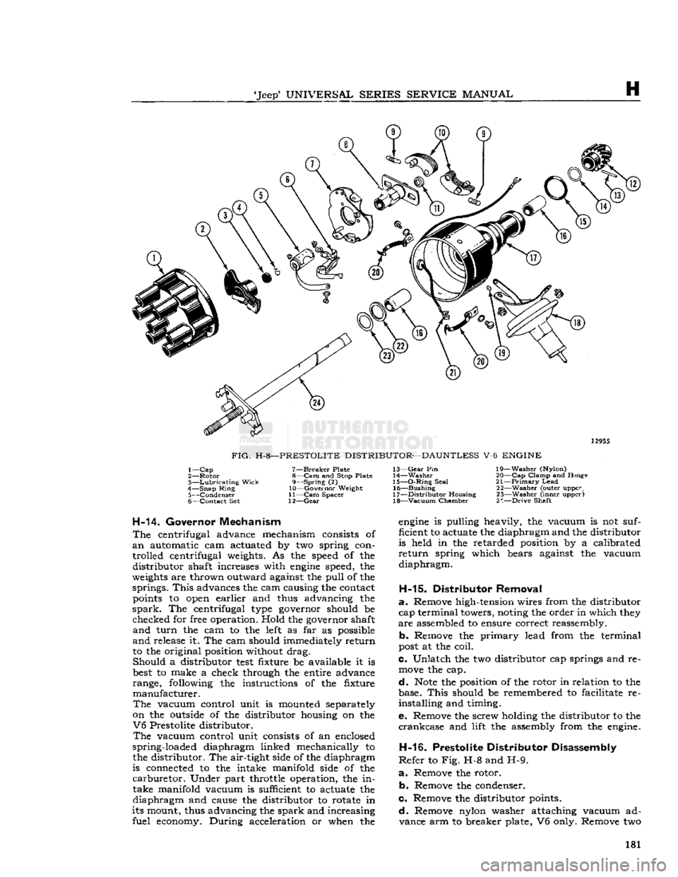
FIG.
H-8—PRESTOLITE
DISTRIBUTOR—DAUNTLESS V-6 ENGINE 1—
Cap
2—
Rotor
3—
Lubricating
Wick
4—
Snap
Ring
5—
Condenser
6—
Contact
Set 7—
Breaker
Plate
8—
Cam
and Stop Plate 9—
Spring
(2)
10—
Governor
Weight
11— Cam
Spacer
12—
Gear
13—
Gear
Pin
14—
Washer
15—
O-Ring
Seal
16—
Bushing
17—
Distributor
Housing 18—
Vacuum
Chamber
19—
Washer
(Nylon)
20—
—Cap
Clamp
and Rings
21—
—Primary
Lead
22—
Washer
(outer upper,
23—
Washer
(inner upper)
2".—Drive
Shaft
H-14. Governor Mechanism
The
centrifugal advance mechanism consists of
an
automatic cam actuated by two spring con
trolled centrifugal weights. As the
speed
of the distributor shaft increases with
engine
speed, the
weights
are thrown outward against the pull of the springs.
This
advances the cam causing the contact
points
to
open
earlier and thus advancing the
spark.
The centrifugal
type
governor should be checked for free operation. Hold the governor shaft
and
turn the cam to the
left
as far as possible
and
release it. The cam should immediately return to the original position without drag. Should a distributor
test
fixture be available it is
best
to make a check through the entire advance
range, following the instructions of the fixture manufacturer.
The
vacuum control unit is mounted separately
on the
outside
of the distributor housing on the
V6
Prestolite distributor.
The
vacuum control unit consists of an enclosed
spring-loaded diaphragm linked mechanically to the distributor. The air-tight side of the diaphragm
is connected to the intake manifold side of the
carburetor.
Under part throttle operation, the intake manifold vacuum is sufficient to actuate the
diaphragm and cause the distributor to rotate in
its mount, thus advancing the spark and increasing fuel
economy.
During acceleration or when the
engine
is pulling heavily, the vacuum is not suf
ficient to actuate the diaphragm and the distributor
is held in the retarded position by a calibrated
return
spring which bears against the vacuum
diaphragm.
H-15.
Distributor Removal
a.
Remove high-tension wires from the distributor cap terminal towers, noting the order in which
they
are
assembled to ensure correct reassembly.
b. Remove the primary lead from the terminal
post
at the coil.
c. Unlatch the two distributor cap springs and re
move
the cap.
d.
Note
the position of the rotor in relation to the
base.
This
should be remembered to facilitate re installing and timing.
e. Remove the screw holding the distributor to the
crankcase
and lift the assembly from the
engine.
H-16.
Prestolite Distributor Disassembly
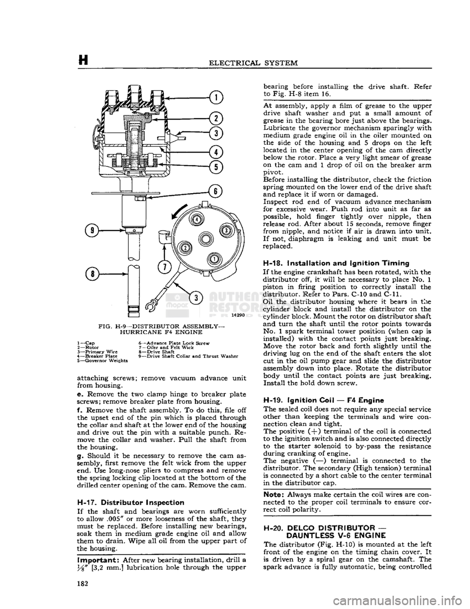
Refer
to Fig. H-8 and H-9.
a.
Remove the rotor. b. Remove the condenser.
c. Remove the distributor points.
d.
Remove nylon washer attaching vacuum advance arm to breaker plate, V6 only. Remove two 181
Page 182 of 376
H
ELECTRICAL
SYSTEM
FIG.
H-9—DISTRIBUTOR ASSEMBLY- HURRICANE F4 ENGINE 1—
Cap
6—Advance Plate
Lock
Screw
2—
Rotor
7—Oiler and
Felt
Wick
3—
Primary
Wire
8—Drive Shaft
4—
Breaker
Plate 9—Drive Shaft
Collar
and
Thrust
Washer 5—
Governor
Weights
attaching screws; remove vacuum advance unit
from housing.
e. Remove the two clamp
hinge
to breaker plate
screws; remove breaker plate from housing.
f. Remove the shaft assembly. To do this, file off
the upset end of the pin which is placed through
the collar and shaft at the lower end of the housing
and
drive out the pin with a suitable punch. Re
move
the collar and washer.
Pull
the shaft from
the housing.
g. Should it be necessary to remove the cam as
sembly, first remove the
felt
wick from the upper
end. Use
long-nose
pliers to compress and remove the spring locking clip located at the
bottom
of the
drilled
center opening of the cam. Remove the cam.
H-17.
Distributor Inspection
If
the shaft and bearings are worn sufficiently
to allow .005" or more
looseness
of the shaft,
they
must be replaced. Before installing new bearings,
soak them in medium grade
engine
oil and allow
them to
drain.
Wipe all oil from the upper part of
the housing.
Important:
After new bearing installation,
drill
a
y%"
[3,2 mm.] lubrication
hole
through the upper bearing
before
installing the drive shaft. Refer
to Fig. H-8 item 16.
At
assembly, apply a film of grease to the upper
drive
shaft washer and put a small amount of
grease in the bearing bore just
above
the bearings.
Lubricate
the governor mechanism sparingly with
medium grade
engine
oil in the oiler mounted on
the side of the housing and 5 drops on the
left
located in the center opening of the cam directly
below
the rotor. Place a very light smear of grease
on the cam and 1 drop of oil on the breaker arm pivot.
Before installing the distributor, check the friction
spring
mounted on the lower end of the drive shaft
and
replace it if worn or damaged. Inspect rod end of vacuum advance mechanism
for
excessive
wear. Push rod
into
unit as far as
possible, hold finger tightly over nipple, then release rod. After about 15 seconds, remove finger
from nipple, and
notice
if air is drawn
into
unit.
If
not, diaphragm is leaking and unit must be
replaced.
H-18.
Installation and Ignition
Timing
If
the
engine
crankshaft has
been
rotated, with the
distributor off, it
will
be necessary to place No. 1
piston in firing position to correctly install the distributor. Refer to
Pars.
C-10 and
C-ll. Oil
the distributor housing where it bears in the
cylinder
block and install the distributor on the
cylinder
block. Mount the rotor on distributor shaft
and
turn
the shaft until the rotor
points
towards No. 1
spark
terminal tower position (when cap is installed) with the contact
points
just breaking. Move the rotor back and forth slightly until the
driving
lug on the end of the shaft enters the
slot
cut in the oil pump gear and slide the distributor
assembly down
into
place. Rotate the distributor
body
until the contact
points
are just breaking.
Install
the hold down screw.
H-19.
Ignition
Coil
— F4 Engine
The
sealed coil
does
not require any special service
other than keeping the terminals and wire con nection clean and tight.
The
positive (+) terminal of the coil is connected
to the ignition switch and is also connected directly
to the starter solenoid to by-pass the resistance
during
cranking of
engine.
The
negative
(—) terminal is connected to the
distributor. The secondary (High tension) terminal
is connected by a short cable to the center terminal
in
the distributor cap.
Note:
Always make certain the coil wires are con
nected to the proper coil terminals to ensure cor
rect coil polarity.
H-20. DELCO DISTRIBUTOR
—
DAUNTLESS
V-6
ENGINE
The
distributor (Fig. H-10) is mounted at the
left
front of the
engine
on the timing chain cover. It
is driven by a
spiral
gear on the camshaft. The
spark
advance is fully automatic, being controlled 182