clock JEEP RENEGADE 2018 Owner handbook (in English)
[x] Cancel search | Manufacturer: JEEP, Model Year: 2018, Model line: RENEGADE, Model: JEEP RENEGADE 2018Pages: 356, PDF Size: 6.11 MB
Page 43 of 356
Additional heater(where provided)
The additional heater ensures more rapid
passenger compartment heating.
It activates in cold weather conditions, if
the following conditions occur:
outside temperature low;engine coolant temperature low;engine on;fan speed set at least to first speed;air temperature knob turned
completely clockwise to red section.
The heater is switched off when at least
one of the conditions above is no longer
verified.
NOTE The power of the electric heater is
modulated according to the battery
voltage.
41
Page 49 of 356
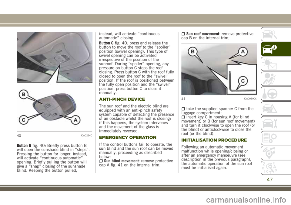
Button Bfig. 40: Briefly press button B
will open the sunshade blind in “steps”.
Pressing the button for longer, instead,
will activate “continuous automatic”
opening. Briefly pulling the button will
give a “snap” closing of the sunshade
blind. Keeping the button pulled,instead, will activate “continuous
automatic” closing.
Button Cfig. 40: press and release the
button to move the roof to the “spoiler”
position (swivel opening). This type of
swivel opening can be activated
irrespective of the position of the
sunroof. During “spoiler” opening, any
pressure on button C stops the roof
closing. Press button C with the roof fully
closed to open the roof to the “swivel”
position. If the roof is positioned between
the fully open position and the “swivel”
position, press button C to close it
manually.
ANTI-PINCH DEVICE
The sun roof and the electric blind are
equipped with an anti-pinch safety
system capable of detecting the presence
of an obstacle whilst the roof is closing:
if this happens, the system intervenes
and the movement of the glass is
immediately reversed.
EMERGENCY OPERATION
If the control buttons fail to operate, the
sun blind and the sun roof can be moved
manually, proceeding as described
below:
Sun blind movement: remove protective
cap A fig. 41 on the internal trim;
Sun roof movement: remove protective
cap B on the internal trim;
take the supplied spanner C from the
luggage compartment;
insert key C in housing A (for blind
movement) or B (for sun roof movement)
and turn it clockwise to open the roof (or
the blind) or anticlockwise to close the
roof (or the blind).
INITIALISATION PROCEDURE
Following an automatic movement
malfunction while opening/closing or
after an emergency manoeuvre (see
description in the previous paragraph),
the automatic operation of the sun roof
must be initialised again.
40J0A0224C
41J0A00390C
47
Page 53 of 356
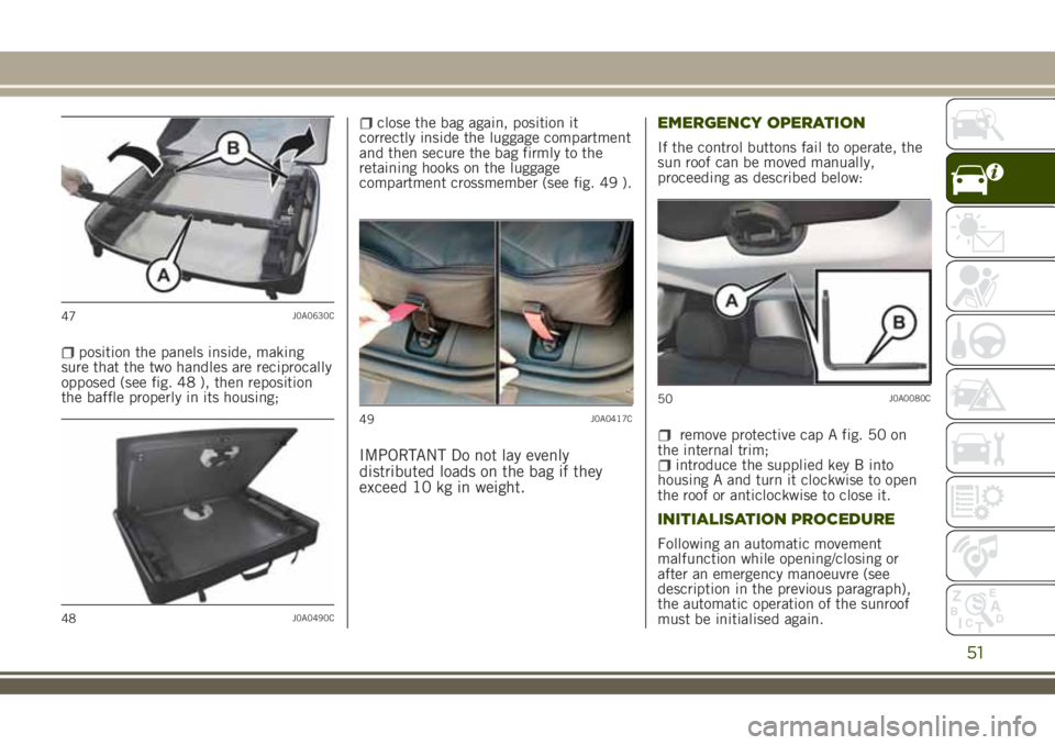
position the panels inside, making
sure that the two handles are reciprocally
opposed (see fig. 48 ), then reposition
the baffle properly in its housing;
close the bag again, position it
correctly inside the luggage compartment
and then secure the bag firmly to the
retaining hooks on the luggage
compartment crossmember (see fig. 49 ).
IMPORTANT Do not lay evenly
distributed loads on the bag if they
exceed 10 kg in weight.EMERGENCY OPERATION
If the control buttons fail to operate, the
sun roof can be moved manually,
proceeding as described below:
remove protective cap A fig. 50 on
the internal trim;
introduce the supplied key B into
housing A and turn it clockwise to open
the roof or anticlockwise to close it.
INITIALISATION PROCEDURE
Following an automatic movement
malfunction while opening/closing or
after an emergency manoeuvre (see
description in the previous paragraph),
the automatic operation of the sunroof
must be initialised again.
47J0A0630C
48J0A0490C
49J0A0417C
50J0A0080C
51
Page 58 of 356
IMPORTANT
13)The dimensions of the platform permit
a maximum capacity of distributed weight
of 110 kg on both positions ("0" and "1"):
do not load objects with a higher weight.
VERSION WITH LPG
SYSTEM
(where provided)
29) 30)
14) 15) 16)
INTRODUCTION
The LPG version features two fuel supply
systems: one for petrol and one for LPG.
PASSIVE SAFETY / ACTIVE
SAFETY
Although the LPG system has numerous
safety features, it is advisable to proceed
as follows every time the car is not in use
for a long period or moved in an
emergency as a result of a breakdown or
accident:
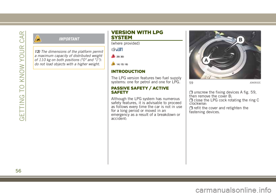
unscrew the fixing devices A fig. 59,
then remove the cover B;
close the LPG cock rotating the ring C
refit the cover and retighten the
fastening devices.
59J0A0932C
56
GETTING TO KNOW YOUR CAR
clockwise:
Page 70 of 356
GEAR SHIFT INDICATOR(where provided)
The Gear Shift Indicator (GSI) system
advises the driver to change gear through
a special indication on the display.
Through the GSI, the driver is informed
that the gear change will allow a
reduction in fuel consumption.
SHIFT UP (
SHIFT) icon on the
display: suggests switching to a higher
gear.
SHIFT DOWN (
SHIFT) icon on the
display: suggests switching to a lower
gear.
The indication in the display remains
until a gear is shifted or the driving
conditions go back to a situation where
gearshifting is not required to improve
consumption.
CONTROL BUTTONS
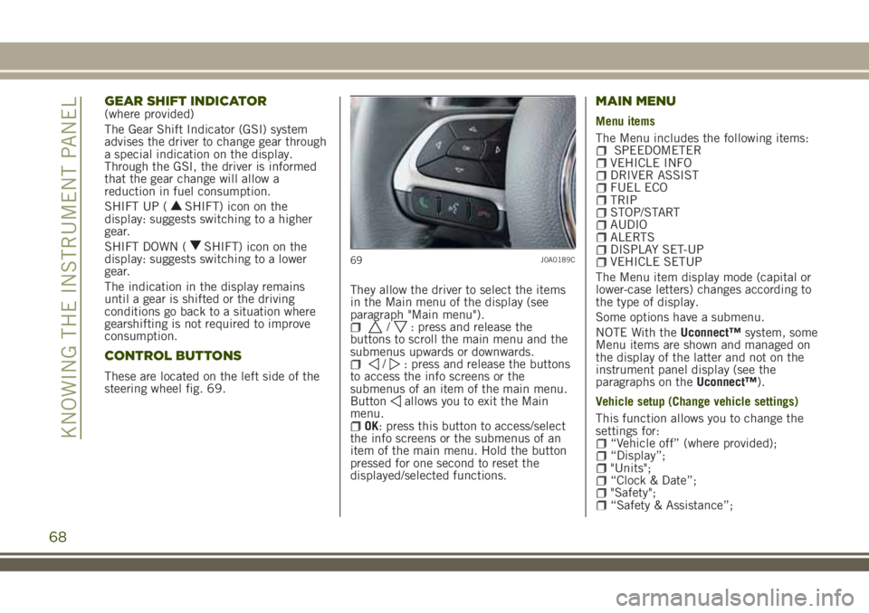
These are located on the left side of the
steering wheel fig. 69.They allow the driver to select the items
in the Main menu of the display (see
paragraph "Main menu").
/: press and release the
buttons to scroll the main menu and the
submenus upwards or downwards.
/: press and release the buttons
to access the info screens or the
submenus of an item of the main menu.
Button
allows you to exit the Main
menu.
OK: press this button to access/select
the info screens or the submenus of an
item of the main menu. Hold the button
pressed for one second to reset the
displayed/selected functions.
MAIN MENU
Menu items
The Menu includes the following items:
SPEEDOMETERVEHICLE INFODRIVER ASSISTFUEL ECOTRIPSTOP/STARTAUDIOALERTSDISPLAY SET-UPVEHICLE SETUP
The Menu item display mode (capital or
lower-case letters) changes according to
the type of display.
Some options have a submenu.
NOTE With theUconnect™system, some
Menu items are shown and managed on
the display of the latter and not on the
instrument panel display (see the
paragraphs on theUconnect™).
Vehicle setup (Change vehicle settings)
This function allows you to change the
settings for:
“Vehicle off” (where provided);“Display”;"Units";“Clock & Date”;"Safety";“Safety & Assistance”;
69J0A0189C
68
KNOWING THE INSTRUMENT PANEL
Page 71 of 356
"Lights";“Doors & Locks”;
Vehicle off
(where provided)
Select "Vehicle off" to switch off the
engine in the event of a fault in the
Keyless Enter-N-Go system, following the
procedure described on the display.
Display
By selecting item "Display" you can
access the settings/information
regarding: "Language", "See phone", "See
navigation".
Units
Select item "Units" to choose the unit of
measurement between: "US" (setting
available only for some markets),
"Metric", "Personalised".
Clock & Date
Select item "Clock & Date" to make the
following adjustments: "Set time", "Time
format", "Set date".
Safety
Select item "Security" to make the
following adjustments: "Passenger
AIRBAG", "Speed beep", "Seatbelt beep",
"Hill Start Assist".
The "Passenger AIRBAG" function is used
to activate/deactivate the front passengerside airbag.Passenger protection on: theONLED turns on continuously on the
instrument panel.Passenger protection
off: the
OFFLED turns on continuously
on the instrument panel.
Safety & Assistance
For possible adjustments see paragraph
Uconnect™in chapter "Multimedia".
Lights
Select item "Lights" to make the
following adjustments: "Interior lights",
"Follow me", "Headlights while opening",
"Headlight sensor", "Auto high beams",
"Daytime Lights", "Cornering lights".
Doors & Locks
Select item "Doors & Locks" to make the
following adjustments: "Autoclose",
"Unlock doors/exit", "Lights when
closing", "Horn when closing", "Remote
start-up horn", "Remotely unlock door"
(versions without Passive Entry), "Unlock
door" (versions with Passive Entry),
"Passive Entry".Versions with reconfigurable multifunction
display
On versions equipped with reconfigurable
multifunction display only the following
items are available: "Display" (only items
"See phone" and "See navigation" can be
selected), "Security" and "Safety &
Assistance" (only item "Buzzer volume"
can be selected). All other items will be
shown and managed on theUconnect™
system display.
69
Page 184 of 356
in which the vehicle is sold. If you are
in a different country, find out what
type of adaptor is used there.
IMPORTANT Before refuelling with
LPG, the qualified personnel must
make sure that the adapter is correctly
screwed onto the filler.
IMPORTANT Look after the LPG
adapter carefully so that it does not get
damaged.
IMPORTANT Only use LPG for motor
vehicles.
IMPORTANT Only use the adapter
supplied with the vehicle as it is
equipped with a dedicated fuel
pre-filter.
REFUELLING PROCEDURE
Opening the flap
To refuel proceed as follows:
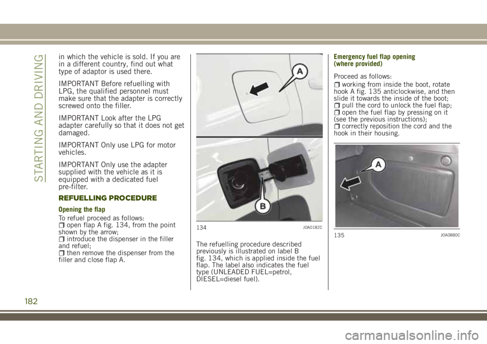
open flap A fig. 134, from the point
shown by the arrow;
introduce the dispenser in the filler
and refuel;
then remove the dispenser from the
filler and close flap A.The refuelling procedure described
previously is illustrated on label B
fig. 134, which is applied inside the fuel
flap. The label also indicates the fuel
type (UNLEADED FUEL=petrol,
DIESEL=diesel fuel).Emergency fuel flap opening
Proceed as follows:
working from inside the boot, rotate
hook A fig. 135 anticlockwise, and then
slide it towards the inside of the boot;
pull the cord to unlock the fuel flap;open the fuel flap by pressing on it
(see the previous instructions);
correctly reposition the cord and the
hook in their housing.
134J0A0182C
135J0A0880C
182
STARTING AND DRIVING
(where provided)
Page 198 of 356
REPLACING AN EXTERNAL BULB
Front upper light group (halogen high/low
beams)
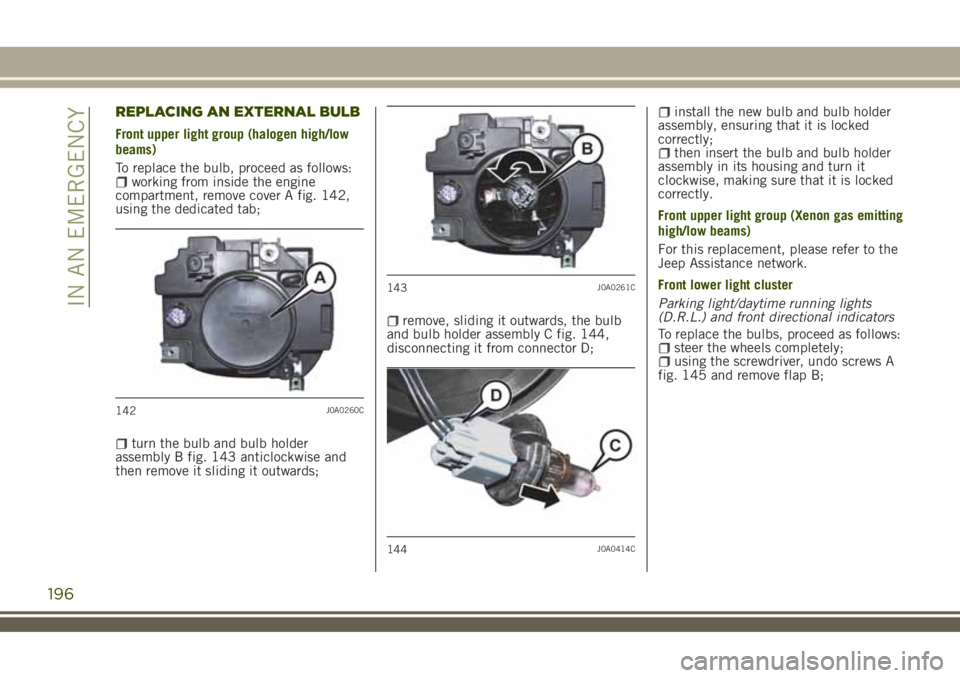
To replace the bulb, proceed as follows:
working from inside the engine
compartment, remove cover A fig. 142,
using the dedicated tab;
turn the bulb and bulb holder
assembly B fig. 143 anticlockwise and
then remove it sliding it outwards;
remove, sliding it outwards, the bulb
and bulb holder assembly C fig. 144,
disconnecting it from connector D;
install the new bulb and bulb holder
assembly, ensuring that it is locked
correctly;
then insert the bulb and bulb holder
assembly in its housing and turn it
clockwise, making sure that it is locked
correctly.
Front upper light group (Xenon gas emitting
high/low beams)
For this replacement, please refer to the
Jeep Assistance network.
Front lower light cluster
Parking light/daytime running lights
(D.R.L.) and front directional indicators
To replace the bulbs, proceed as follows:
steer the wheels completely;using the screwdriver, undo screws A
fig. 145 and remove flap B;
142J0A0260C
143J0A0261C
144J0A0414C
196
IN AN EMERGENCY
Page 199 of 356

remove electrical connectors C
fig. 146;
turn anticlockwise (on the left device)
or clockwise (on the right device) and
remove the bulb and bulb holder
assemblies fig. 147: D = side
lights/daytime running lights (DRLs), E =
direction indicators;
replace the burnt bulb: to extract it,
press lightly on it (1 fig. 148 ) and at the
same time turn it counter-clockwise (2);
insert the new bulb, by pressing it
fig. 148 and turning it clockwise, making
sure that it locks correctly;
then insert the bulb and bulb holder
assemblies in their respective housings
and turn them anticlockwise (right side)
and clockwise (left side), ensuring that
they are locked correctly;
reconnect the electrical connectors;finally, refit flap B fig. 145, fully
tightening fixing screws A.
Front fog lights
To replace the bulbs, proceed as follows:
steer the wheels completely;using the screwdriver, undo screws A
fig. 149 and remove flap B;
145J0A0211C
146J0A0306C
147J0A0263C
148J0A0264C
197
Page 200 of 356
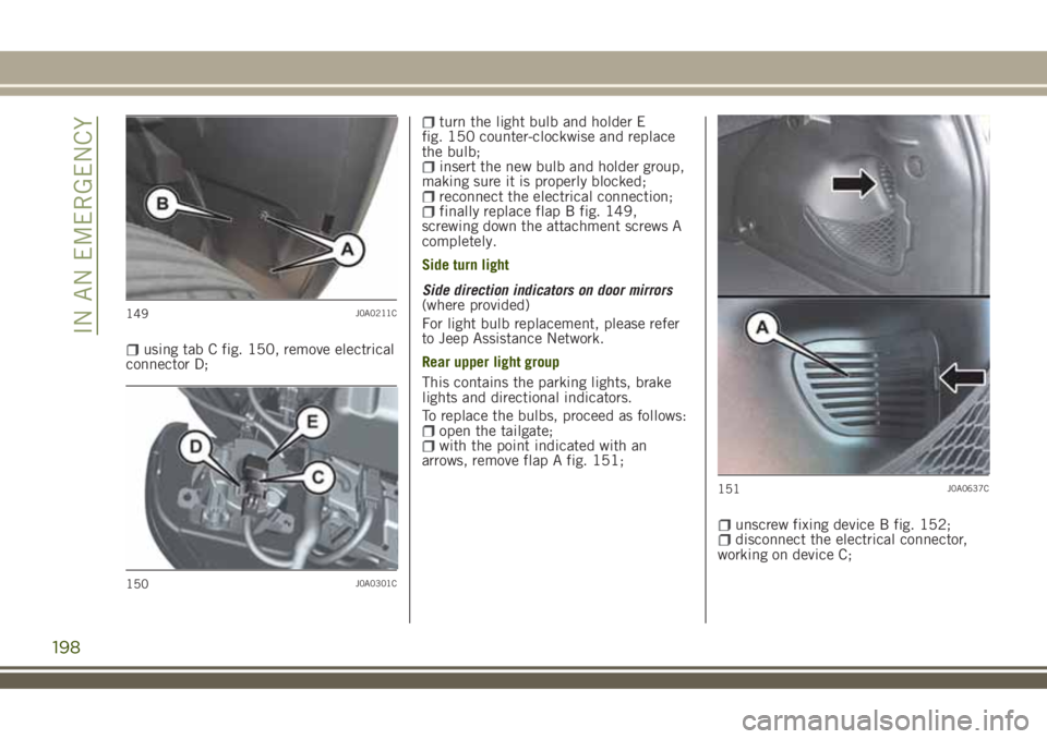
using tab C fig. 150, remove electrical
connector D;
turn the light bulb and holder E
fig. 150 counter-clockwise and replace
the bulb;
insert the new bulb and holder group,
making sure it is properly blocked;
reconnect the electrical connection;finally replace flap B fig. 149,
screwing down the attachment screws A
completely.
Side turn light
Side direction indicators on door mirrors
(where provided)
For light bulb replacement, please refer
to Jeep Assistance Network.
Rear upper light group
This contains the parking lights, brake
lights and directional indicators.
To replace the bulbs, proceed as follows:
open the tailgate;with the point indicated with an
arrows, remove flap A fig. 151;
unscrew fixing device B fig. 152;disconnect the electrical connector,
working on device C;
149J0A0211C
150J0A0301C
151J0A0637C
198
IN AN EMERGENCY