torque KIA CARNIVAL 2007 Workshop Manual
[x] Cancel search | Manufacturer: KIA, Model Year: 2007, Model line: CARNIVAL, Model: KIA CARNIVAL 2007Pages: 1575, PDF Size: 44.86 MB
Page 564 of 1575
INSTALLATION
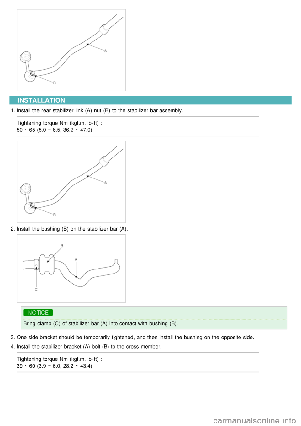
1.Install the rear stabilizer link (A) nut (B) to the stabilizer bar assembly.
Tightening torque Nm (kgf.m, lb - ft) :
50 ~ 65 (5.0 ~ 6.5, 36.2 ~ 47.0)
2.Install the bushing (B) on the stabilizer bar (A).
Bring clamp (C) of stabilizer bar (A) into contact with bushing (B).
3. One side bracket should be temporarily tightened, and then install the bushing on the opposite side.
4. Install the stabilizer bracket (A) bolt (B) to the cross member.
Tightening torque Nm (kgf.m, lb - ft) :
39 ~ 60 (3.9 ~ 6.0, 28.2 ~ 43.4)
Page 565 of 1575
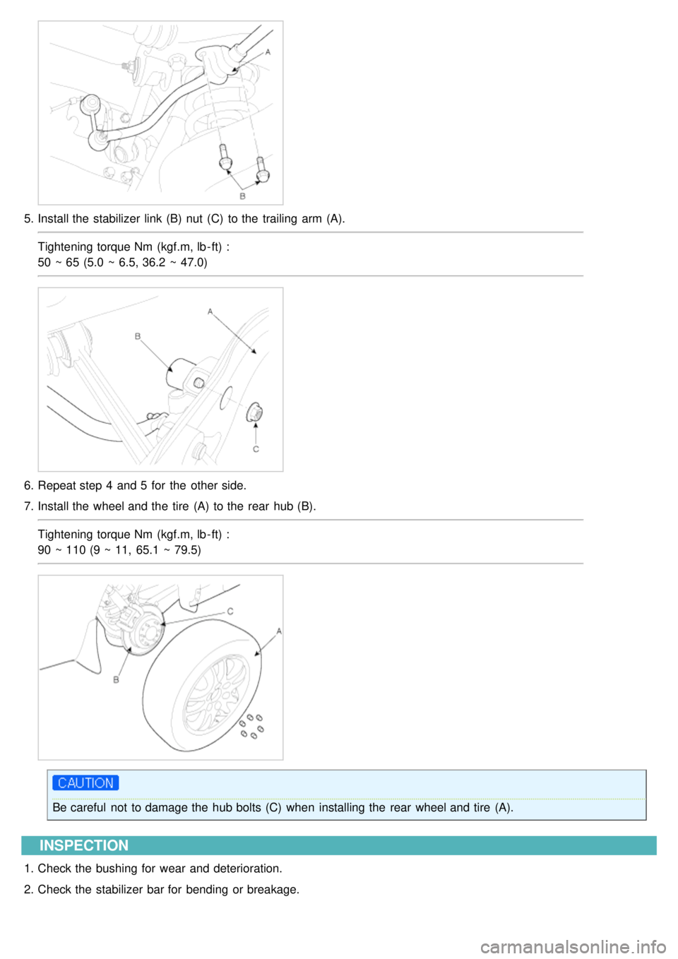
5.Install the stabilizer link (B) nut (C) to the trailing arm (A).
Tightening torque Nm (kgf.m, lb - ft) :
50 ~ 65 (5.0 ~ 6.5, 36.2 ~ 47.0)
6.Repeat step 4 and 5 for the other side.
7. Install the wheel and the tire (A) to the rear hub (B).
Tightening torque Nm (kgf.m, lb - ft) :
90 ~ 110 (9 ~ 11, 65.1 ~ 79.5)
Be careful not to damage the hub bolts (C) when installing the rear wheel and tire (A).
INSPECTION
1.Check the bushing for wear and deterioration.
2. Check the stabilizer bar for bending or breakage.
Page 566 of 1575
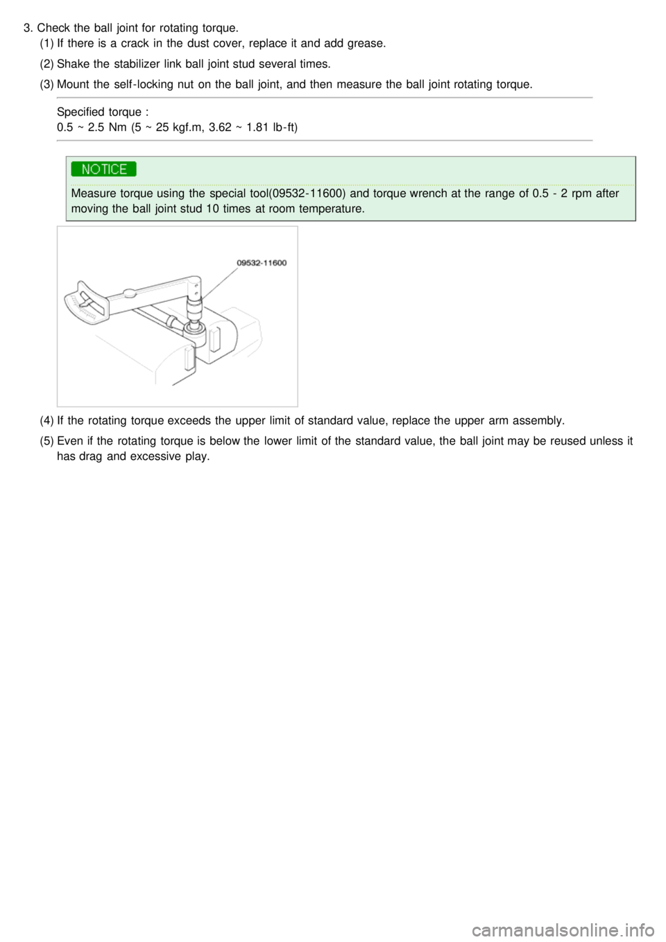
3.Check the ball joint for rotating torque.
(1) If there is a crack in the dust cover, replace it and add grease.
(2) Shake the stabilizer link ball joint stud several times.
(3) Mount the self - locking nut on the ball joint, and then measure the ball joint rotating torque.
Specified torque :
0.5 ~ 2.5 Nm (5 ~ 25 kgf.m, 3.62 ~ 1.81 lb - ft)
Measure torque using the special tool(09532- 11600) and torque wrench at the range of 0.5 - 2 rpm after
moving the ball joint stud 10 times at room temperature.
(4)If the rotating torque exceeds the upper limit of standard value, replace the upper arm assembly.
(5) Even if the rotating torque is below the lower limit of the standard value, the ball joint may be reused unless it
has drag and excessive play.
Page 572 of 1575
2007 > 2.7L V6 GASOLINE >
WHEEL ALIGNMENT
When using commercially available computerized four wheel alignment equipment (caster, camber, toe) to inspect the
front wheel alignment, always position the car on a level surface with the front wheels facing straight ahead.
Prior to inspection, make sure that the front suspension and steering system are in normal operating condition and
that the wheels and tires face straight ahead and the tires are inflated to the specified pressure.
TOE
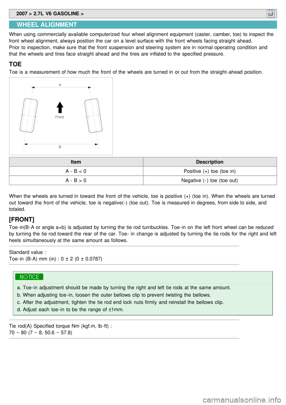
Toe is a measurement of how much the front of the wheels are turned in or out from the straight- ahead position.
Item Description
A - B < 0 Positive (+) toe (toe in)
A - B > 0 Negative ( - ) toe (toe out)
When the wheels are turned in toward the front of the vehicle, toe is positive (+) (toe in). When the wheels are turned
out toward the front of the vehicle, toe is negative(- ) (toe out). Toe is measured in degrees, from side to side, and
totaled.
[FRONT]
Toe- in(B - A or angle a+b) is adjusted by turning the tie rod turnbuckles. Toe- in on the left front wheel can be reduced
by turning the tie rod toward the rear of the car. Toe- in change is adjusted by turning the tie rods for the right and left
heels simultaneously at the same amount as follows.
Standard value :
Toe- in (B- A) mm (in) : 0 ± 2 (0 ± 0.0787)
a. Toe- in adjustment should be made by turning the right and left tie rods at the same amount.
b. When adjusting toe - in, loosen the outer bellows clip to prevent twisting the bellows.
c. After the adjustment, tighten the tie rod end lock nuts firmly and reinstall the bellows clip.
d. Adjust each toe - in to be the range of ±1mm.
Tie rod(A) Specified torque Nm (kgf.m, lb - ft) :
70 ~ 80 (7 ~ 8, 50.6 ~ 57.8)
Page 573 of 1575
![KIA CARNIVAL 2007 Workshop Manual [REAR]
Standard value :
Toe- in (B- A) mm (in) : 2.6 ± 2 (0.1024 ± 0.0787)
Adjust the toe - in by turning the cambolt of the assist arm.
Left cambolt : Clockwise → toe - in
Right camb KIA CARNIVAL 2007 Workshop Manual [REAR]
Standard value :
Toe- in (B- A) mm (in) : 2.6 ± 2 (0.1024 ± 0.0787)
Adjust the toe - in by turning the cambolt of the assist arm.
Left cambolt : Clockwise → toe - in
Right camb](/img/2/57045/w960_57045-572.png)
[REAR]
Standard value :
Toe- in (B- A) mm (in) : 2.6 ± 2 (0.1024 ± 0.0787)
Adjust the toe - in by turning the cambolt of the assist arm.
Left cambolt : Clockwise → toe - in
Right cambolt : Clockwise → toe - out
The variation of toe by a rotation of the cambolt :
About 3.2 mm (0.126 in)
a. Each toe should be within ±1 mm (± 0.039 in).
If the difference between right and left is not within +2mm (0.079 in), repeat adjustment.
b. After adjusting the cambolt, tighten the nut to the specified torque.
Specified torque
90 ~ 120 Nm (9 ~ 12 kgf.m, 65.1 ~ 86.8 lb - ft)
CAMBER
[FRONT]
Camber is the inward or outward tilting of the wheels at the top.
Page 576 of 1575
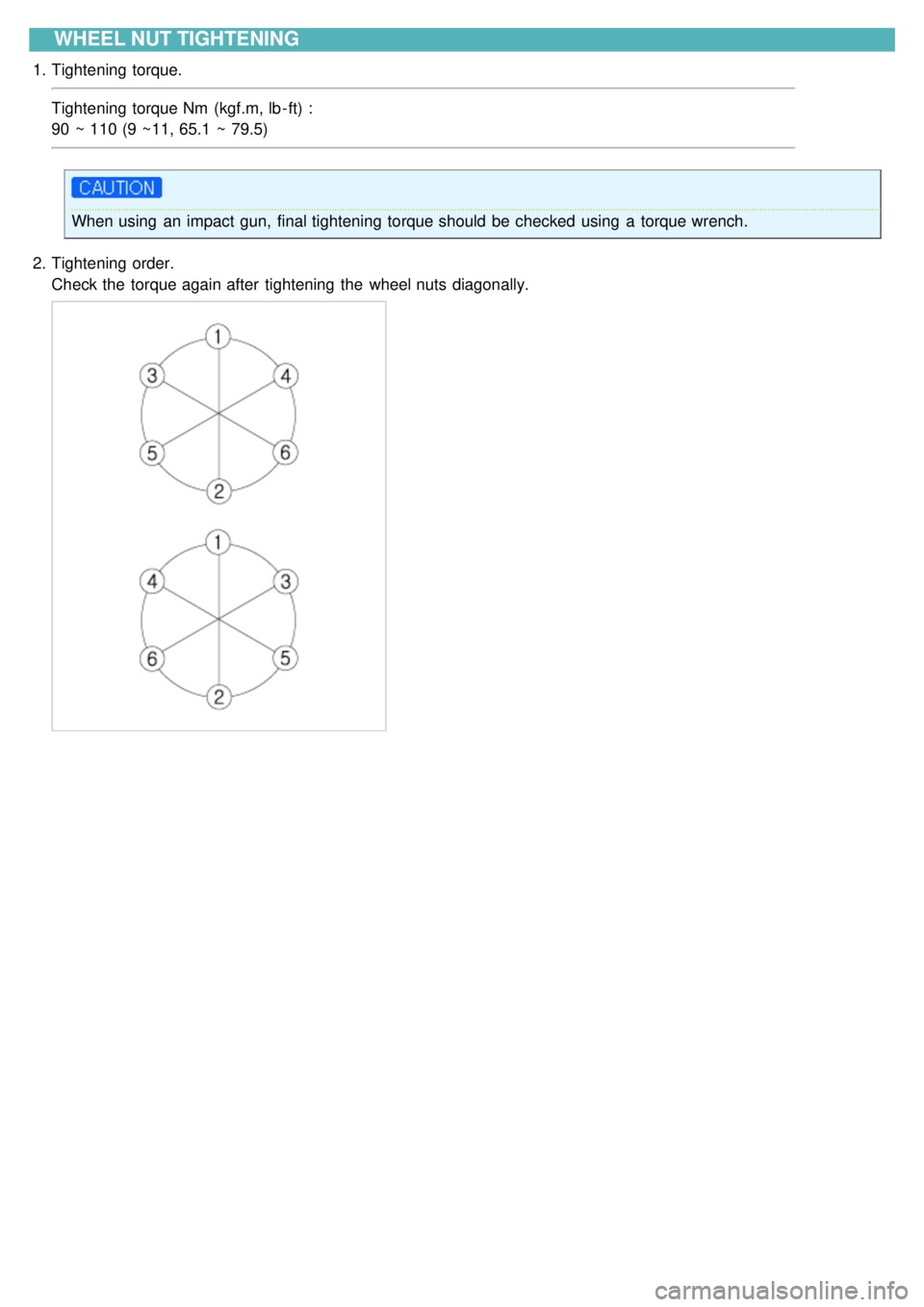
WHEEL NUT TIGHTENING
1.Tightening torque.
Tightening torque Nm (kgf.m, lb - ft) :
90 ~ 110 (9 ~11, 65.1 ~ 79.5)
When using an impact gun, final tightening torque should be checked using a torque wrench.
2. Tightening order.
Check the torque again after tightening the wheel nuts diagonally.
Page 582 of 1575

2007 > 2.7L V6 GASOLINE >
SERVICE ADJUSTMENT PROCEDURE
CHECKING STEERING WHEEL FREE PLAY
1. Start the engine and with the steering wheel in the straight ahead position.
2. Measure the play while turning the steering wheel to the left and right.
Standard value :
Steering wheel free play : 30 mm (1.1 in)
3.If the play exceeds the standard value, inspect the connection between the steering shaft and tie rod ends.
CHECKING STEERING ANGLE
1.Place the front wheel on a turning radius gauge and measure the steering angle.
Standard value
VRS on Inner
38.64 °
Outer 31.78 °
VRS off Inner
41.91 °
Outer 33.54 °
2. If the measured value is not within the standard value, adjust the toe and inspect again.
CHECKING THE TIE ROD END BALL JOINT STARTING TORQUE
1.Disconnect tie rod and knuckle with the special tool (09568- 4A000).
Page 583 of 1575

2.Shake the ball joint stud several times to check for looseness.
Tie rod end ball joint starting torque :
30 kg·cm or less
3.If the starting torque exceeds the upper limit of the standard value, replace the tie rod end.
4. Even if the starting torque is below the lower limit of the standard value, check the play of the ball joint and replace
if necessary.
CHECKING STEERING WHEEL RETURN
1.The force required to turn the steering wheel and the wheel return should be the same for both moderate and sharp
turns.
2. When the steering wheel is turned 90° and held for a couple of seconds while the vehicle is being driven at 20- 30
kph (12- 19 mph), the steering wheel should return at least 20° from its central position when it is released.
If the steering wheel is turned very quickly, steering may be momentarily difficult. This is not a malfunction
because the oil pump output will be somewhat decreased.
Page 586 of 1575
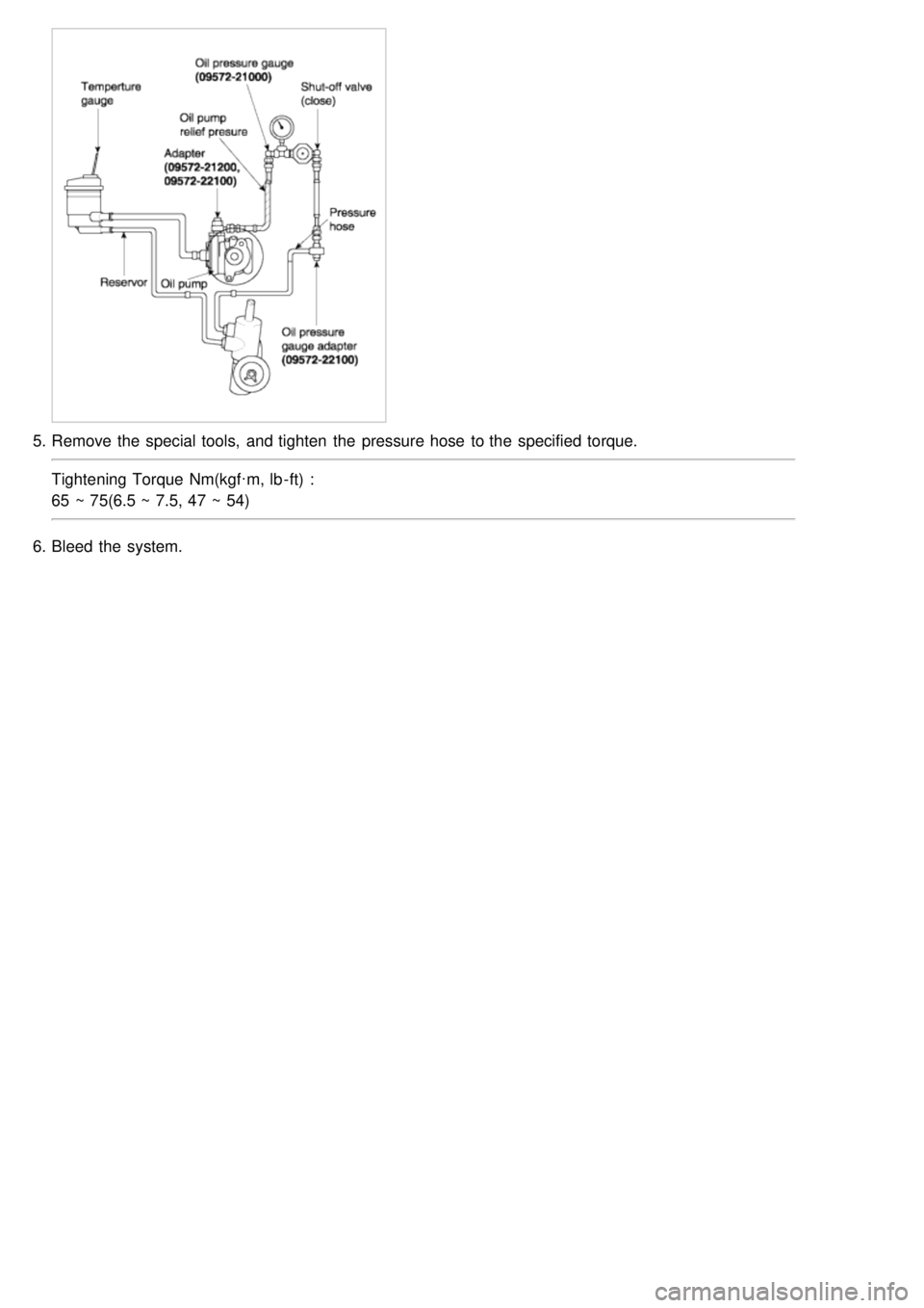
5.Remove the special tools, and tighten the pressure hose to the specified torque.
Tightening Torque Nm(kgf·m, lb - ft) :
65 ~ 75(6.5 ~ 7.5, 47 ~ 54)
6. Bleed the system.
Page 587 of 1575

2007 > 2.7L V6 GASOLINE >
SPECIFICATIONS
Items Specifications
Steering column/ shaft Type
Tilt
Tilt stroke +7°/ - 11.7°
Steering gear Type
Rack & pinion
Rack stroke VRS On
148 mm (5.827 in)
VRS Off 156 mm (6.142 in)
Power steering pump Type
Vane
Diesel Relief pressure
90 kgf/cm²
Discharge 9.6 cc/rev
Gasoline Relief pressure
90 kgf/cm²
Discharge 10.5 cc/rev
SERVICE STANDARD
Items Specifications
Steering wheel free play 30 mm (1.12 in)
Steering angle VRS on
Inner
38.64°
Outer 31.78°
VRS off Inner
41.91°
Outer 33.54°
TIGHTENING TORQUE
Items NmKgf.m Lb- ft
Steering wheel lock nut 40 ~ 504.0 ~ 5.0 29 ~ 36
Steering column mounting bolts and nut 13 ~ 181.3 ~ 1.89.4 ~ 13.0
Bolt connecting steering column to universal
joint 15 ~ 20
1.5 ~ 2.010.8 ~ 14.5
Bolt connecting universal joint to steering gear 13 ~ 181.3 ~ 1.89.4 ~ 13.0
Steering column mounting bolts and nut 13 ~ 181.3 ~ 1.89.4 ~ 13.0
Tie rod end castle nut 35 ~ 453.5 ~ 4.5 25 ~ 33
Front lower arm ball joint assembly bolts 90 ~ 1209.0 ~ 12.0 65 ~ 87
Stabilizer link to strut assembly nut 100 ~ 12010.0 ~ 12.0 72 ~ 87
Rear roll stopper to sub- frame bolts 50 ~ 605.0 ~ 6.0 36 ~ 43
Pressure tube to valve body housing nut 12 ~ 181.2 ~ 1.8 9 ~ 13
Pressure tube to oil pump eye bolt 65 ~ 756.5 ~ 7.5 47 ~ 54
Return tube to valve body housing nut 12 ~ 181.2 ~ 1.8 9 ~ 13
Power steering gear box to sub- frame bots 90 ~ 1109.0 ~ 11.0 65 ~ 80
LUBRICANT
Item Lubricant Quantity
Power steering fluid PSF - 31.1 L