KIA CARNIVAL 2007 Owners Manual
CARNIVAL 2007
KIA
KIA
https://www.carmanualsonline.info/img/2/57045/w960_57045-0.png
KIA CARNIVAL 2007 Owners Manual
Page 518 of 1575
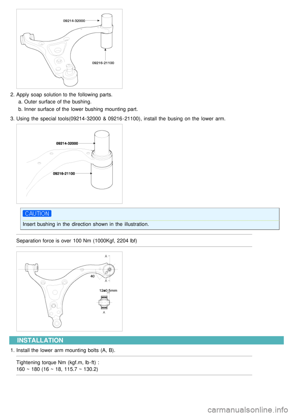
2.Apply soap solution to the following parts.
a. Outer surface of the bushing.
b. Inner surface of the lower bushing mounting part.
3. Using the special tools(09214- 32000 & 09216 - 21100), install the busing on the lower arm.
Insert bushing in the direction shown in the illustration.
Separation force is over 100 Nm (1000Kgf, 2204 lbf)
INSTALLATION
1. Install the lower arm mounting bolts (A, B).
Tightening torque Nm (kgf.m, lb - ft) :
160 ~ 180 (16 ~ 18, 115.7 ~ 130.2)
Page 519 of 1575
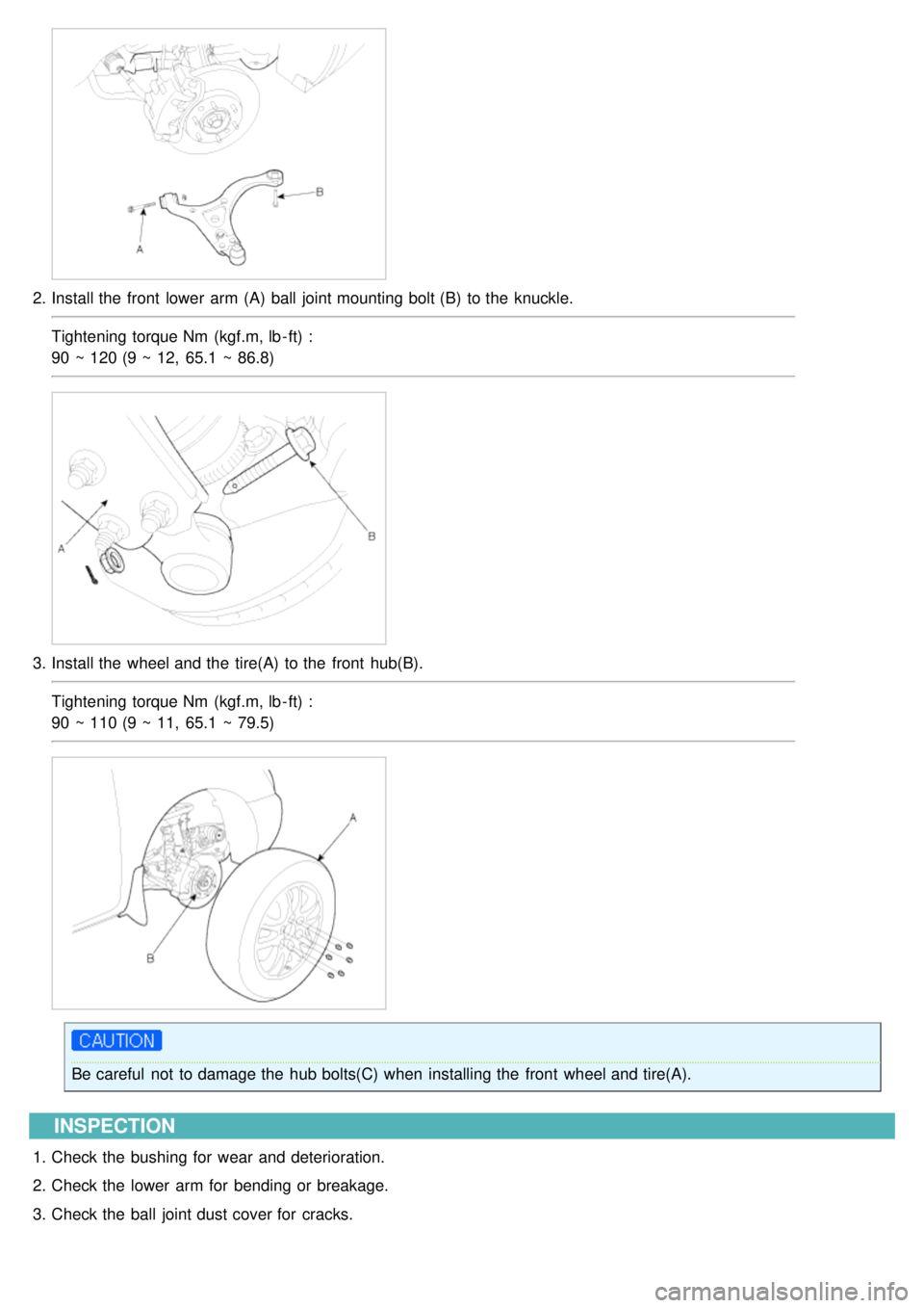
2.Install the front lower arm (A) ball joint mounting bolt (B) to the knuckle.
Tightening torque Nm (kgf.m, lb - ft) :
90 ~ 120 (9 ~ 12, 65.1 ~ 86.8)
3.Install the wheel and the tire(A) to the front hub(B).
Tightening torque Nm (kgf.m, lb - ft) :
90 ~ 110 (9 ~ 11, 65.1 ~ 79.5)
Be careful not to damage the hub bolts(C) when installing the front wheel and tire(A).
INSPECTION
1.Check the bushing for wear and deterioration.
2. Check the lower arm for bending or breakage.
3. Check the ball joint dust cover for cracks.
Page 520 of 1575
4.Check all bolts.
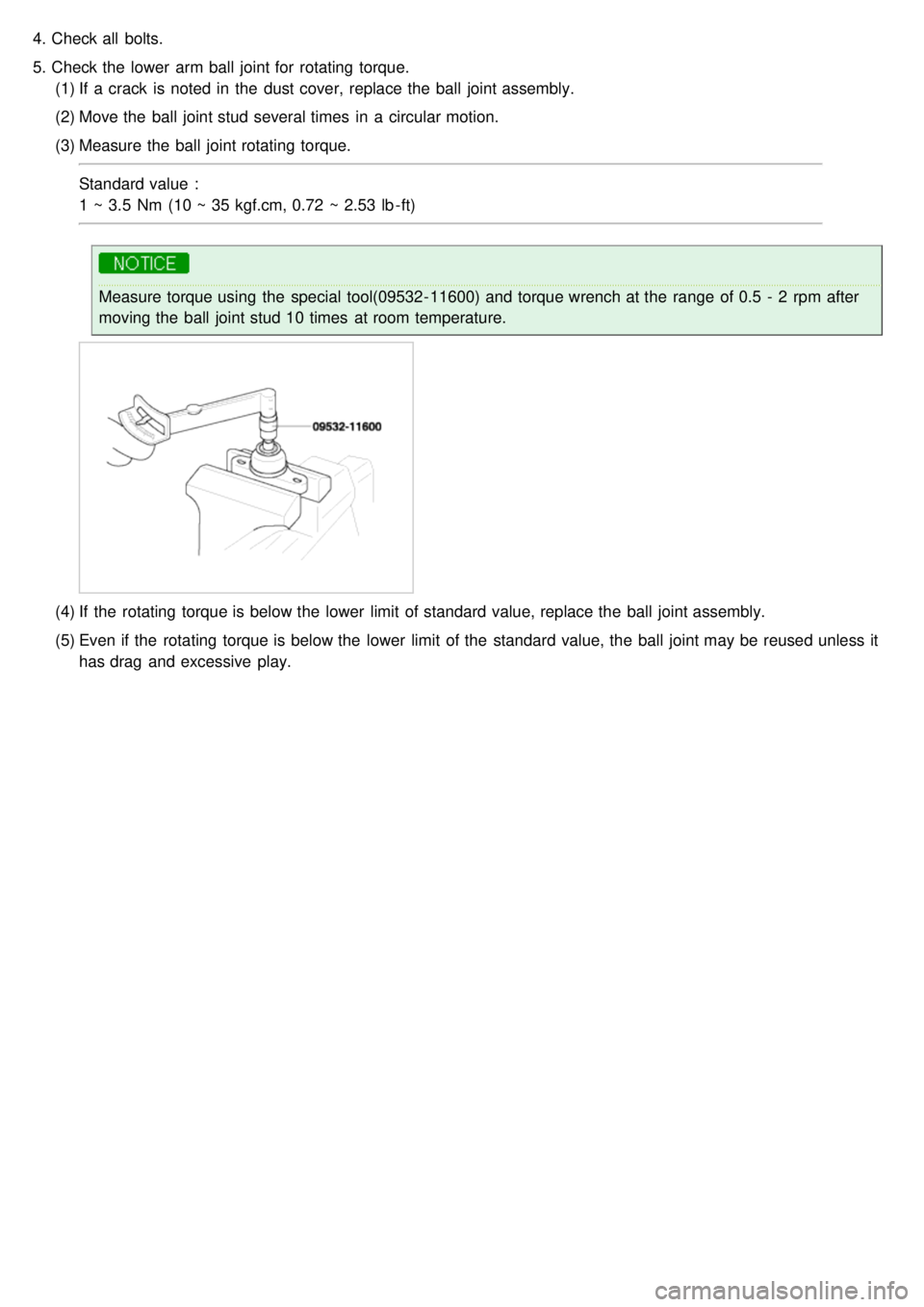
5. Check the lower arm ball joint for rotating torque.
(1) If a crack is noted in the dust cover, replace the ball joint assembly.
(2) Move the ball joint stud several times in a circular motion.
(3) Measure the ball joint rotating torque.
Standard value :
1 ~ 3.5 Nm (10 ~ 35 kgf.cm, 0.72 ~ 2.53 lb - ft)
Measure torque using the special tool(09532- 11600) and torque wrench at the range of 0.5 - 2 rpm after
moving the ball joint stud 10 times at room temperature.
(4)If the rotating torque is below the lower limit of standard value, replace the ball joint assembly.
(5) Even if the rotating torque is below the lower limit of the standard value, the ball joint may be reused unless it
has drag and excessive play.
Page 526 of 1575
INSTALLATION
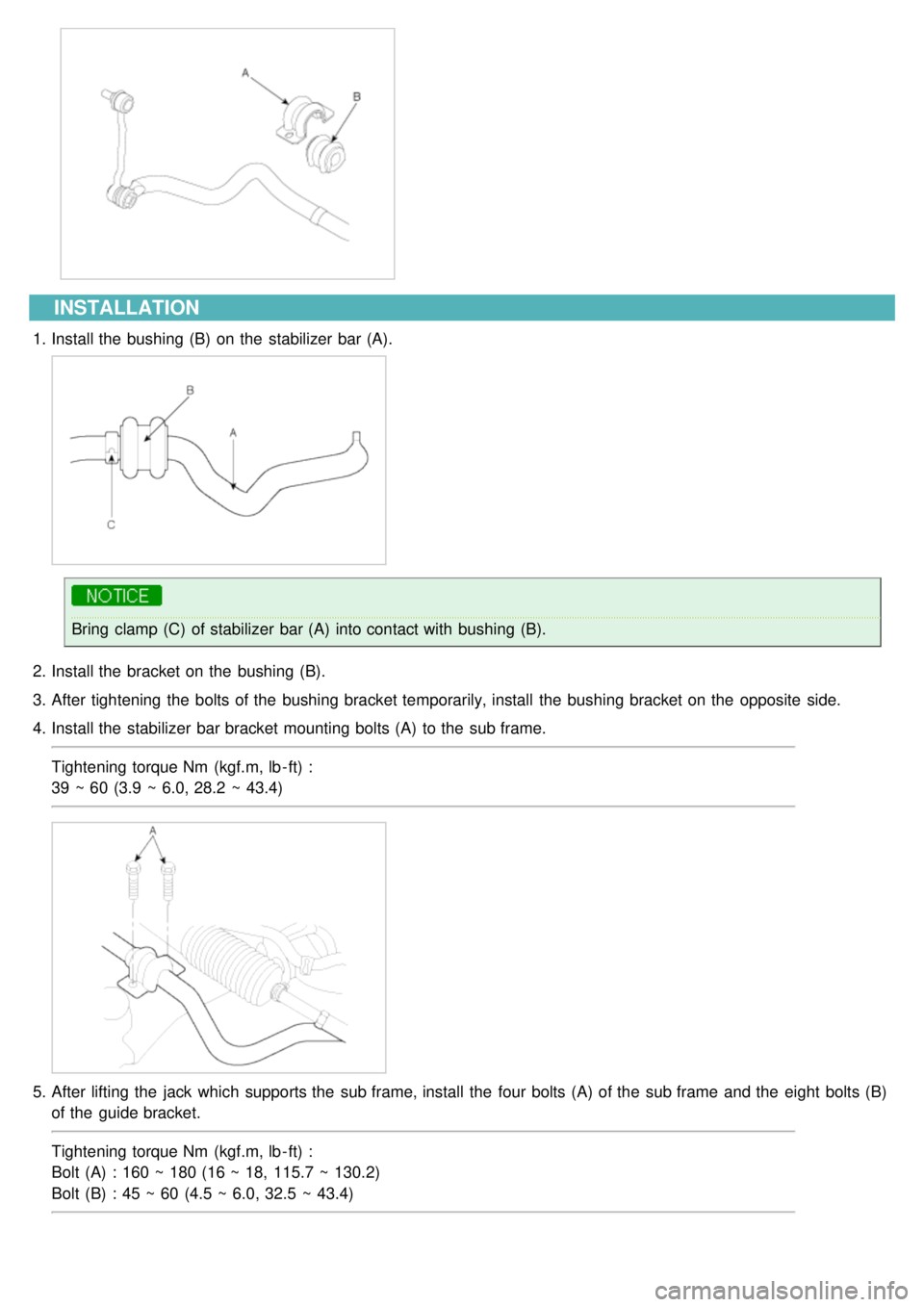
1.Install the bushing (B) on the stabilizer bar (A).
Bring clamp (C) of stabilizer bar (A) into contact with bushing (B).
2. Install the bracket on the bushing (B).
3. After tightening the bolts of the bushing bracket temporarily, install the bushing bracket on the opposite side.
4. Install the stabilizer bar bracket mounting bolts (A) to the sub frame.
Tightening torque Nm (kgf.m, lb - ft) :
39 ~ 60 (3.9 ~ 6.0, 28.2 ~ 43.4)
5.After lifting the jack which supports the sub frame, install the four bolts (A) of the sub frame and the eight bolts (B)
of the guide bracket.
Tightening torque Nm (kgf.m, lb - ft) :
Bolt (A) : 160 ~ 180 (16 ~ 18, 115.7 ~ 130.2)
Bolt (B) : 45 ~ 60 (4.5 ~ 6.0, 32.5 ~ 43.4)
Page 527 of 1575
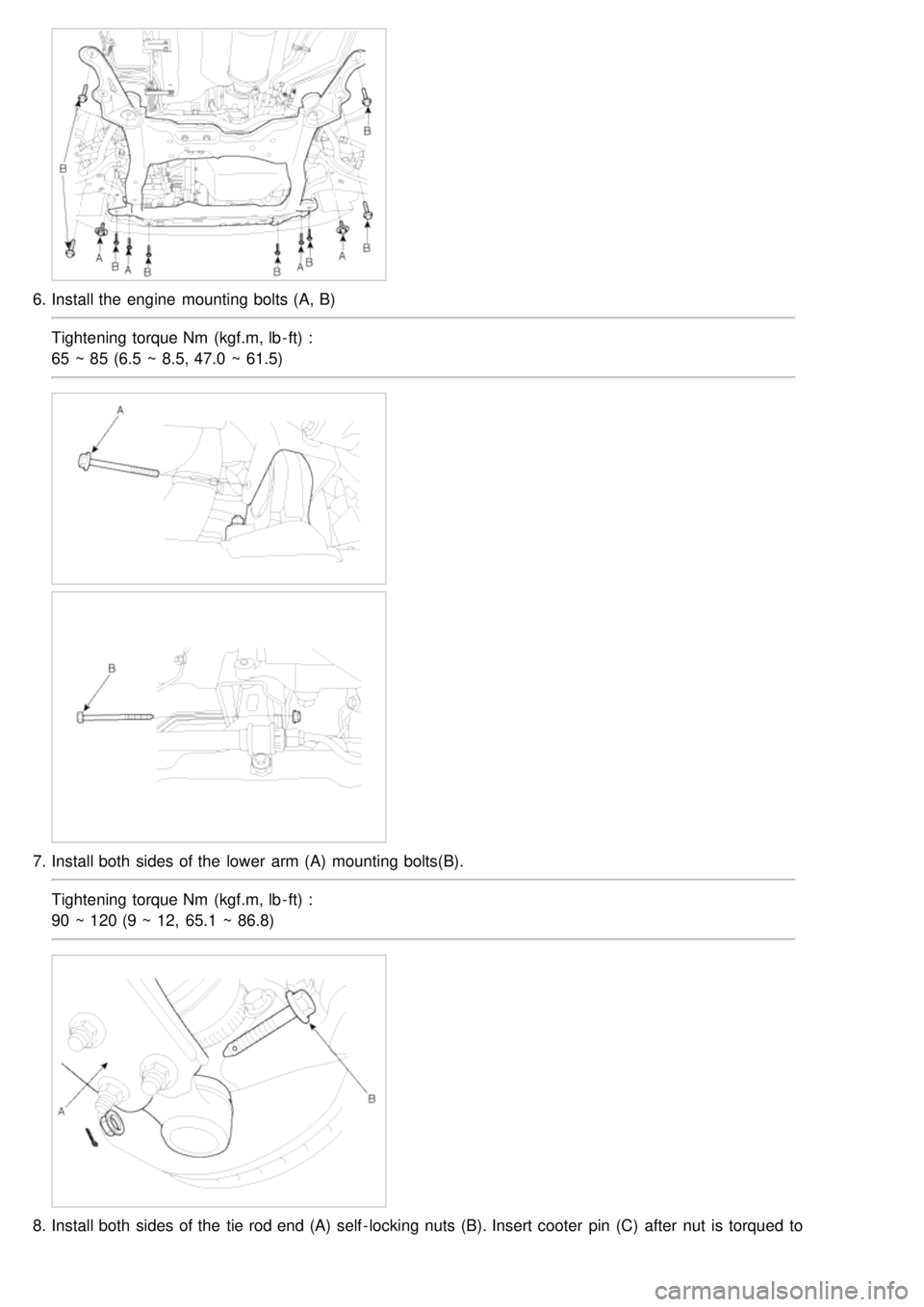
6.Install the engine mounting bolts (A, B)
Tightening torque Nm (kgf.m, lb - ft) :
65 ~ 85 (6.5 ~ 8.5, 47.0 ~ 61.5)
7.Install both sides of the lower arm (A) mounting bolts(B).
Tightening torque Nm (kgf.m, lb - ft) :
90 ~ 120 (9 ~ 12, 65.1 ~ 86.8)
8.Install both sides of the tie rod end (A) self - locking nuts (B). Insert cooter pin (C) after nut is torqued to
specification.
Page 528 of 1575
specification.
Tightening torque Nm (kgf.m, lb - ft) :
65 ~ 80 (6 ~ 8, 43.4 ~ 57.8)
9.Install the front stabilizer link (A) nut (B) to the strut assembly.
Tightening torque Nm (kgf.m, lb - ft) :
100 ~ 120 (10 ~ 12, 72.3 ~ 86.8)
10. Install the wheel and the tire (A) to the front hub (B).
Tightening torque Nm (kgf.m, lb - ft) :
90 ~ 110 (9 ~ 11, 65.1 ~ 79.5)
Be careful not to damage the hub bolts(C) when installing the front wheel and tire(A).
11. Install the connecting bolt (A) between the steering universal joint assembly (B) and the pinion assembly.
Page 529 of 1575

Tightening torque Nm (kgf.m, lb - ft) :
13 ~ 18 (1.3 ~ 1.8, 9.4 ~ 13.0)
After installation, if neccessary, adjust the alignment of the steering wheel and front tires
INSPECTION
1.Check the bushing for wear and deterioration.
2. Check the stabilizer bar for bending or breakage.
3. Check the ball joint for rotating torque.
(1) If there is a crack in the dust cover, replace it and add grease.
(2) Move the stabilizer link ball joint stud several times in a circular motion.
(3) Mount the self - locking nut on the ball joint, and then measure the ball joint rotating torque.
Standard value :
0.5 ~ 2.5 Nm (5 ~ 25 kgf., 0.36 ~ 1.81 lb - ft)
Measure torque using the special tool(09532- 11600) and torque wrench at the range of 0.5 - 2 rpm after
moving the ball joint stud 10 times at room temperature.
(4)If the rotating torque exceeds the upper limit of standard value, replace the upper arm assembly.
(5) Even if the rotating torque is below the lower limit of the standard value, the ball joint may be reused unless it
has drag and excessive play.
Page 535 of 1575
INSTALLATION
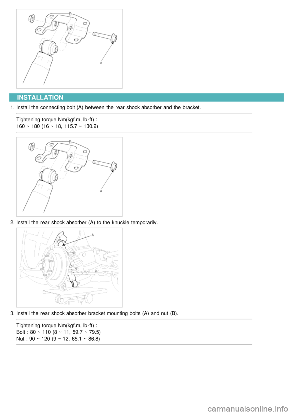
1.Install the connecting bolt (A) between the rear shock absorber and the bracket.
Tightening torque Nm(kgf.m, lb - ft) :
160 ~ 180 (16 ~ 18, 115.7 ~ 130.2)
2.Install the rear shock absorber (A) to the knuckle temporarily.
3.Install the rear shock absorber bracket mounting bolts (A) and nut (B).
Tightening torque Nm(kgf.m, lb - ft) :
Bolt : 80 ~ 110 (8 ~ 11, 59.7 ~ 79.5)
Nut : 90 ~ 120 (9 ~ 12, 65.1 ~ 86.8)
Page 536 of 1575
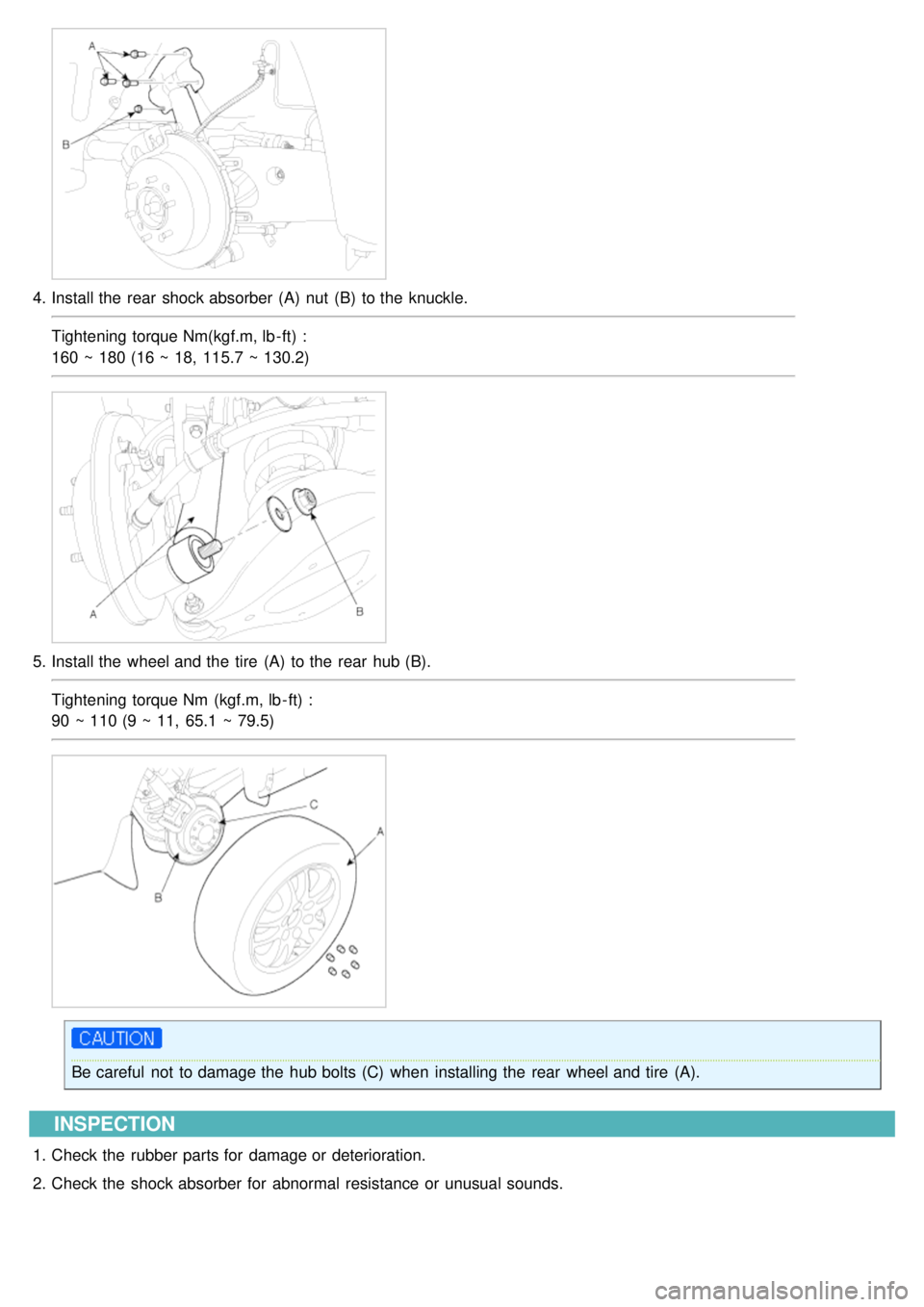
4.Install the rear shock absorber (A) nut (B) to the knuckle.
Tightening torque Nm(kgf.m, lb - ft) :
160 ~ 180 (16 ~ 18, 115.7 ~ 130.2)
5.Install the wheel and the tire (A) to the rear hub (B).
Tightening torque Nm (kgf.m, lb - ft) :
90 ~ 110 (9 ~ 11, 65.1 ~ 79.5)
Be careful not to damage the hub bolts (C) when installing the rear wheel and tire (A).
INSPECTION
1.Check the rubber parts for damage or deterioration.
2. Check the shock absorber for abnormal resistance or unusual sounds.
Page 540 of 1575
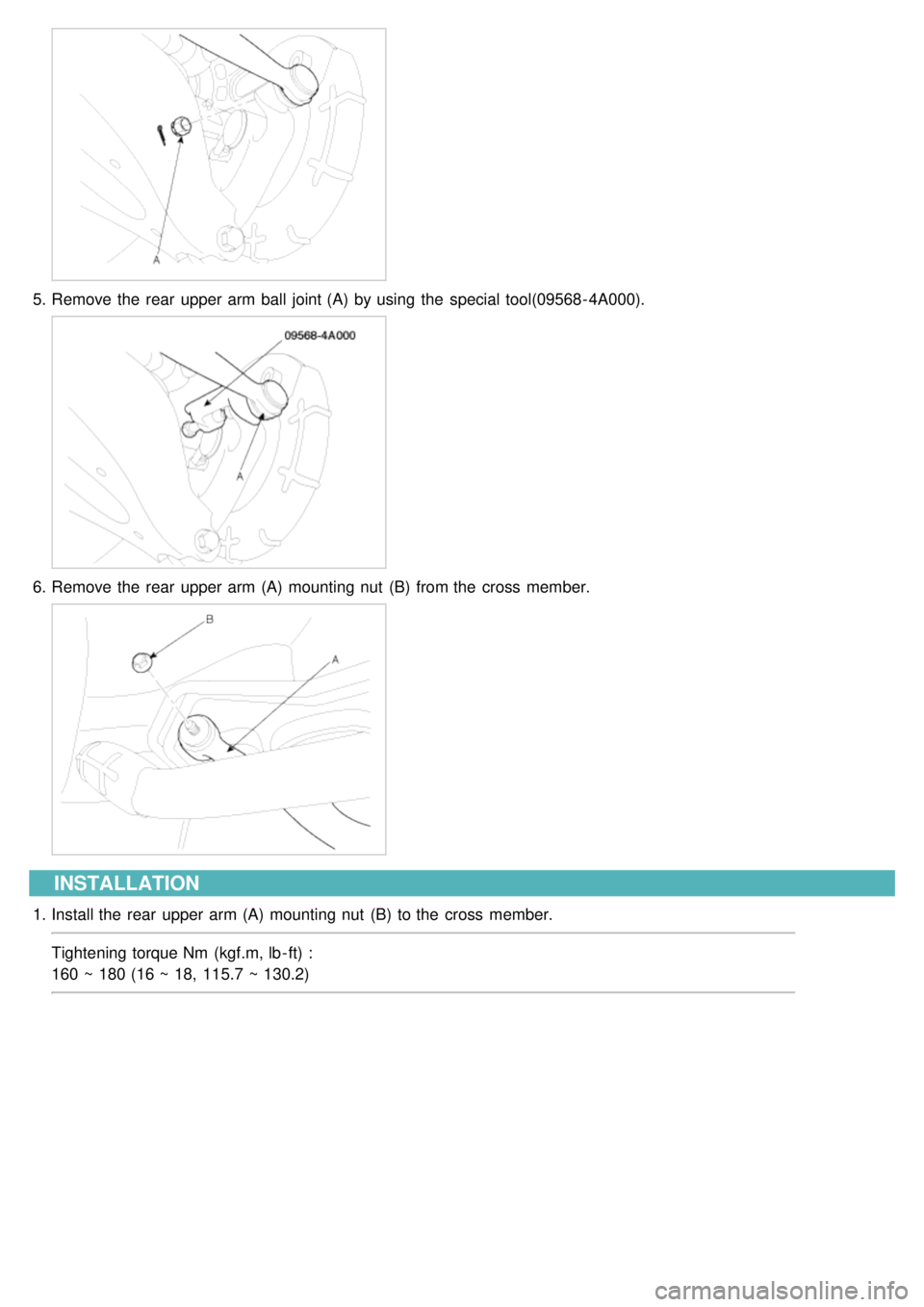
5.Remove the rear upper arm ball joint (A) by using the special tool(09568- 4A000).
6.Remove the rear upper arm (A) mounting nut (B) from the cross member.
INSTALLATION
1.Install the rear upper arm (A) mounting nut (B) to the cross member.
Tightening torque Nm (kgf.m, lb - ft) :
160 ~ 180 (16 ~ 18, 115.7 ~ 130.2)
