headlights Lancia Musa 2007 Owner handbook (in English)
[x] Cancel search | Manufacturer: LANCIA, Model Year: 2007, Model line: Musa, Model: Lancia Musa 2007Pages: 346, PDF Size: 5.15 MB
Page 138 of 346

137
SAFETY
DEVICES
CORRECT
USE OF
THE CAR
WARNING
LIGHTS AND
MESSAGES
IN AN
EMERGENCY
CAR
MAINTENANCE
TECHNICALSPECIFICATIONS
INDEX
DASHBOARD
AND
CONTROLS
To adjust the headlight slant
To adjust the headlight slant operate buttons
andÒlocated on the
dashboard.
The display provides the visual indication of the positions during the
adjustment operation.
Position 0 - one or two people occupying the front seats.
Position 1 - five people.
Position 2 - five people + load in the boot.
Position 3 - driver + maximum permissible load stowed in the boot.
IMPORTANT Check beam aiming every time the load carried
changes.
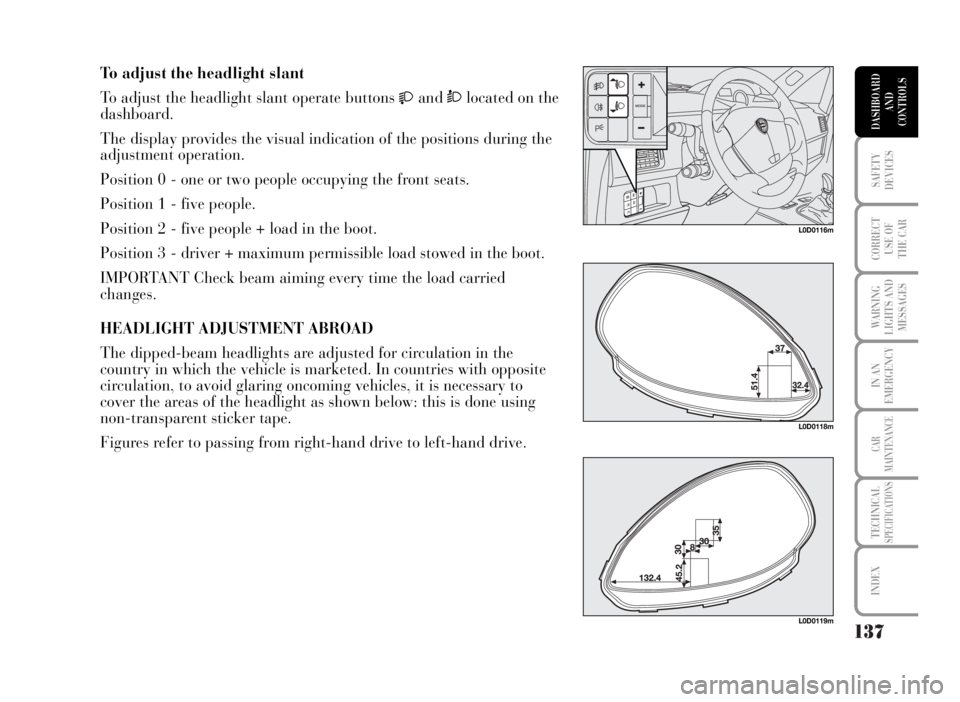
HEADLIGHT ADJUSTMENT ABROAD
The dipped-beam headlights are adjusted for circulation in the
country in which the vehicle is marketed. In countries with opposite
circulation, to avoid glaring oncoming vehicles, it is necessary to
cover the areas of the headlight as shown below: this is done using
non-transparent sticker tape.
Figures refer to passing from right-hand drive to left-hand drive.
L0D0116m
L0D0118m
L0D0119m
Page 202 of 346

Roof rack/ski rack
Remove the roof rack or the ski rack from the roof
as soon as they are no longer used. These
accessories lower air penetration and adversely
affect consumption levels. When needing to carry
particularly voluminous objects, preferably use a
trailer.
Electric devices
Use electric devices only for the amount of time
needed. Rear heated window, additional headlights,
windscreen wipers and heater fan need a
considerable amount of energy, therefore increasing
the requirement of current increases fuel
consumption (up to +25% in the urban cycle).Climate control
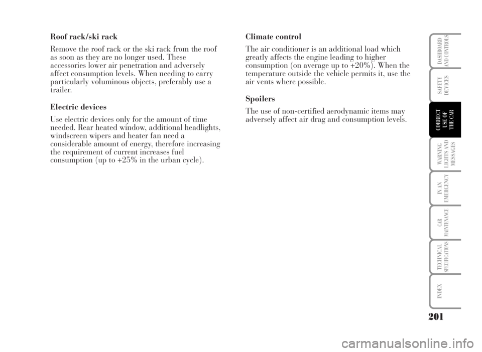
The air conditioner is an additional load which
greatly affects the engine leading to higher
consumption (on average up to +20%). When the
temperature outside the vehicle permits it, use the
air vents where possible.
Spoilers
The use of non-certified aerodynamic items may
adversely affect air drag and consumption levels.
201
WARNING
LIGHTS AND
MESSAGES
IN AN
EMERGENCY
CAR
MAINTENANCE
TECHNICALSPECIFICATIONS
INDEX
DASHBOARD
AND CONTROLS
SAFETY
DEVICES
CORRECT
USE OF
THE CAR
Page 210 of 346

209
IN AN
EMERGENCY
CAR
MAINTENANCE
TECHNICALSPECIFICATIONS
INDEX
DASHBOARD
AND CONTROLS
SAFETY
DEVICES
CORRECT
USE OF
THE CAR
WARNING
LIGHTS AND
MESSAGES
WARNING LIGHTS AND MESSAGES
GEAR NOT AVAILABLE ....................................... 228
MANOEUVRE NOT ENABLED ............................ 229
PRESS BRAKE PEDAL – REPEAT
MANOEUVRE ....................................................... 230
ENGAGE N ........................................................... 231
REAR FOGLIGHTS .............................................. 232
FRONT FOG LIGHTS ........................................... 232
LEFT-HAND DIRECTION INDICATOR ................ 232
RIGHT-HAND DIRECTION INDICATOR .............. 232
SIDELIGHTS AND LOW BEAMS ......................... 233
FOLLOW ME HOME ............................................ 233
MAIN BEAM HEADLIGHTS ................................. 233
CRUISE CONTROL .............................................. 234
POSSIBLE PRESENCE OF ICE ON THE ROAD .. 234
FUEL CUTOFF
SWITCHED ON .................................................... 235
CAR PROTECTION SYSTEM FAILURE -
LANCIA CODE ..................................................... 236
“DUALDRIVE” ELECTRIC POWER
STEERING FAILURE............................................ 237
DIESEL FUEL FILTER SENSOR FAILURE ......... 237
GLOW PLUG WARMING FAILURE...................... 237
ABS SYSTEM FAILURE - SYSTEM
UNAVAILABLE ..................................................... 238
RAIN SENSOR FAILURE ...................................... 238 GENERAL WARNINGS ......................................... 211
LOW BRAKE FLUID............................................. 212
HANDBRAKE ON ................................................. 212
FRONT PASSENGER AIR BAG DEACTIVATED... 213
SEAT BELTS NOT FASTENED............................. 213
LOW BATTERY CHARGE .................................... 214
LOW ENGINE OIL PRESSURE ............................ 214
ENGINE COOLANT FLUID HIGH
TEMPERATURE ................................................... 215
INCOMPLETE DOOR LOCKING .......................... 217
“DUALDRIVE” ELECTRIC POWER
STEERING SYSTEM ............................................ 217
SPEED LIMIT EXCEEDED ................................. 218
FUEL RESERVE ................................................... 218
WATER IN DIESEL FUEL FILTER ...................... 219
GLOW PLUGS ...................................................... 220
ASR - WHEEL ANTISKID SYSTEM ..................... 220
BRAKE PAD WEAR ............................................. 220
LOW TYRE PRESSURE ...................................... 221
GLOW FLAT TYRE ............................................. 222
REDUCE GEARS .................................................. 224
MANUAL MODE NOT AVAILABLE...................... 224
AUTOMATIC MODE NOT AVAILABLE ................ 225
CLUTCH OVERHEATING .................................... 226
PRESS BRAKE PEDAL – DELAYED STARTING ... 227
Page 234 of 346

233
IN AN
EMERGENCY
CAR
MAINTENANCE
TECHNICALSPECIFICATIONS
INDEX
DASHBOARD
AND CONTROLS
SAFETY
DEVICES
CORRECT
USE OF
THE CAR
WARNING
LIGHTS AND
MESSAGES
Warning
light on
dial Message on
multifunction
display
SIDELIGHTS AND LOW BEAMS
The warning light on the dial turns on when sidelights, parking lights
or low beams are turned on. The warning light on the dial will also
turn on when the daylight sensor (where provided) turns the lights
on.
FOLLOW ME HOME
The warning light on the dial comes on (on certain versions, together
with the message on the display) when the “Follow me home” device
is activated (see “Follow me home” in section “Dashboard and
controls”).
MAIN BEAM HEADLIGHTS
The warning light on the dial turns on when the main beams are
turned on.3
1
3
green
green
blue
Page 241 of 346

240
IN AN
EMERGENCY
CAR
MAINTENANCE
TECHNICALSPECIFICATIONS
INDEX
DASHBOARD
AND CONTROLS
SAFETY
DEVICES
CORRECT
USE OF
THE CAR
WARNING
LIGHTS AND
MESSAGES
EXTERNAL LIGHT FAILURE
The warning light on the dial turns on (together with the message on
the display) when one of the following failures is detected: broken
circuit, “missing” or burnt-out bulb, wrong bulb power. Light check
concerns: taillights, brake lights (3rd stop light excluded), rear fog
lights, headlights, direction indicators and number plate lights.
The failure referring to these lights could be: one or more blown
bulbs, a blown protection fuse or a cut-off electric connection.
Symbols
¯/˙(where provided) coming on on the display indicate a
left/right-hand light failure.
W
amber
continued
Warning
light on
dialMessage on
multifunction
display
Page 242 of 346

241
IN AN
EMERGENCY
CAR
MAINTENANCE
TECHNICALSPECIFICATIONS
INDEX
DASHBOARD
AND CONTROLS
SAFETY
DEVICES
CORRECT
USE OF
THE CAR
WARNING
LIGHTS AND
MESSAGES
WEXTERNAL LIGHT FAILURE
The warning light on the dial turns on (together with the message on
the display) when one of the following failures is detected: broken
circuit, “missing” or burnt-out bulb, wrong bulb power. Light check
concerns: taillights, brake lights (3rd stop light excluded), rear fog
lights, headlights, direction indicators and number plate lights.
The failure referring to these lights could be: one or more blown
bulbs, a blown protection fuse or a cut-off electric connection.
Symbols¯/˙coming on on the display indicate a left/right-hand
light failure.amber
continued from previous page
(*)
(*) Or rear
Warning
light on
dial Message on
multifunction
display
Page 270 of 346

269
WARNING
LIGHTS AND
MESSAGES
CAR
MAINTENANCE
TECHNICALSPECIFICATIONS
INDEX
DASHBOARD
AND CONTROLS
SAFETY
DEVICES
CORRECT
USE OF
THE CAR
IN AN
EMERGENCY
IMPORTANT The headlight inner surface may be lightly misted over:
this is not a fault but a natural fact due to low temperature and the
level of air humidity. It will disappear as soon the headlights are
turned on. The presence of drops inside the headlights means water
infiltration, therefore contact Lancia Dealership.
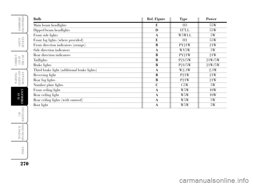
TYPES OF BULBS
Various types of bulbs are fitted to your car:
AGlass bulbs: clipped into position. Pull to remove.
BBayonet type bulbs: press the bulb, turn counterclockwise to
remove this type of bulb from its holder.
CTubular bulbs: free them from their contacts to remove.
D-EHalogen bulbs: to remove the bulb, release the clip holding
the bulb in place.
L0D0178m
Page 271 of 346

270
WARNING
LIGHTS AND
MESSAGES
CAR
MAINTENANCE
TECHNICALSPECIFICATIONS
INDEX
DASHBOARD
AND CONTROLS
SAFETY
DEVICES
CORRECT
USE OF
THE CAR
IN AN
EMERGENCY
Bulb Ref. Figure Type Power
Main beam headlightsEH3 55W
Dipped beam headlights DH7LL 55W
Front side lights AW5WLL 5W
Front fog lights (where provided)EH1 55W
Front direction indicators (orange)BPY21W 21W
Side direction indicators AWY5W 5W
Rear direction indicators BPY21W 21W
Taillights BP21/5W 21W/5W
Brake lightsBP21/5W 21W/5W
Third brake light (additional brake lights) AW2,3W 2,3W
Reversing light BP21W 21W
Rear fog lights BP21W 21W
Number plate lights CC5W 5W
Front ceiling lightAW5W 10W
Rear ceiling lightAW5W 10W
Rear ceiling lights (with sunroof)AW5W 5W
Boot light AW5W 5W
Page 272 of 346

271
WARNING
LIGHTS AND
MESSAGES
CAR
MAINTENANCE
TECHNICALSPECIFICATIONS
INDEX
DASHBOARD
AND CONTROLS
SAFETY
DEVICES
CORRECT
USE OF
THE CAR
IN AN
EMERGENCY
IF AN EXTERIOR LIGHT BURNS OUT
For the type of bulb and power rating, see “When needing to change
a bulb”.
FRONT LIGHT UNITS
The front light units contain the side/taillights, dipped beam, main
beam and direction indicator bulbs.
To replace side/taillight, dipped beam and main beam bulbs:
disconnect the power connector, release retainer B and remove
cover A.
The bulbs are arranged inside the light unit as follows:
C: Direction indicators
D: Main beam headlights
E: Sidelights
F: Dipped beam headlights
Once replacement is over, refit the cover pressing it in the middle
until hearing the locking click. Then, check for proper locking into
place.
L0D0345m
L0D0346m
Page 273 of 346

272
WARNING
LIGHTS AND
MESSAGES
CAR
MAINTENANCE
TECHNICALSPECIFICATIONS
INDEX
DASHBOARD
AND CONTROLS
SAFETY
DEVICES
CORRECT
USE OF
THE CAR
IN AN
EMERGENCY
DIPPED BEAM HEADLIGHTS
To change the bulb, proceed as follows:
❒remove the protective cover releasing the relevant catch;
❒turn the bulb holder A counterclockwise and remove it;
❒release the two tabs B from the catches, remove bulb C and replace
it;
❒refit the bulb holder A into its seat and turn it clockwise.
❒Once replacement is over, refit the cover pressing it in the middle
until hearing the locking click. Then, check for proper locking into
place.
MAIN BEAM HEADLIGHTS
To change the bulb, proceed as follows:
❒remove the protective cover releasing the relevant catch;
❒release the bulb holder catch A;
❒disconnect the electric connector B;
❒remove the bulb C and replace it;
❒fit the new bulb, making the tabs of the metallic part coincide with
the grooves on the reflector, reconnect the electrical connector B
then hook the bulb holder catch A;
❒Once replacement is over, refit the cover pressing it in the middle
until hearing the locking click. Then, check for proper locking into
place.
L0D0348m
L0D0350m