climate control Lancia Musa 2007 Owner handbook (in English)
[x] Cancel search | Manufacturer: LANCIA, Model Year: 2007, Model line: Musa, Model: Lancia Musa 2007Pages: 346, PDF Size: 5.15 MB
Page 8 of 346

7
SAFETY
DEVICES
CORRECT
USE OF
THE CAR
WARNING
LIGHTS AND
MESSAGES
IN AN
EMERGENCY
CAR
MAINTENANCE
TECHNICALSPECIFICATIONS
INDEX
DASHBOARD
AND
CONTROLSSYMBOLS ............................................................ 8
THE LANCIA CODE SYSTEM .............................. 8
KEY KIT AND DOOR LOCKING ......................... 10
IGNITION SWITCH .............................................. 20
DASHBOARD ........................................................ 23
INSTRUMENT PANEL ......................................... 26
INSTRUMENTS .................................................... 27
MULTIFUNCTION DISPLAY
(On two-line mode panel) ..................................... 29
MULTIFUNCTION DISPLAY
(On three-line comfort panel) ............................... 37
STEERING WHEEL ADJUSTMENT .................... 69
SEAT ADJUSTMENT ........................................... 70
HEAD RESTRAINTS ............................................ 77
REARVIEW MIRRORS .......................................... 79
HEATING/CLIMATE CONTROL SYSTEM .......... 81
MANUAL CLIMATE CONTROL SYSTEM ........... 83
AUTOMATIC TWO-ZONE CLIMATE
CONTROL SYSTEM ............................................ 88
EXTERNAL LIGHTS ............................................ 99
WINDOW WASHING ............................................ 104
CRUISE CONTROL ............................................. 109
CEILING LIGHTS ................................................ 112
LIGHT CONTROL BUTTONS .............................. 115INERTIAL FUEL CUT-OFF
SWITCH ................................................................ 117
INTERIOR FITTINGS .......................................... 118
SMOKERS’ KIT ..................................................... 123
SUN VISORS ......................................................... 123
SUNROOF ............................................................. 124
POWER WINDOWS ............................................. 126
REAR WINDOW WINDERS .................................. 129
BOOT .................................................................... 129
BONNET ............................................................... 134
ROOF/SKI RACKS ................................................ 136
HEADLIGHTS ...................................................... 136
ABS SYSTEM ....................................................... 138
ESP SYSTEM ....................................................... 140
ASR SYSTEM ........................................................ 142
EOBD SYSTEM .................................................... 144
TYRE PRESSURE MONITORING
SYSTEM - T.P.M.S................................................. 145
SOUND SYSTEM .................................................. 147
ACCESSORIES PURCHASED BY THE OWNER .. 149
“DUALDRIVE” ELECTRIC POWER
STEERING SYSTEM ............................................ 150
PARKING SENSORS ............................................ 152
AT THE FILLING STATION ................................ 154
PROTECTING THE ENVIRONMENT .................. 156
DASHBOARD AND CONTROLS
Page 24 of 346

23
SAFETY
DEVICES
CORRECT
USE OF
THE CAR
WARNING
LIGHTS AND
MESSAGES
IN AN
EMERGENCY
CAR
MAINTENANCE
TECHNICALSPECIFICATIONS
INDEX
DASHBOARD
AND
CONTROLS
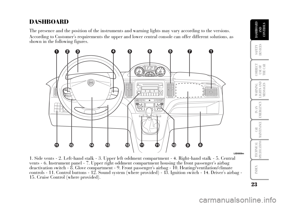
L0D0009m
1. Side vents - 2. Left-hand stalk - 3. Upper left oddment compartment - 4. Right-hand stalk - 5. Central
vents - 6. Instrument panel - 7. Upper right oddment compartment housing the front passenger’s airbag
deactivation switch - 8. Glove compartment - 9. Front passenger’s airbag - 10. Heating/ventilation/climate
controls - 11. Control buttons - 12. Sound system (where provided) - 13. Ignition switch - 14. Driver’s airbag -
15. Cruise Control (where provided).
DASHBOARD
The presence and the position of the instruments and warning lights may vary according to the versions.
According to Customer’s requirements the upper and lower central console can offer different solutions, as
shown in the following figures.
Page 26 of 346

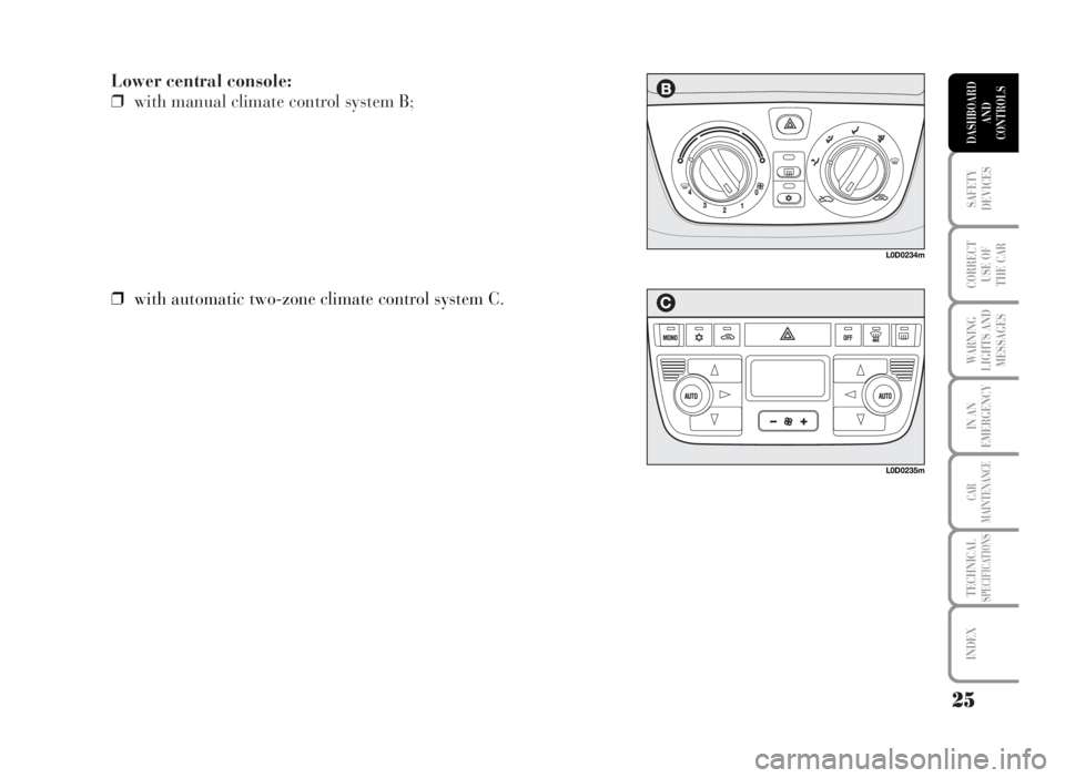
Lower central console:
❒with manual climate control system B;
25
SAFETY
DEVICES
CORRECT
USE OF
THE CAR
WARNING
LIGHTS AND
MESSAGES
IN AN
EMERGENCY
CAR
MAINTENANCE
TECHNICALSPECIFICATIONS
INDEX
DASHBOARD
AND
CONTROLS
❒with automatic two-zone climate control system C.
L0D0234m
L0D0235m
Page 28 of 346

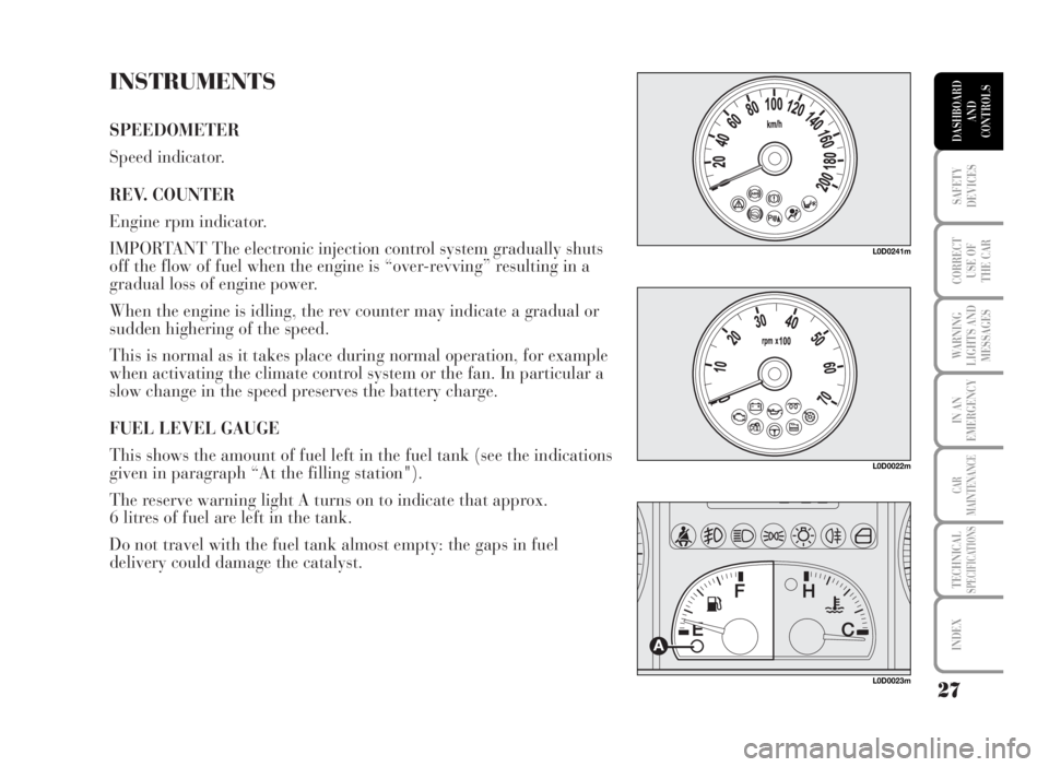
INSTRUMENTS
SPEEDOMETER
Speed indicator.
REV. COUNTER
Engine rpm indicator.
IMPORTANT The electronic injection control system gradually shuts
off the flow of fuel when the engine is “over-revving” resulting in a
gradual loss of engine power.
When the engine is idling, the rev counter may indicate a gradual or
sudden highering of the speed.
This is normal as it takes place during normal operation, for example
when activating the climate control system or the fan. In particular a
slow change in the speed preserves the battery charge.
FUEL LEVEL GAUGE
This shows the amount of fuel left in the fuel tank (see the indications
given in paragraph “At the filling station").
The reserve warning light A turns on to indicate that approx.
6 litres of fuel are left in the tank.
Do not travel with the fuel tank almost empty: the gaps in fuel
delivery could damage the catalyst.
27
SAFETY
DEVICES
CORRECT
USE OF
THE CAR
WARNING
LIGHTS AND
MESSAGES
IN AN
EMERGENCY
CAR
MAINTENANCE
TECHNICALSPECIFICATIONS
INDEX
DASHBOARD
AND
CONTROLS
L0D0022m
L0D0023m
L0D0241m
Page 38 of 346

MULTIFUNCTION DISPLAY
(On three-line comfort panel)
The “Multifunction display” shows all the useful information
necessary when driving, more particularly:
INFORMATION ON STANDARD SCREEN
❒Date A.
❒Mileage recorder B.
❒Clock C.
❒External temperature D.
When the ignition key is removed only the time is displayed; when
opening one of the front doors the display comes on showing the
odometer indication.
INFORMATION ABOUT CAR CONDITIONS (at event)
❒Scheduled maintenance programme intervals.
❒ Trip computer information.
❒To adjust the intensity of the instrument dimmer/ menus/
instrument panel, sound system and automatic two-zone climate
control system display.
❒Display of failure/warning messages/function activation.
❒Display of the CITY mode (if selected).
❒Headlight aiming position display (with dipped beam headlights
on) E.
❒Symbol for possible ice on road.
37
SAFETY
DEVICES
CORRECT
USE OF
THE CAR
WARNING
LIGHTS AND
MESSAGES
IN AN
EMERGENCY
CAR
MAINTENANCE
TECHNICALSPECIFICATIONS
INDEX
DASHBOARD
AND
CONTROLS
FOH9000m
Page 39 of 346

CONTROL BUTTONS
To use the information the “Multifunction display” is able to give you
should firstly familiarise with the control buttons using them as
described below.
Before doing anything you are advised to read this section thoroughly.
+ and – buttons
To scroll the menu and the related options upwards/downwards, to
increase/decrease/set the value displayed and, with side/taillights on,
to adjust the intensity of the instrument dimmer/ menus/ instrument
panel, sound system and automatic two-zone climate control system
display (if pressed with “Set-up menu on”).
MODE button
Press for less than 2 seconds (pulse) indicated with
bin the
following diagrams, to confirm the option required and/or move to
the main screen (same option) or access the Menu.
Press for more than 2 seconds indicated with
cin the following
diagrams, to exit the set-up menu during setting.
TRIP button
Press for less than 1 seconds (pulse) indicated with
hin the
following diagrams, to scroll the Trip computer screens.
Press for more than 2 seconds indicated with
iin the following
diagrams, to reset the Trip computer and start a new mission.
38
SAFETY
DEVICES
CORRECT
USE OF
THE CAR
WARNING
LIGHTS AND
MESSAGES
IN AN
EMERGENCY
CAR
MAINTENANCE
TECHNICALSPECIFICATIONS
INDEX
DASHBOARD
AND
CONTROLS
L0D0025m
L0D0026m
Page 68 of 346

67
SAFETY
DEVICES
CORRECT
USE OF
THE CAR
WARNING
LIGHTS AND
MESSAGES
IN AN
EMERGENCY
CAR
MAINTENANCE
TECHNICALSPECIFICATIONS
INDEX
DASHBOARD
AND
CONTROLS
INSTRUMENT PANEL, DISPLAY AND BUTTON LIGHTING ADJUSTMENT
(LIGHT RHEOSTAT)
With this function it is possible to adjust the lighting (dimming/brightening) of the instrument cluster and two-
zone climate control display (where provided).
To adjust proceed as follows:
See “Initial check”
and “Access to
menu screen”
– +– +
Automatic return to standard screen
after few seconds or by
pressing button
Q
Previously
displayed
screen, e.g.:Use buttons +/– to carry out required
light adjustment.
L0D0040m
Q= Press “MODE” button for less than two seconds
R= Press “MODE” button for over two seconds
Page 82 of 346

81
SAFETY
DEVICES
CORRECT
USE OF
THE CAR
WARNING
LIGHTS AND
MESSAGES
IN AN
EMERGENCY
CAR
MAINTENANCE
TECHNICALSPECIFICATIONS
INDEX
DASHBOARD
AND
CONTROLS
HEATING/CLIMATE CONTROL SYSTEM
1 Fixed vents for defrosting/demisting side windows - 2 Side adjustable outlets - 3 Fixed vents for
defrosting/demisting windscreen - 4 Centre adjustable outlets - 5 Lower vents - 6 Lower vents for rear
passengers.
L0D0060m
Page 84 of 346

83
SAFETY
DEVICES
CORRECT
USE OF
THE CAR
WARNING
LIGHTS AND
MESSAGES
IN AN
EMERGENCY
CAR
MAINTENANCE
TECHNICALSPECIFICATIONS
INDEX
DASHBOARD
AND
CONTROLS
MANUAL CLIMATE CONTROL SYSTEM (where provided)
AIR DISTRIBUTION
Using knob E it is possible to choose
manually 5 of the possible air distributions
to the passenger compartment:
«air flow from central vents and side
outlets 2 and 4;
Δair flow from centre and side vents 2 and
4 and downwards 5 and 6 (bilevel
function);
≈air flow downwards 5 and 6;
ƒair flow downwards 5 and 6 and also to
the windscreen 3;
-to demist and defrost windscreen 3 and
front side windows 1.
CONTROLS
A fan activation and speed control knob
B air temperature knob (mixing hot and cold air)
C heated rear window on/off button
D climate control compressor on/off button;
E air distribution selection knob
F air recirculation on/off button.
L0D0064m
Page 87 of 346

86
SAFETY
DEVICES
CORRECT
USE OF
THE CAR
WARNING
LIGHTS AND
MESSAGES
IN AN
EMERGENCY
CAR
MAINTENANCE
TECHNICALSPECIFICATIONS
INDEX
DASHBOARD
AND
CONTROLS
QUICK WINDSCREEN AND FRONT SIDE
WINDOW DEMISTING/DEFROSTING
Proceed as follows:
❒turn knob B to the red sector;
❒turn knob A to 4 -;
❒turn knob E to -;
❒set knob F to Uto turn air recirculation off.
After demisting/defrosting, operate the controls to
restore the required comfort.
Preventive demisting procedure
In the event of considerable outside moisture and/or
rain and/or considerable differences in temperature
inside and outside the passenger compartment,
perform the following preventive demisting
procedure:
❒set knob F to Uto turn air recirculation off;
❒turn knob B to the red sector;
❒turn knob A to 2;
❒turn knob E to to -or to ƒif the windows do
not mist up.
IMPORTANT Climate control is very useful to speed
up window demisting: therefore, perform demisting
procedure as described previously and then switch
the system on pressing button D.REAR WINDOW AND ELECTRIC DOOR
MIRROR DEMISTING/DEFROSTING
(where provided)
Press button C to turn this function on. When this
function is on, the button led turns on.
This function is timed and switches off
automatically after the preset time. To cut out this
function press again button C.
IMPORTANT Do not apply stickers on the inside of
the rear window over the heating filaments to avoid
damage that might cause it to stop working
properly.