technical specifications Lancia Musa 2009 Owner handbook (in English)
[x] Cancel search | Manufacturer: LANCIA, Model Year: 2009, Model line: Musa, Model: Lancia Musa 2009Pages: 218, PDF Size: 3.7 MB
Page 18 of 218
17
SAFETY
DEVICES
STARTING
AND
DRIVING
WARNING
LIGHTS AND
MESSAGES
IN AN
EMERGENCY
MAINTENANCE
AND CARE
TECHNICALSPECIFICATIONS
INDEX
DASHBOARD
AND CONTROLS
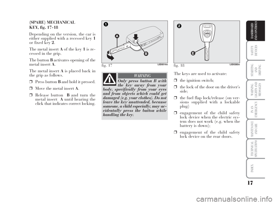
(SPARE) MECHANICAL
KEY, fig. 17-18
Depending on the version, the car is
either supplied with a recessed key 1
or fixed key 2.
The metal insert Aof the key 1is re-
cessed in the grip.
The button Bactivates opening of the
metal insert A.
The metal insert Ais placed back in
the grip as follows.
❒Press button Band hold it pressed.
❒Move the metal insert A.
❒Release buttonBand turn the
metal insertAuntil hearing the
click that indicates correct locking.The keys are used to activate:
❒the ignition switch;
❒the lock of the door on the driver’s
side;
❒the fuel flap lock/release (on ver-
sions supplied with a lockable
plug)
❒engagement of the child safety
lock device when the electric sys-
tem does not work (e.g. when the
battery is down);
❒engagement of the child safety
lock device on the rear doors.
fig. 17L0D0014mfig. 18L0D0380m
Only press button B with
the key away from your
body, specifically from your eyes
and from objects which could get
damaged (e.g. your clothes). Do not
leave the key unattended, because
someone, a child especially, may ac-
cidentally press the button while
handling the key.
WARNING
007-037 MUSA 1ed GB 10-07-2008 9:36 Pagina 17
Page 19 of 218
18
SAFETY
DEVICES
STARTING
AND
DRIVING
WARNING
LIGHTS AND
MESSAGES
IN AN
EMERGENCY
MAINTENANCE
AND CARE
TECHNICALSPECIFICATIONS
INDEX
DASHBOARD
AND CONTROLS
Type of key
Spare
mechanical
key
Main keywith remote control
Direction indicators flashing
(only when key
has remote control)
Deterrence led
Pressing button Ëactivates opening of the fuel flap.
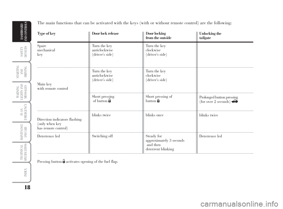
The main functions that can be activated with the keys (with or without remote control) are the following:
Door locking
from the outside
Turn the key
clockwise
(driver’s side)
Turn the key
clockwise
(driver’s side)
Short pressing of
buttonÁ
blinks once
Steady for
approximately 3 seconds
and then
deterrent blinkingUnlocking the
tailgate
Prolonged button pressing
(for over 2 seconds) R
blinks twice
Deterrence led Door lock release
Turn the key
anticlockwise
(driver’s side)
Turn the key
anticlockwise
(driver’s side)
Short pressing
of button Ë
blinks twice
Switching off
007-037 MUSA 1ed GB 10-07-2008 9:36 Pagina 18
Page 20 of 218
19
SAFETY
DEVICES
STARTING
AND
DRIVING
WARNING
LIGHTS AND
MESSAGES
IN AN
EMERGENCY
MAINTENANCE
AND CARE
TECHNICALSPECIFICATIONS
INDEX
DASHBOARD
AND CONTROLS
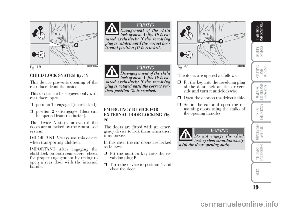
CHILD LOCK SYSTEM fig. 19
This device prevents opening of the
rear doors from the inside.
This device can be engaged only with
rear doors open.
❒position1- engaged (door locked);
❒position2- disengaged (door can
be opened from the inside).
The device Astays on even if the
doors are unlocked by the centralised
system.
IMPORTANT Always use this device
when transporting children.
IMPORTANT After engaging the
child lock on both rear doors, check
for proper engagement by trying to
open a rear door with the internal
handle.The doors are opened as follows.
❒Fit the key into the revolving plug
of the door lock on the driver’s
side and turn it anticlockwise.
❒Open the door on the driver’s side.
❒Sit in the car and open the re-
maining doors using the stalks of
the opening handles.
fig. 19L0D0101m
Engagement of the child
lock system A-fig. 19 is en-
sured exclusively if the revolving
plug is rotated until the correct hor-
izontal position (1) is reached.
WARNING
Disengagement of the child
lock system A-fig. 19 is en-
sured exclusively if the revolving
plug is rotated until the correct ver-
tical position (2) is reached.
WARNING
EMERGENCY DEVICE FOR
EXTERNAL DOOR LOCKING fig.
20
The doors are fitted with an emer-
gency device to lock them when there
is no power.
In this case, the car doors are locked
as follows.
❒Fit the ignition key into the re-
volving plug B.
❒Turn the device to position 1and
close the door.
fig. 20L0D0247
Do not engage the child
lock system simultaneously
with the door opening stalk.
WARNING
007-037 MUSA 1ed GB 10-07-2008 9:36 Pagina 19
Page 21 of 218
20
SAFETY
DEVICES
STARTING
AND
DRIVING
WARNING
LIGHTS AND
MESSAGES
IN AN
EMERGENCY
MAINTENANCE
AND CARE
TECHNICALSPECIFICATIONS
INDEX
DASHBOARD
AND CONTROLS
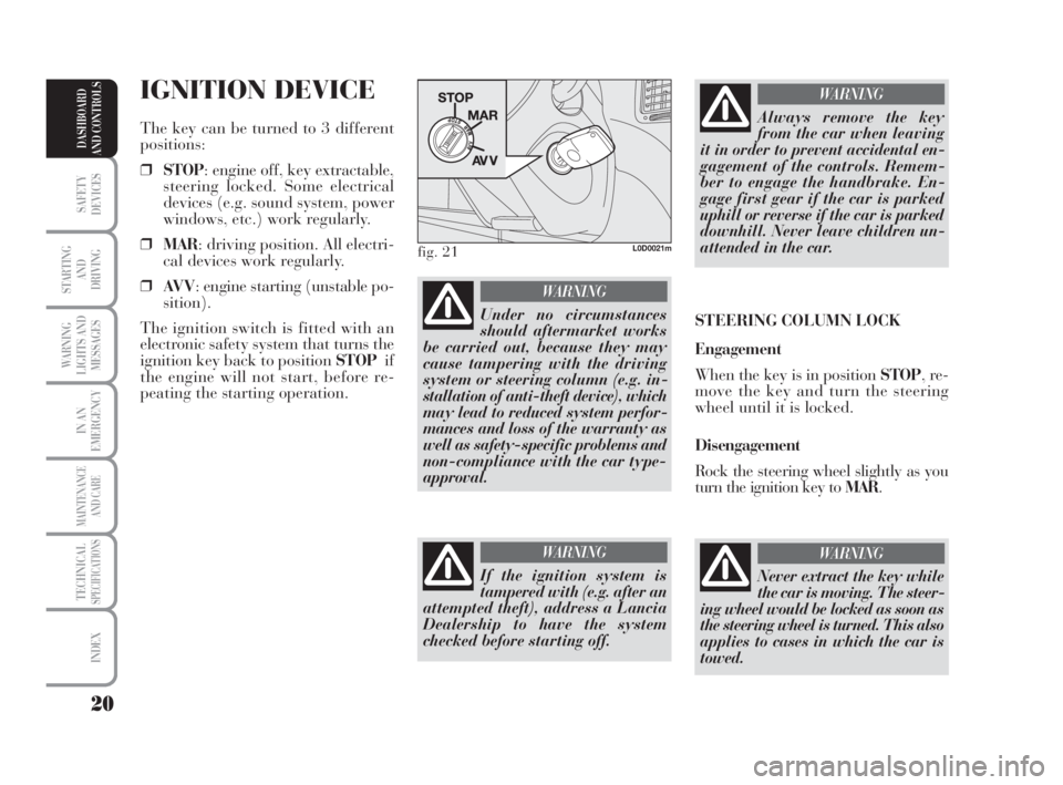
IGNITION DEVICE
The key can be turned to 3 different
positions:
❒STOP: engine off, key extractable,
steering locked. Some electrical
devices (e.g. sound system, power
windows, etc.) work regularly.
❒MAR: driving position. All electri-
cal devices work regularly.
❒AV V: engine starting (unstable po-
sition).
The ignition switch is fitted with an
electronic safety system that turns the
ignition key back to position STOPif
the engine will not start, before re-
peating the starting operation.
Under no circumstances
should aftermarket works
be carried out, because they may
cause tampering with the driving
system or steering column (e.g. in-
stallation of anti-theft device), which
may lead to reduced system perfor-
mances and loss of the warranty as
well as safety-specific problems and
non-compliance with the car type-
approval.
WARNING
fig. 21L0D0021m
If the ignition system is
tampered with (e.g. after an
attempted theft), address a Lancia
Dealership to have the system
checked before starting off.
WARNING
Always remove the key
from the car when leaving
it in order to prevent accidental en-
gagement of the controls. Remem-
ber to engage the handbrake. En-
gage first gear if the car is parked
uphill or reverse if the car is parked
downhill. Never leave children un-
attended in the car.
WARNING
STEERING COLUMN LOCK
Engagement
When the key is in position STOP, re-
move the key and turn the steering
wheel until it is locked.
Disengagement
Rock the steering wheel slightly as you
turn the ignition key to MAR.
Never extract the key while
the car is moving. The steer-
ing wheel would be locked as soon as
the steering wheel is turned. This also
applies to cases in which the car is
towed.
WARNING
007-037 MUSA 1ed GB 10-07-2008 9:36 Pagina 20
Page 22 of 218
21
SAFETY
DEVICES
STARTING
AND
DRIVING
WARNING
LIGHTS AND
MESSAGES
IN AN
EMERGENCY
MAINTENANCE
AND CARE
TECHNICALSPECIFICATIONS
INDEX
DASHBOARD
AND CONTROLS
INSTRUMENTS
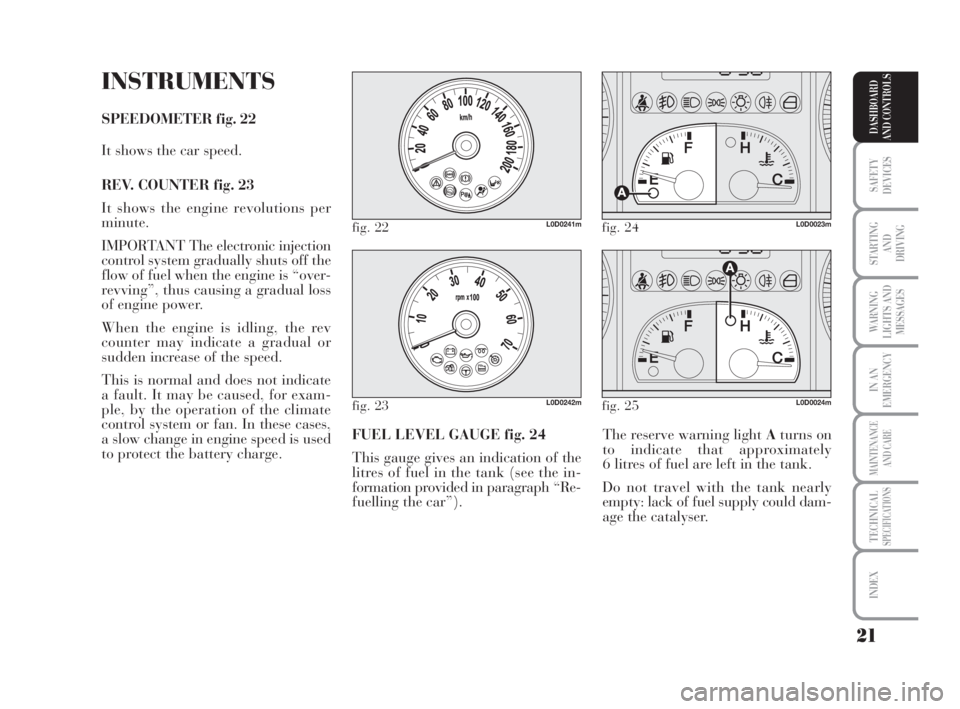
SPEEDOMETER fig. 22
It shows the car speed.
REV. COUNTER fig. 23
It shows the engine revolutions per
minute.
IMPORTANT The electronic injection
control system gradually shuts off the
flow of fuel when the engine is “over-
revving”, thus causing a gradual loss
of engine power.
When the engine is idling, the rev
counter may indicate a gradual or
sudden increase of the speed.
This is normal and does not indicate
a fault. It may be caused, for exam-
ple, by the operation of the climate
control system or fan. In these cases,
a slow change in engine speed is used
to protect the battery charge.The reserve warning light Aturns on
to indicate that approximately
6 litres of fuel are left in the tank.
Do not travel with the tank nearly
empty: lack of fuel supply could dam-
age the catalyser. FUEL LEVEL GAUGE fig. 24
This gauge gives an indication of the
litres of fuel in the tank (see the in-
formation provided in paragraph “Re-
fuelling the car”).
fig. 22L0D0241mfig. 24L0D0023m
fig. 23L0D0242mfig. 25L0D0024m
007-037 MUSA 1ed GB 10-07-2008 9:36 Pagina 21
Page 23 of 218
22
SAFETY
DEVICES
STARTING
AND
DRIVING
WARNING
LIGHTS AND
MESSAGES
IN AN
EMERGENCY
MAINTENANCE
AND CARE
TECHNICALSPECIFICATIONS
INDEX
DASHBOARD
AND CONTROLS
MULTIFUNCTIONAL
DISPLAY
(on two-line modal
panel)
The car can be equipped with a multi-
function display that shows useful in-
formation for car driving according to
the settings made. ENGINE COOLANT
TEMPERATURE GAUGE fig. 25
Warning light Aturns on to indicate
that the temperature of the engine
coolant has remarkably increased. In
this case, stop the engine and go to a
Lancia Dealership. This shows the tem-
perature of the engine coolant fluid and
starts working when the fluid temper-
ature exceeds approx. 50°C. In regular
operating conditions the needle moves
to the different positions allowed inside
the gauge according to the car operat-
ing conditions and management of the
engine cooling system.
IMPORTANT If the needle gets posi-
tioned at the beginning of the scale
(temperature low) and the warning
lightAis on, a failure has occurred in
the system. If this is the case, go to a
Lancia Dealership to have the system
checked.
If the needle indicating the
engine coolant temperature
reaches the red area, stop the
engine immediately and con-
tact a Lancia Dealership.
fig. 26L0D0027m
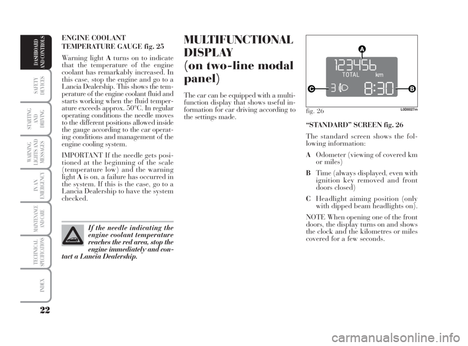
“STANDARD” SCREEN fig. 26
The standard screen shows the fol-
lowing information:
AOdometer (viewing of covered km
or miles)
BTime (always displayed, even with
ignition key removed and front
doors closed)
CHeadlight aiming position (only
with dipped beam headlights on).
NOTE When opening one of the front
doors, the display turns on and shows
the clock and the kilometres or miles
covered for a few seconds.
007-037 MUSA 1ed GB 10-07-2008 9:36 Pagina 22
Page 24 of 218
23
SAFETY
DEVICES
STARTING
AND
DRIVING
WARNING
LIGHTS AND
MESSAGES
IN AN
EMERGENCY
MAINTENANCE
AND CARE
TECHNICALSPECIFICATIONS
INDEX
DASHBOARD
AND CONTROLS
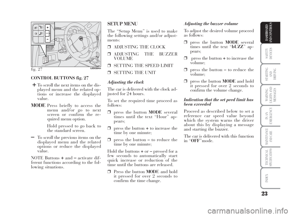
CONTROL BUTTONS fig. 27
+To scroll the next items on the dis-
played menu and the related op-
tions or increase the displayed
value.
MODEPress briefly to access the
menu and/or go to next
screen or confirm the re-
quired menu option.
Hold pressed to go back to
the standard screen.
–To scroll the previous items on the
displayed menu and the related
options or reduce the displayed
value.
NOTE Buttons
+and–activate dif-
ferent functions according to the fol-
lowing situations.Adjusting the buzzer volume
To adjust the desired volume proceed
as follows:
❒press the button MODEseveral
times until the text “bUZZ” ap-
pears;
❒press the button +to increase the
volume;
❒press the button –to reduce the
volume;
❒press the button MODEand hold
it pressed for over 2 seconds to
confirm the volume change.
Indication that the set peed limit has
been exceeded
Proceed as described below to set a
reference car speed value beyond
which the system warns the driver
about this by displaying a message
and starting the buzzer.
The car is delivered with this function
in “OFF”mode.
SETUP MENU
The “Setup Menu” is used to make
the following settings and/or adjust-
ments:
❒ADJUSTING THE CLOCK
❒ADJUSTING THE BUZZER
VOLUME
❒SETTING THE SPEED LIMIT
❒SETTING THE UNIT
Adjusting the clock
The car is delivered with the clock ad-
justed for 24 hours.
To set the required time proceed as
follows:
❒press the button MODEseveral
times until the text “Hour” ap-
pears;
❒press the button +to increase the
time by one minute;
❒press the button –to reduce the
time by one minute;
Hold the buttons +or–pressed for a
few seconds to automatically start
quick increase or reduction of the
time until the buttons are released.
❒Press the button MODE and hold
it pressed for over 2 seconds to
confirm the time change.
fig. 27L0D0384m
007-037 MUSA 1ed GB 10-07-2008 9:36 Pagina 23
Page 25 of 218
24
SAFETY
DEVICES
STARTING
AND
DRIVING
WARNING
LIGHTS AND
MESSAGES
IN AN
EMERGENCY
MAINTENANCE
AND CARE
TECHNICALSPECIFICATIONS
INDEX
DASHBOARD
AND CONTROLS
Setting the unit
To set the required unit (kilometres or
miles) proceed as follows:
❒press the button MODEseveral
times until the text “Unit” ap-
pears;
❒press the button +or–to change
the unit;
❒press the button MODEand hold
it pressed for over 2 seconds to
confirm the unit setting.
V iewing of the
fuel cut-off inertial switch
tripping
The screen automatically appears
whenever the fuel cut-off inertial
switch trips after a significant colli-
sion.
This switch stops fuel supply.
See the information provided in the
dedicated chapter “Fuel cut-off iner-
tial switch”. Set this function as follows:
❒press the button MODEseveral
times until the text “SPEED” ap-
pears;
❒press the button +to increase the
speed value (max. limit being 250
Km/h);
❒press the button –to reduce the
speed value (min. limit being 30
Km/h below which the system
goes back to “OFF” mode);
❒press the button MODEand hold
it pressed for over 2 seconds to
confirm the speed setting.
If, after the message
“FPSon” appears, you
smell fuel or see leaks from the fuel
supply system, do not reset the
switch to avoid the risk of starting a
fire.
WARNING
007-037 MUSA 1ed GB 10-07-2008 9:36 Pagina 24
Page 26 of 218
25
SAFETY
DEVICES
STARTING
AND
DRIVING
WARNING
LIGHTS AND
MESSAGES
IN AN
EMERGENCY
MAINTENANCE
AND CARE
TECHNICALSPECIFICATIONS
INDEX
DASHBOARD
AND CONTROLS
fig. 29L0D09000m
MULTIFUNCTIONAL
DISPLAY
(on three-line
comfort panel)
The car can be equipped with a mul-
tifunction display that shows useful
information for car driving according
to the settings made.
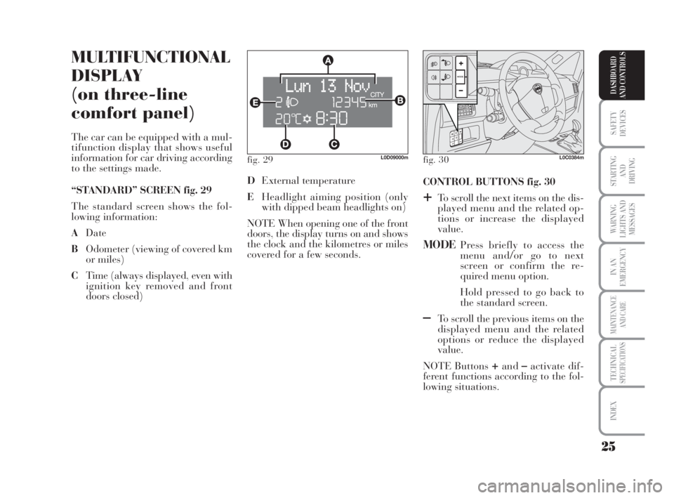
“STANDARD” SCREEN fig. 29
The standard screen shows the fol-
lowing information:
ADate
BOdometer (viewing of covered km
or miles)
CTime (always displayed, even with
ignition key removed and front
doors closed)CONTROL BUTTONS fig. 30
+To scroll the next items on the dis-
played menu and the related op-
tions or increase the displayed
value.
MODEPress briefly to access the
menu and/or go to next
screen or confirm the re-
quired menu option.
Hold pressed to go back to
the standard screen.
–To scroll the previous items on the
displayed menu and the related
options or reduce the displayed
value.
NOTE Buttons
+and–activate dif-
ferent functions according to the fol-
lowing situations. DExternal temperature
EHeadlight aiming position (only
with dipped beam headlights on)
NOTE When opening one of the front
doors, the display turns on and shows
the clock and the kilometres or miles
covered for a few seconds.
fig. 30L0C0384m
007-037 MUSA 1ed GB 10-07-2008 9:36 Pagina 25
Page 27 of 218
26
SAFETY
DEVICES
STARTING
AND
DRIVING
WARNING
LIGHTS AND
MESSAGES
IN AN
EMERGENCY
MAINTENANCE
AND CARE
TECHNICALSPECIFICATIONS
INDEX
DASHBOARD
AND CONTROLS
Adjustment of
headlight aiming device (only with
dipped beam headlights on)
- when the standard screen is enabled,
the headlight aiming device can be
regulated (refer to paragraph “Head-
lights” in this section).
Setup menu
- to scroll the previous and next items
in the menu;
- to increase or decrease values dur-
ing setting operations.
SETUP MENU fig. 31
The menu comprises a series of func-
tions arranged in a cycle which can be
selected through buttons
+and–to
access the different “select” opera-
tions and settings (setup) described in
the following paragraphs.
The setup menu is activated by press-
ing briefly button MODE.
Intermittent pressing of buttons
+and–enables scrolling of the setup menu
options.
Handling modes are different accord-
ing to the characteristic of the option
selected.Selecting the “Set Date”
and “Set time”
– Briefly press button MODEto select
the first value to be changed (e.g.
hours /minutes or year / month /
day).
– Press buttons
+and–(by single
pressing) to select the new setting.
– Briefly press button MODEto store
the new setting and at the same time
go to the next setup menu option. If
the processed option is the last one,
the system brings you back to the pre-
viously selected option of the main
menu.
Prolonged pressing of the
button MODE enables:
– exiting the setup menu page and
saving of the changes already stored
by the driver (and confirmed by
briefly pressing the button MODE).
The setup menu page is timed. Only
the changes saved by the user by
briefly pressing MODEare saved
when the menu is automatically
closed. NOTE If the Connect Nav+ system is
installed, only the following functions
can be adjusted/set from the Instru-
ment Panel: “Brightness”, “Speed
Beep”, Light Sensors” (where pro-
vided), “Seat belt Buzzer” and “Pas-
senger’s Airbag”. The other functions
are displayed on the Connect Nav+
system which is used to adjust/set
them.
Selecting a menu option
– Briefly press button MODEto select
the menu option that needs to be
changed.
– Press buttons
+and–(by single
pressing) to select the new setting.
– Briefly press button MODEto store
the new setting and at the same time
go back to the previously selected
menu option.
007-037 MUSA 1ed GB 10-07-2008 9:36 Pagina 26