technical specifications Lancia Musa 2009 Owner handbook (in English)
[x] Cancel search | Manufacturer: LANCIA, Model Year: 2009, Model line: Musa, Model: Lancia Musa 2009Pages: 218, PDF Size: 3.7 MB
Page 38 of 218
37
SAFETY
DEVICES
STARTING
AND
DRIVING
WARNING
LIGHTS AND
MESSAGES
IN AN
EMERGENCY
MAINTENANCE
AND CARE
TECHNICALSPECIFICATIONS
INDEX
DASHBOARD
AND CONTROLS
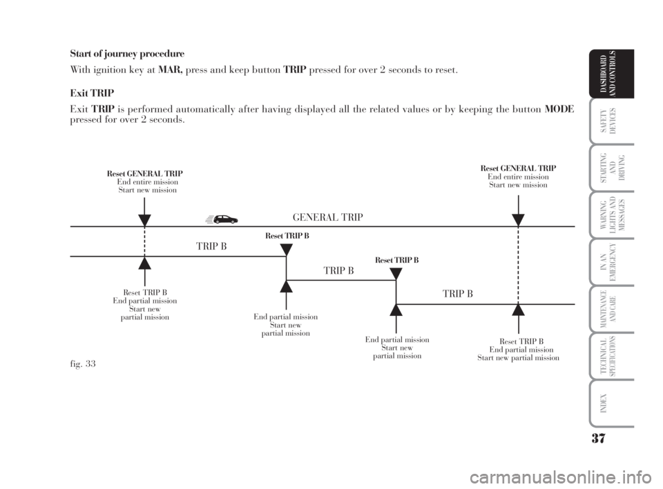
Start of journey procedure
With ignition key at MAR,press and keep button TRIPpressed for over 2 seconds to reset.
Exit TRIP
ExitT RIPis performed automatically after having displayed all the related values or by keeping the button MODE
pressed for over 2 seconds.
Reset TRIP B
End partial mission
Start new
partial missionEnd partial mission
Start new
partial mission
Reset TRIP B
End partial mission
Start new partial mission Reset GENERAL TRIP
End entire mission
Start new missionReset GENERAL TRIP
End entire mission
Start new mission
End partial mission
Start new
partial mission Reset TRIP B
Reset TRIP B
TRIP B
TRIP B
TRIP B GENERAL TRIP
˙
˙
˙
˙
˙
˙˙
˙
fig. 33
007-037 MUSA 1ed GB 10-07-2008 9:36 Pagina 37
Page 39 of 218
38
SAFETY
DEVICES
STARTING
AND
DRIVING
WARNING
LIGHTS AND
MESSAGES
IN AN
EMERGENCY
MAINTENANCE
AND CARE
TECHNICALSPECIFICATIONS
INDEX
DASHBOARD
AND CONTROLS
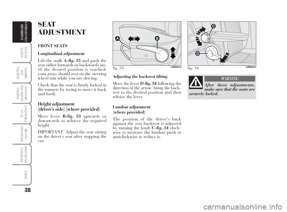
Adjusting the backrest tilting
Move the lever D-fig. 34following the
direction of the arrow: bring the back-
rest to the desired position and then
release the lever.
Lumbar adjustment
(where provided)
The position of the driver’s back
against the seat backrest is adjusted
by turning the knob C-fig. 34clock-
wise to increase the lumbar push or
anticlockwise to reduce it.
SEAT
ADJUSTMENT
FRONT SEATS
Longitudinal adjustment
Lift the stalk A-fig. 33and push the
seat either forwards or backwards un-
til the desired position is reached:
your arms should rest on the steering
wheel rim while you are driving.
Check that the seat is firmly locked in
the runners by trying to move it back
and forth.
Height adjustment
(driver’s side) (where provided)
Move lever B-fig. 33upwards or
downwards to achieve the required
height.
IMPORTANT Adjust the seat sitting
on the driver’s seat after stopping the
car.
fig. 33L0D0041mfig. 34L0D0042m
After these adjustments,
make sure that the seats are
securely locked.
WARNING
038-094 MUSA 1ed GB 11-07-2008 14:10 Pagina 38
Page 40 of 218
39
SAFETY
DEVICES
STARTING
AND
DRIVING
WARNING
LIGHTS AND
MESSAGES
IN AN
EMERGENCY
MAINTENANCE
AND CARE
TECHNICALSPECIFICATIONS
INDEX
DASHBOARD
AND CONTROLS
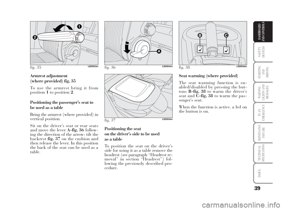
Armrest adjustment
(where provided) fig. 35
To use the armrest bring it from
position1to position 2.
Positioning the passenger’s seat to
be used as a table
Bring the armrest (where provided) in
vertical position.
Sit on the driver’s seat or rear seats
and move the lever A-fig. 36follow-
ing the direction of the arrow: tilt the
backrest fig. 37on the cushion and
then release the lever. In this position
the back of the seat can be used as a
table.Seat warming (where provided)
The seat warming function is en-
abled/disabled by pressing the but-
tonsB-fig. 38to warm the driver’s
seat and C-fig. 38to warm the pas-
senger’s seat.
When the function is active, a led on
the button is on.
Positioning the seat
on the driver’s side to be used
as a table
To position the seat on the driver’s
side for using it as a table remove the
headrest (see paragraph “Headrest re-
moval” in section “Headrest”) fol-
lowing the previously described pro-
cedure.
fig. 35L0D0043mfig. 36L0D0044m
fig. 37L0D0045m
fig. 38L0D0046m
038-094 MUSA 1ed GB 11-07-2008 14:10 Pagina 39
Page 41 of 218

40
SAFETY
DEVICES
STARTING
AND
DRIVING
WARNING
LIGHTS AND
MESSAGES
IN AN
EMERGENCY
MAINTENANCE
AND CARE
TECHNICALSPECIFICATIONS
INDEX
DASHBOARD
AND CONTROLS
Adjusting the backrest tilting
Move levers AorB-fig. 42to adjust
the desired part of the seat. Bring the
seat in the desired position and then
release the lever.
Adjustments from luggage
compartment
Longitudinal adjustment
Move the handles FandG-fig. 41to
adjust the desired part of the seat by
moving it forwards or backwards. REAR SLIDING SEATS
Adjustments from car inside
Longitudinal adjustment
Lift levers A-fig. 39orBto adjust the
desired part of the seat. Then, move
the seat forwards or backwards.
Adjusting the backrest tilting
Move the lever C-fig. 40until the
backrest reaches the desired position
and then release the lever.
To prevent possible irregular move-
ments always push the lever Call the
way down.
fig. 39L0D0047mfig. 40L0D0252m
fig. 41L0D0253m
fig. 42L0D0049m
After these adjustments,
make sure that the seats are
securely locked.
WARNING
038-094 MUSA 1ed GB 11-07-2008 14:10 Pagina 40
Page 42 of 218
41
SAFETY
DEVICES
STARTING
AND
DRIVING
WARNING
LIGHTS AND
MESSAGES
IN AN
EMERGENCY
MAINTENANCE
AND CARE
TECHNICALSPECIFICATIONS
INDEX
DASHBOARD
AND CONTROLS
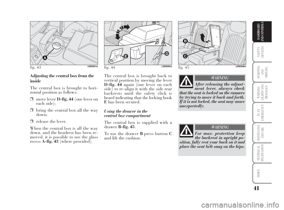
The central box is brought back to
vertical position by moving the lever
D-fig. 44again (one lever on each
side) to re-align it with the side rear
backrests until the safety click is
heard indicating that the locking hook
Ehas been secured.
Using the drawer in the
central box compartment
The central box is supplied with a
drawerB-fig. 45.
To use the drawer Bpress button C
and lift the cushion. Adjusting the central box from the
inside
The central box is brought to hori-
zontal position as follows:
❒move lever D-fig. 44(one lever on
each side);
❒bring the central box all the way
down;
❒release the lever.
When the central box is all the way
down, and the headrest has been re-
moved, it is possible to use the glass
recess A-fig. 43(where provided).
fig. 43L0D0051mfig. 44L0D0050mfig. 45L0D0358m
After releasing the adjust-
ment lever, always check
that the seat is locked on the runners
by trying to move it back and forth.
If it is not locked, the seat may move
unexpectedly.
WARNING
For max. protection keep
the backrest in upright po-
sition, fully rest your back on it and
place the seat belt snug on the hips.
WARNING
038-094 MUSA 1ed GB 11-07-2008 14:10 Pagina 41
Page 43 of 218
42
SAFETY
DEVICES
STARTING
AND
DRIVING
WARNING
LIGHTS AND
MESSAGES
IN AN
EMERGENCY
MAINTENANCE
AND CARE
TECHNICALSPECIFICATIONS
INDEX
DASHBOARD
AND CONTROLS
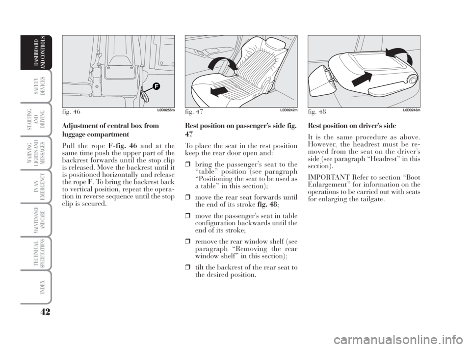
Rest position on driver’s side
It is the same procedure as above.
However, the headrest must be re-
moved from the seat on the driver’s
side (see paragraph “Headrest” in this
section).
IMPORTANT Refer to section “Boot
Enlargement” for information on the
operations to be carried out with seats
for enlarging the tailgate. Rest position on passenger’s side fig.
47
To place the seat in the rest position
keep the rear door open and:
❒bring the passenger’s seat to the
“table” position (see paragraph
“Positioning the seat to be used as
a table” in this section);
❒move the rear seat forwards until
the end of its stroke fig. 48;
❒move the passenger’s seat in table
configuration backwards until the
end of its stroke;
❒remove the rear window shelf (see
paragraph “Removing the rear
window shelf” in this section);
❒tilt the backrest of the rear seat to
the desired position. Adjustment of central box from
luggage compartment
Pull the rope F-fig. 46and at the
same time push the upper part of the
backrest forwards until the stop clip
is released. Move the backrest until it
is positioned horizontally and release
the rope F. To bring the backrest back
to vertical position, repeat the opera-
tion in reverse sequence until the stop
clip is secured.
fig. 46L0D0255mfig. 47L0D0242mfig. 48L0D0243m
038-094 MUSA 1ed GB 11-07-2008 14:10 Pagina 42
Page 44 of 218
43
SAFETY
DEVICES
STARTING
AND
DRIVING
WARNING
LIGHTS AND
MESSAGES
IN AN
EMERGENCY
MAINTENANCE
AND CARE
TECHNICALSPECIFICATIONS
INDEX
DASHBOARD
AND CONTROLS
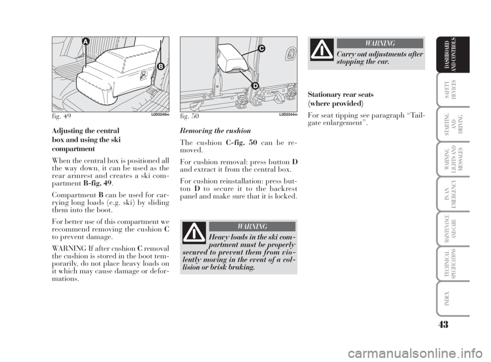
Adjusting the central
box and using the ski
compartment
When the central box is positioned all
the way down, it can be used as the
rear armrest and creates a ski com-
partmentB-fig. 49.
CompartmentBcan be used for car-
rying long loads (e.g. ski) by sliding
them into the boot.
For better use of this compartment we
recommend removing the cushion C
to prevent damage.
WARNING If after cushion Cremoval
the cushion is stored in the boot tem-
porarily, do not place heavy loads on
it which may cause damage or defor-
mations.Removing the cushion
The cushion C-fig. 50can be re-
moved.
For cushion removal: press button D
and extract it from the central box.
For cushion reinstallation: press but-
tonDto secure it to the backrest
panel and make sure that it is locked.
fig. 49L0D0249mfig. 50L0D0344m
Heavy loads in the ski com-
partment must be properly
secured to prevent them from vio-
lently moving in the event of a col-
lision or brisk braking.
WARNING
Carry out adjustments after
stopping the car.
WARNING
Stationary rear seats
(where provided)
For seat tipping see paragraph “Tail-
gate enlargement”.
038-094 MUSA 1ed GB 11-07-2008 14:10 Pagina 43
Page 45 of 218

44
SAFETY
DEVICES
STARTING
AND
DRIVING
WARNING
LIGHTS AND
MESSAGES
IN AN
EMERGENCY
MAINTENANCE
AND CARE
TECHNICALSPECIFICATIONS
INDEX
DASHBOARD
AND CONTROLS
REAR SIDE AND CENTRAL
HEADRESTS (where provided)
Headrests can be adjusted in height.
Headrests are lifted by moving them
upwards until the lock click is heard.
Headrests are lowered by pressing
buttonC-fig. 53.
Headrests are removed (although it is
not required for normal configura-
tions) by pressing button D-fig. 53.
HEADRESTS
FRONT HEADRESTS
Headrests can be adjusted in height.
For height adjustment: pull the head-
rest upwards or push it downwards by
pressing button A-fig. 51. After this
operation is completed, make sure
that the lock click is heard.
Removing the headrest
Press button B-fig. 52to remove the
headrest.
fig. 51L0D0052mfig. 52L0D0237m
If a side bag is fitted, it is
dangerous to use seat cov-
ers that do not belong to the Lin-
eaccessori Lancia range.
WARNING
fig. 53L0D0053m
Travelling without head-
rests can pose a risk for the
passenger.
WARNING
038-094 MUSA 1ed GB 11-07-2008 14:10 Pagina 44
Page 46 of 218
45
SAFETY
DEVICES
STARTING
AND
DRIVING
WARNING
LIGHTS AND
MESSAGES
IN AN
EMERGENCY
MAINTENANCE
AND CARE
TECHNICALSPECIFICATIONS
INDEX
DASHBOARD
AND CONTROLS
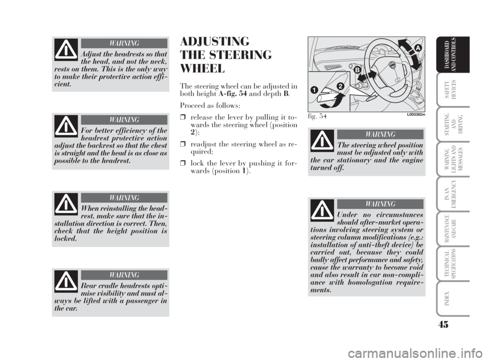
ADJUSTING
THE STEERING
WHEEL
The steering wheel can be adjusted in
both height A-fig. 54and depth B.
Proceed as follows:
❒release the lever by pulling it to-
wards the steering wheel (position
2);
❒readjust the steering wheel as re-
quired;
❒lock the lever by pushing it for-
wards (position 1).
Rear cradle headrests opti-
mise visibility and must al-
ways be lifted with a passenger in
the car.
WARNING
fig. 54L0D0382m
The steering wheel position
must be adjusted only with
the car stationary and the engine
turned off.
WARNING
Under no circumstances
should after-market opera-
tions involving steering system or
steering column modifications (e.g.:
installation of anti-theft device) be
carried out, because they could
badly affect performance and safety,
cause the warranty to become void
and also result in car non-compli-
ance with homologation require-
ments.
WARNING
Adjust the headrests so that
the head, and not the neck,
rests on them. This is the only way
to make their protective action effi-
cient.
WARNING
For better efficiency of the
headrest protective action
adjust the backrest so that the chest
is straight and the head is as close as
possible to the headrest.
WARNING
When reinstalling the head-
rest, make sure that the in-
stallation direction is correct. Then,
check that the height position is
locked.
WARNING
038-094 MUSA 1ed GB 11-07-2008 14:10 Pagina 45
Page 47 of 218
46
SAFETY
DEVICES
STARTING
AND
DRIVING
WARNING
LIGHTS AND
MESSAGES
IN AN
EMERGENCY
MAINTENANCE
AND CARE
TECHNICALSPECIFICATIONS
INDEX
DASHBOARD
AND CONTROLS
Adjust the mirrors after the car has
been stopped and the hand brake en-
gaged.
The electric demisting device of the
mirrors is automatically engaged
when the rear window demister is ac-
tivated.
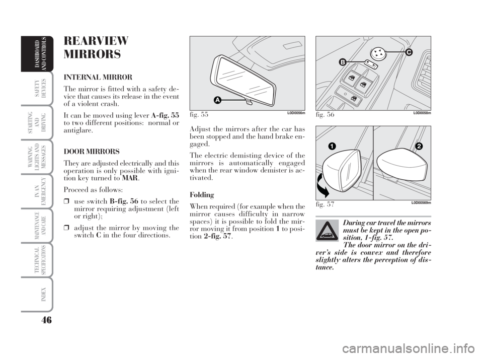
Folding
When required (for example when the
mirror causes difficulty in narrow
spaces) it is possible to fold the mir-
ror moving it from position 1to posi-
tion2-fig. 57.
REARVIEW
MIRRORS
INTERNAL MIRROR
The mirror is fitted with a safety de-
vice that causes its release in the event
of a violent crash.
It can be moved using lever A-fig. 55
to two different positions: normal or
antiglare.
DOOR MIRRORS
They are adjusted electrically and this
operation is only possible with igni-
tion key turned to MAR.
Proceed as follows:
❒use switch B-fig. 56to select the
mirror requiring adjustment (left
or right);
❒adjust the mirror by moving the
switchCin the four directions.
fig. 55L0D0056m
During car travel the mirrors
must be kept in the open po-
sition, 1-fig. 57.
The door mirror on the dri-
ver’s side is convex and therefore
slightly alters the perception of dis-
tance.
fig. 56L0D0058m
fig. 57L0D00569m
038-094 MUSA 1ed GB 11-07-2008 14:10 Pagina 46