wheel Lancia Thema 2014 Owner handbook (in English)
[x] Cancel search | Manufacturer: LANCIA, Model Year: 2014, Model line: Thema, Model: Lancia Thema 2014Pages: 332, PDF Size: 3.46 MB
Page 162 of 332
VEHICLE INFO (CUSTOMER INFORMATIONFEATURES) (for versions/markets, where
provided) .............................174
MESSAGES # ..........................174
TURN MENU OFF .......................174
Uconnect® SETTINGS .....................174
HARD-KEYS ..........................175
SOFT-KEYS ...........................175
CUSTOMER PROGRAMMABLE FEATURES — Uconnect® 8.4 SETTINGS ................175
SOUND SYSTEMS ........................183
NAVIGATION SYSTEM (for versions/markets, where provided) .........................183
SETTING THE ANALOG CLOCK .............184
iPod®/USB/MP3 CONTROL (for vehicles/markets, where provided) .........................184
HARMAN KARDON® Logic7® HIGH PERFORMANCE MULTICHANNEL SURROUND
SOUND SYSTEM WITH DRIVER-SELECTABLE
SURROUND (DSS) (for versions/markets, where
required) ...............................184
STEERING WHEEL AUDIO CONTROLS .......185
RADIO OPERATION .....................185
CDPLAYER...........................185
CD/DVD DISC MAINTENANCE ..............186
RADIO OPERATION AND MOBILE PHONES . . . .186
CLIMATE CONTROLS .....................186
156
Page 167 of 332

8. Tire Pressure Monitoring Tell-
tale LightEach tire, including the
spare (if provided), should
be checked monthly when
cold and inflated to the in-
flation pressure recommended by the
vehicle manufacturer on the vehicle
placard or tire inflation pressure la-
bel.
As an added safety feature, your ve-
hicle has been equipped with a Tire
Pressure Monitoring System (TPMS)
that illuminates a low tire pressure
telltale when one or more of your tires
is significantly under-inflated. Ac-
cordingly, when the low tire pressure
telltale illuminates, you should stop
and check your tires as soon as pos-
sible, and inflate them to the proper
pressure. Driving on a significantly
under-inflated tire causes the tire to
overheat and can lead to tire failure.
Under-inflation also reduces fuel effi-
ciency and tire tread life, and may
affect the vehicle’s handling and stop-
ping ability. Please note that the TPMS is not a
substitute for proper tire mainte-
nance, and it is the driver’s responsi-
bility to maintain correct tire pres-
sure, even if under-inflation has not
reached the level to trigger illumina-
tion of the TPMS low tire pressure
telltale.
Your vehicle has also been equipped
with a TPMS malfunction indicator to
indicate when the system is not oper-
ating properly. The TPMS malfunc-
tion indicator is combined with the
low tire pressure telltale. When the
system detects a malfunction, the tell-
tale will flash for approximately one
minute and then remain continuously
illuminated. This sequence will con-
tinue upon subsequent vehicle start-
ups as long as the malfunction exists.
When the malfunction indicator is il-
luminated, the system may not be
able to detect or signal low tire pres-
sure as intended. TPMS malfunctions
may occur for a variety of reasons,
including the installation of replace-
ment or alternate tires or wheels on
the vehicle that prevent the TPMS
from functioning properly. Alwayscheck the TPMS malfunction telltale
after replacing one or more tires or
wheels on your vehicle, to ensure that
the replacement or alternate tires and
wheels allow the TPMS to continue to
function properly.
CAUTION!
The TPMS has been optimized for
the original equipment tires and
wheels. TPMS pressures and warn-
ing have been established for the
tire size equipped on your vehicle.
Undesirable system operation or
sensor damage may result when us-
ing replacement equipment that is
not of the same size, type, and/or
style. Aftermarket wheels can cause
sensor damage. Do not use tire seal-
ant from a can or balance beads if
your vehicle is equipped with a
TPMS, as damage to the sensors
may result.
161
Page 171 of 332

19. Seat Belt Reminder LightWhen the ignition switch is
first turned to ON/RUN, this
light will turn on for four to
eight seconds as a bulb check. During
the bulb check, if the driver's seat belt
is unbuckled, a chime will sound. Af-
ter the bulb check or when driving, if
the driver or passenger's (for
versions/markets, where provided)
seat belt remains unbuckled, the Seat
Belt Reminder Light will illuminate
and the chime will sound. Refer to
“Occupant Restraints” in “Things To
Know Before Starting Your Vehicle”
for further information.
20. Temperature Gauge
The temperature gauge shows engine
coolant temperature. Any reading
within the normal range indicates
that the engine cooling system is op-
erating satisfactorily.
The gauge pointer will likely indicate
a higher temperature when driving in
hot weather, up mountain grades, or
when towing a trailer. It should not be
allowed to exceed the upper limits of
the normal operating range.CAUTION!
Driving with a hot engine cooling
system could damage your vehicle.
If the temperature gauge reads “H”
pull over and stop the vehicle. Idle
the vehicle with the air conditioner
turned off until the pointer drops
back into the normal range. If the
pointer remains on the “H” and you
hear continuous chimes, turn the
engine off immediately and call an
authorized dealer for service.
WARNING!
A hot engine cooling system is dan-
gerous. You or others could be
badly burned by steam or boiling
coolant. You may want to call an
authorized dealer for service if your
vehicle overheats. If you decide to
look under the hood yourself, see
“Maintaining Your Vehicle”. Fol-
low the warnings under the Cooling
System Pressure Cap paragraph. 21. AWD (All Wheel Drive) Indica-
tor (for versions/ markets, where
provided)
The AWD indicator will illuminate
when All Wheel Drive (AWD) is
activated.
ELECTRONIC VEHICLE
INFORMATION CENTER
(EVIC)
The Electronic Vehicle Information
Center (EVIC) features a driver-
interactive display that is located in
the instrument cluster.
This system allows the driver to select
a variety of useful information by
Electronic Vehicle Information
Center (EVIC)
165
Page 172 of 332

pressing the switches mounted on the
steering wheel. The EVIC consists of
the following:
Radio Info
Fuel Economy Info
Cruise Control Info
Digital Vehicle Speed
Trip Info
Tire Pressure
Vehicle Info
Stored Warning Messages
Turn Menu OFF
The system allows the driver to select
information by pressing the following
buttons mounted on the steering
wheel:UP Button
Press and release the UP
button to scroll upward
through the main menu and
Vehicle Info and Trip Info
sub-menus (Fuel Economy, Vehicle
Info, Tire BAR, Cruise, Messages, Trip
Info, Vehicle Speed, and Turn Menu
OFF) and sub-menus.
DOWN Button
Press and release the
DOWN button to scroll
downward through the
main menu and Vehicle Info
and Trip Info sub-menus (Fuel
Economy, Vehicle Info, Tire BAR,
Cruise, Messages, Trip Info, Vehicle
Speed, and Turn Menu OFF) and
sub-menus.
SELECT Button
Press and release the SE-
LECT button to access the
information screens or sub-
menu screens of a main menu item.
Press and hold the SELECT button for
two seconds to reset displayed/selected
features that can be reset.
BACK Button
Press the BACK button to
return to the main menu
from an info screen or sub-
menu item.
ELECTRONIC VEHICLE
INFORMATION CENTER
(EVIC) DISPLAYS
The EVIC display consists of three
sections:
1. The top line where compass direc-
tion, odometer line and outside tem-
perature are displayed.
NOTE: The system will display
the last known out- side tempera-
ture when starting the vehicle and
may need to be driven several min-
utes before the updated tempera-
ture is displayed. Engine tempera-
ture can also affect the displayed
temperature; therefore, tempera-
ture readings are not updated
when the vehicle is not moving.
2. The main display area where the
menus and pop up messages are dis-
played.
EVIC Steering Wheel Buttons
166
Page 175 of 332
filter to prevent engine damage. Refer
to “Maintenance Procedures/ Drain-
ing Fuel/Water Separator Filter” in
“Maintaining Your Vehicle” for water
drain procedure.
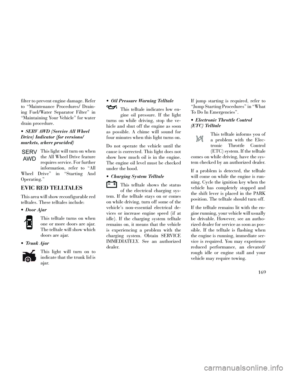
SERV AWD (Service All Wheel
Drive) Indicator (for versions/
markets, where provided)This light will turn on when
the All Wheel Drive feature
requires service. For further
information, refer to “All
Wheel Drive” in “Starting And
Operating.”
EVIC RED TELLTALES
This area will show reconfigurable red
telltales. These telltales include:
Door Ajar
This telltale turns on when
one or more doors are ajar.
The telltale will show which
doors are ajar.
Trunk Ajar
This light will turn on to
indicate that the trunk lid is
ajar. Oil Pressure Warning Telltale
This telltale indicates low en-
gine oil pressure. If the light
turns on while driving, stop the ve-
hicle and shut off the engine as soon
as possible. A chime will sound for
four minutes when this light turns on.
Do not operate the vehicle until the
cause is corrected. This light does not
show how much oil is in the engine.
The engine oil level must be checked
under the hood.
Charging System Telltale
This telltale shows the status
of the electrical charging sys-
tem. If the telltale stays on or comes
on while driving, turn off some of the
vehicle's non-essential electrical de-
vices or increase engine speed (if at
idle). If the charging system telltale
remains on, it means that the vehicle
is experiencing a problem with the
charging system. Obtain SERVICE
IMMEDIATELY. See an authorized
dealer. If jump starting is required, refer to
“Jump Starting Procedures” in “What
To Do In Emergencies”.
Electronic Throttle Control
(ETC) Telltale
This telltale informs you of
a problem with the Elec-
tronic Throttle Control
(ETC) system. If the telltale
comes on while driving, have the sys-
tem checked by an authorized dealer.
If a problem is detected, the telltale
will come on while the engine is run-
ning. Cycle the ignition key when the
vehicle has completely stopped and
the shift lever is placed in the PARK
position. The telltale should turn off.
If the telltale remains lit with the en-
gine running, your vehicle will usually
be drivable. However, see an autho-
rized dealer for service as soon as pos-
sible. If the telltale is flashing when
the engine is running, immediate ser-
vice is required. You may experience
reduced performance, an elevated/
rough idle or engine stall and your
vehicle may require towing.
169
Page 180 of 332
Resetting A Trip Info Function
To Reset any of the three Trip Info
functions, select the function you
want to reset using the UP or DOWN
buttons. Push the SELECT button
until the feature displays zero.
TIRE BAR
Press and release the UP or DOWN
button until “Tire BAR” is high-
lighted in the EVIC. Press and release
the SELECT button and one of the
following will be displayed:
If tire pressure is OK for all tires avehicle ICON is displayed with tire
pressure values in each corner of
the ICON.
If one or more tires have low pres- sure, "Inflate to XXX" is displayed
with the vehicle ICON and the tire
pressure values in each corner of
the ICON.
If the Tire Pressure system requires service, "Service Tire Pressure Sys-
tem" is displayed. Tire pressure is an information only
function and cannot be reset. Press
and release the BACK button to re-
turn to the main menu.
VEHICLE INFO
(CUSTOMER
INFORMATION FEATURES)
(for versions/markets,
where provided)
Press and release the UP or DOWN
button until "Vehicle Info" is high-
lighted in the EVIC. Press and release
the SELECT button and Coolant
Temp will be displayed. Press the UP
or DOWN button to scroll through the
following information displays.
Coolant Temp
Displays the actual coolant tempera-
ture.
Oil Pressure
Displays the actual oil pressure.
Trans Temperature
Displays the actual transmission
temperature. Engine Hours
Displays the number of hours of en-
gine operation.
MESSAGES #
Select from Main Menu using the UP
or DOWN buttons. This feature shows
the number of stored warning mes-
sages (in the # place holder). Pressing
the SELECT button will allow you to
see what the stored messages are.
Pressing the BACK button takes you
back to the Main Menu.
TURN MENU OFF
Select from Main Menu using the
DOWN button. Pressing the SELECT
button blanks the menu display.
Pressing any one of the four steering
wheel buttons brings the menu back.
Uconnect® SETTINGS
The Uconnect® system uses a combi-
nation of soft and hard keys located
on the center of the instrument panel
that allows you to access and change
the customer programmable features.
174
Page 186 of 332
Daytime Running Lights (for
versions/markets, where provided)
When this feature is selected, the
headlights will turn on whenever the
engine is running. To make your se-
lection, touch the Daytime Running
Lights soft-key, until a check-mark
appears next to setting, showing that
setting has been selected. Touch the
back arrow soft-key to return to the
previous menu.
Steering Directed Lights (for
versions/markets, where provided)
When this feature is selected, the
headlights turn relative to a change in
direction of the steering wheel. To
make your selection, touch the Steer-
ing Directed Lights soft-key, until a
check-mark appears next to setting,
showing that setting has been se-
lected. Touch the back arrow soft-key
to return to the previous menu.
Headlight Dipped Beam (Traffic
Changeover) (for versions/markets,
where provided)
Low beam headlights have more con-
trol of upward light and direct most oftheir light downward and either to the
left for right hand drive countries or to
the right for left hand drive countries
to provide safe forward visibility
without excessive glare.
Doors & Locks
After pressing the Doors & Locks soft-
key the following settings will be
available.
Auto Lock
When this feature is selected, all doors
will lock automatically when the ve-
hicle reaches a speed of 24 km/h. To
make your selection, touch the Auto
Lock soft-key, until a check-mark ap-
pears next to setting, showing that
setting has been selected. Touch the
back arrow soft-key to return to the
previous menu.
Auto Unlock On Exit
When this feature is selected, all doors
will unlock when the vehicle is
stopped and the transmission is in the
PARK or NEUTRAL position and the
driver's door is opened. To make your
selection, touch the Auto Unlock On
Exit soft-key, until a check-mark ap-
pears next to setting, showing that
setting has been selected. Touch the
back arrow soft-key to return to the
previous menu.
1st Press Of Key Fob Unlocks
When 1st Press Of Key Fob Unlocks is
selected, only the driver's door will
unlock on the first press of the Remote
Keyless Entry (RKE) transmitter UN-
LOCK button. When 1st Press Of Key
Fob Unlocks is selected, you must
press the RKE transmitter UNLOCK
button twice to unlock the passenger's
doors. When Unlock All Doors On 1st
Press is selected, all of the doors will
unlock on the first press of the RKE
transmitter UNLOCK button.
NOTE: If the vehicle is pro-
grammed 1st Press Of Key Fob Un-
locks, all doors will unlock no
matter which Passive Entry
equipped door handle is grasped.
If 1st Press Of Key Fob Unlocks is
programmed, only the driver’s
door will unlock when the driver’s
door is grasped. With Passive En-
try, if 1st Press Of Key Fob Unlocks
180
Page 191 of 332
Selecting “Audio Surround” through
the DSS modes activates the Harman
Kardon® Logic7® multichannel
surround-sound technology in your
vehicle. The “Video Surround” mode
is described under Driver-Selectable
Surround (DSS). The Video Surround
Mode will only be available for video
media sources (DVDs, Video CDs, or
other video media supported by the
radio). Some audio will sound better
in DSS modes, others in Stereo mode.
When in “Audio Surround” mode,
balance is set automatically. Fader
control is available in surround mode
but should be set to the center position
for optimal surround performance.
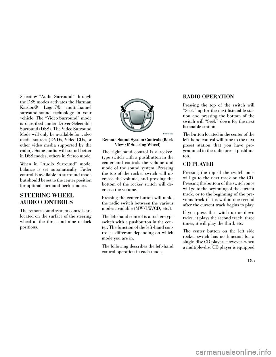
STEERING WHEEL
AUDIO CONTROLS
The remote sound system controls are
located on the surface of the steering
wheel at the three and nine o'clock
positions.The right-hand control is a rocker-
type switch with a pushbutton in the
center and controls the volume and
mode of the sound system. Pressing
the top of the rocker switch will in-
crease the volume, and pressing the
bottom of the rocker switch will de-
crease the volume.
Pressing the center button will make
the radio switch between the various
modes available (MW/LW/CD, etc.).
The left-hand control is a rocker-type
switch with a pushbutton in the cen-
ter. The function of the left-hand con-
trol is different depending on which
mode you are in.
The following describes the left-hand
control operation in each mode.
RADIO OPERATION
Pressing the top of the switch will
“Seek” up for the next listenable sta-
tion and pressing the bottom of the
switch will “Seek” down for the next
listenable station.
The button located in the center of the
left-hand control will tune to the next
preset station that you have pro-
grammed in the radio preset pushbut-
ton.
CD PLAYER
Pressing the top of the switch once
will go to the next track on the CD.
Pressing the bottom of the switch once
will go to the beginning of the current
track, or to the beginning of the pre-
vious track if it is within one second
after the current track begins to play.
If you press the switch up or down
twice, it plays the second track; three
times, it will play the third, etc.
The center button on the left side
rocker switch has no function for a
single-disc CD player. However, when
a multiple-disc CD player is equipped
Remote Sound System Controls (Back
View Of Steering Wheel)
185
Page 195 of 332

11. Driver Temperature Control
Down Button
Provides the driver with independent
temperature control. Push the button
for cooler temperature settings.
NOTE: In Sync mode, this but-
ton will also automatically adjust
the passenger temperature setting
at the same time.
12. Driver Temperature Control Up
Button
Provides the driver with independent
temperature control. Push the button
for warmer temperature settings.
NOTE: In Sync mode, this but-
ton will also automatically adjust
the passenger temperature setting
at the same time.
13. Modes
1. The airflow distribution mode can
be adjusted so air comes from the
instrument panel outlets, floor out-
lets, demist outlets and defrost out-
lets. The Mode settings are as follows: Panel Mode
Air comes from the outlets in
the instrument panel. Each of
these outlets can be individu-
ally adjusted to direct the flow of air.
The air vanes of the center outlets and
outboard outlets can be moved up and
down or side to side to regulate air-
flow direction. There is a shut off
wheel located below the air vanes to
shut off or adjust the amount of air-
flow from these outlets.
Bi-Level Mode Air comes from the instrument
panel outlets and floor outlets.
A slight amount of air is di-
rected through the defrost and side
window demister outlets.
NOTE: BI-LEVEL mode is de-
signed under comfort conditions
to provide cooler air out of the
panel outlets and warmer air from
the floor outlets.
Floor Mode Air comes from the floor out-
lets. A slight amount of air is
directed through the defrost
and side window demister outlets. Mix Mode
Air comes from the floor, de-
frost and side window demist
outlets. This mode works best
in cold or snowy conditions.
Defrost Mode Air comes from the windshield
and side window demist out-
lets. Use Defrost mode with
maximum temperature settings for
best windshield and side window de-
frosting and defogging. When the de-
frost mode is selected, the blower level
will increase.
14. SYNC
Press the Sync soft-key to toggle the
Sync feature On/Off. The Sync indi-
cator is illuminated when this feature
is enabled. Sync is used to synchro-
nize the passenger temperature set-
ting with the driver temperature set-
ting. Changing the passenger
temperature setting while in Sync will
automatically exit this feature.
189
Page 199 of 332

5
STARTING AND OPERATING
STARTING PROCEDURES..................197
KEYLESS ENTER-N-GO™ ...............197
NORMAL STARTING — GASOLINE ENGINE . .197
EXTREME COLD WEATHER (BELOW �29°C) ........................198
IF ENGINE FAILS TO START ..............198
AFTERSTARTING......................199
NORMAL STARTING – DIESEL ENGINE .....199
AUTOMATIC TRANSMISSION ...............201
KEY IGNITION PARK INTERLOCK .........202
BRAKE/TRANSMISSION SHIFT INTERLOCK SYSTEM .............................202
EIGHT-SPEED AUTOMATIC TRANSMISSION – 3.6L ENGINE ..........................202
FIVE-SPEED AUTOMATIC TRANSMISSION – 3.0L DIESEL ENGINE ...................207
AUTOSTICK® (for versions/markets, where provided) ...............................211
OPERATION – 3.6L ENGINE ...............211
OPERATION – 3.0L DIESEL ENGINE ........212
ALL-WHEEL DRIVE (AWD) (for versions/markets, where provided) .........................213
193