key Lancia Voyager 2014 Owner handbook (in English)
[x] Cancel search | Manufacturer: LANCIA, Model Year: 2014, Model line: Voyager, Model: Lancia Voyager 2014Pages: 364, PDF Size: 3.49 MB
Page 28 of 364
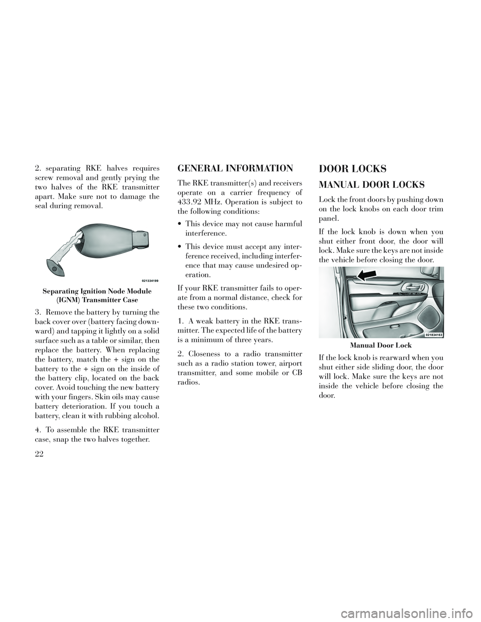
2. separating RKE halves requires
screw removal and gently prying the
two halves of the RKE transmitter
apart. Make sure not to damage the
seal during removal.
3. Remove the battery by turning the
back cover over (battery facing down-
ward) and tapping it lightly on a solid
surface such as a table or similar, then
replace the battery. When replacing
the battery, match the + sign on the
battery to the + sign on the inside of
the battery clip, located on the back
cover. Avoid touching the new battery
with your fingers. Skin oils may cause
battery deterioration. If you touch a
battery, clean it with rubbing alcohol.
4. To assemble the RKE transmitter
case, snap the two halves together.GENERAL INFORMATION
The RKE transmitter(s) and receivers
operate on a carrier frequency of
433.92 MHz. Operation is subject to
the following conditions:
This device may not cause harmfulinterference.
This device must accept any inter- ference received, including interfer-
ence that may cause undesired op-
eration.
If your RKE transmitter fails to oper-
ate from a normal distance, check for
these two conditions.
1. A weak battery in the RKE trans-
mitter. The expected life of the battery
is a minimum of three years.
2. Closeness to a radio transmitter
such as a radio station tower, airport
transmitter, and some mobile or CB
radios.
DOOR LOCKS
MANUAL DOOR LOCKS
Lock the front doors by pushing down
on the lock knobs on each door trim
panel.
If the lock knob is down when you
shut either front door, the door will
lock. Make sure the keys are not inside
the vehicle before closing the door.
If the lock knob is rearward when you
shut either side sliding door, the door
will lock. Make sure the keys are not
inside the vehicle before closing the
door.
Separating Ignition Node Module (IGNM) Transmitter Case
Manual Door Lock
22
Page 29 of 364
WARNING!
For personal security and safetyin the event of a collision, lock the
vehicle doors as you drive as well
as when you park and leave the
vehicle.
When leaving the vehicle, always remove the Key Fob from the ig-
nition and lock your vehicle.
Never leave children alone in a vehicle, or with access to an un-
locked vehicle. Allowing children
to be in a vehicle unattended is
dangerous for a number of rea-
sons. A child or others could be
seriously or fatally injured. Chil-
dren should be warned not to
touch the parking brake, brake
pedal or the shift lever.
(Continued)
WARNING!(Continued)
Do not leave the Key Fob in or
near the vehicle, or in a location
accessible to children, and do not
leave the ignition of a vehicle
equipped with Keyless Enter-N-
Go™ in the ACC or ON/RUN
mode. A child could operate
power windows, other controls, or
move the vehicle.
POWER DOOR LOCKS (for
versions/markets, where
provided)
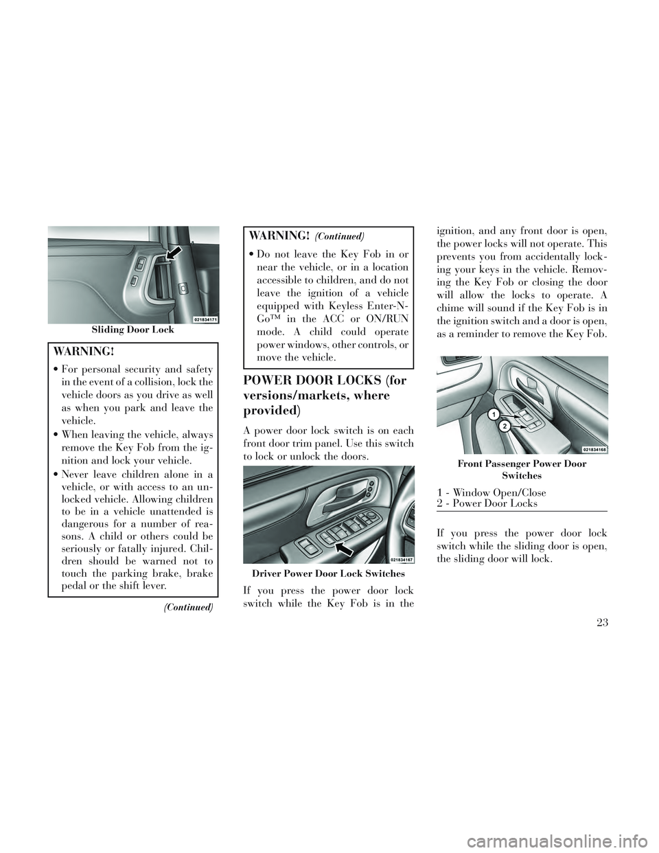
A power door lock switch is on each
front door trim panel. Use this switch
to lock or unlock the doors.
If you press the power door lock
switch while the Key Fob is in the ignition, and any front door is open,
the power locks will not operate. This
prevents you from accidentally lock-
ing your keys in the vehicle. Remov-
ing the Key Fob or closing the door
will allow the locks to operate. A
chime will sound if the Key Fob is in
the ignition switch and a door is open,
as a reminder to remove the Key Fob.
If you press the power door lock
switch while the sliding door is open,
the sliding door will lock.
Sliding Door Lock
Driver Power Door Lock Switches
Front Passenger Power Door
Switches
1 - Window Open/Close
2 - Power Door Locks
23
Page 30 of 364
Automatic Door Locks
When enabled, the door locks will
lock automatically when the vehicle's
speed exceeds 24 km/h. The auto
door lock feature can be enabled or
disabled by your authorized dealer
per written request of the customer.
Please see your authorized dealer for
service.
Unlock Doors Automatically On
Exit (for versions/markets, where
provided)
The Unlock Doors Automatically On
Exit feature unlocks all of the vehicle
doors when any door is opened. This
will occur only after the shift lever has
been shifted into the PARK position,
after the vehicle has been driven (the
shift lever has been shifted out of
PARK and all doors closed).
The Unlock Doors Automatically On
Exit feature will not operate if there is
any manual operation of the power
door locks (lock or unlock).
Refer to “Electronic Vehicle Informa-
tion Center (EVIC)/Personal Settings(Customer-Programmable Fea-
tures)” in “Understanding Your In-
strument Panel” for further informa-
tion.
NOTE: Use the Lock Doors Auto-
matically at 24 km/h and Unlock
Doors Automatically On Exit fea-
tures in accordance with local
laws.
KEYLESS ENTER-N-
GO™
The Passive Entry system is an en-
hancement to the vehicle’s Remote
Keyless Entry (RKE) system and a
feature of Keyless Enter-N-Go™.
This feature allows you to lock and
unlock the vehicle’s door(s) without
having to press the RKE transmitter
lock or unlock buttons.
NOTE:
Passive Entry may be pro-
grammed ON/OFF; refer to
“Electronic Vehicle Information
Center (EVIC)/Personal Settings (Customer-Programmable Fea-
tures)” in “Understanding Your
Instrument Panel” for further
information.
If a Passive Entry door handle has not been used for an ex-
tended period of time, the Pas-
sive Entry feature for the handle
may time out. Pulling the deac-
tivated front door handle will
reactivate the door handle's
Passive Entry feature.
If wearing gloves on your hands, or if it has been raining on the
Passive Entry door handle, the
unlock sensitivity can be af-
fected, resulting in a slower re-
sponse time.
If you unlock the doors using the Passive Entry door handles, but
do NOT pull the handle, the
doors will automatically lock af-
ter 60 seconds.
To Unlock From The Driver's Side:
With a valid Passive Entry RKE
transmitter within 1.5 m of the driv-
er's door handle, grab the driver's
24
Page 31 of 364
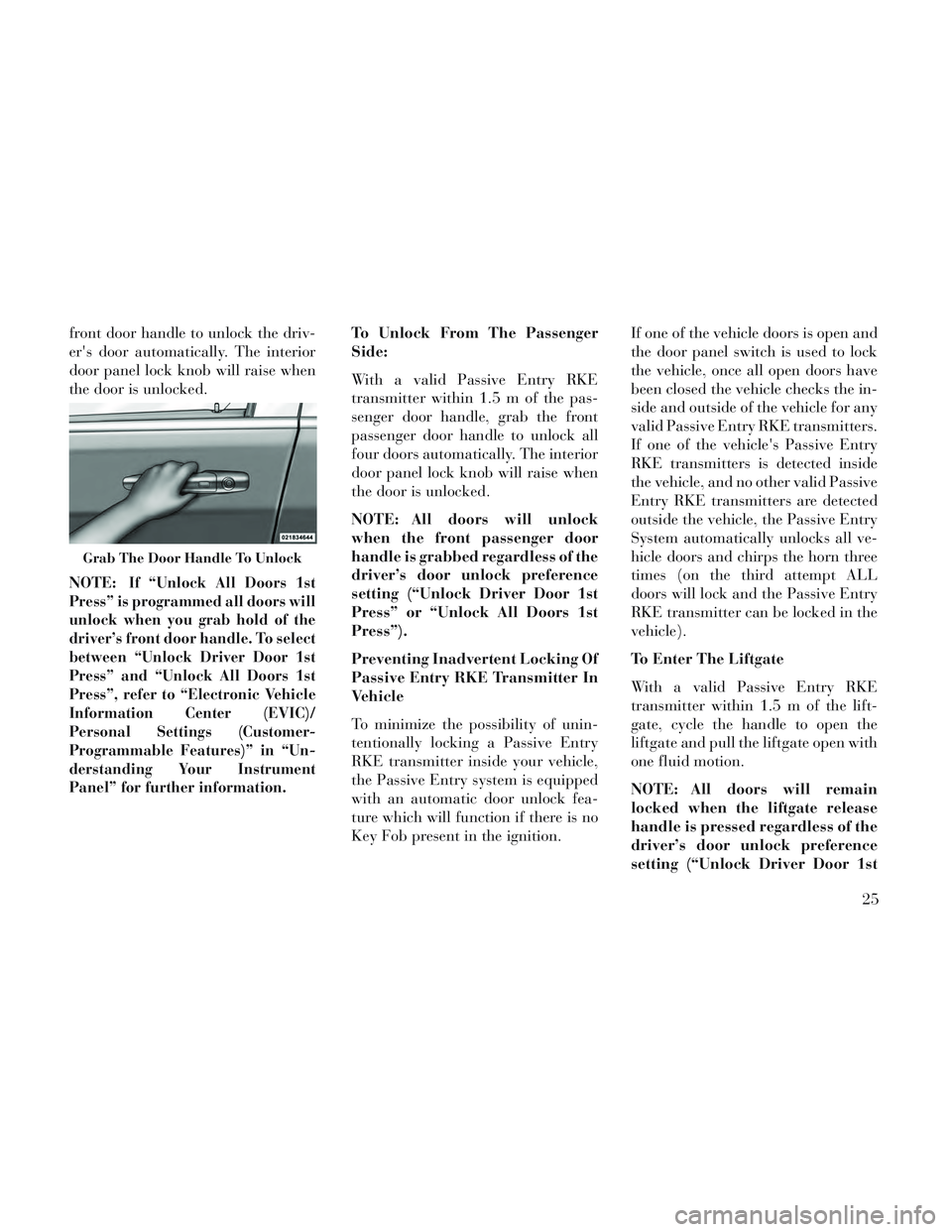
front door handle to unlock the driv-
er's door automatically. The interior
door panel lock knob will raise when
the door is unlocked.
NOTE:
If “Unlock All Doors 1st
Press” is programmed all doors will
unlock when you grab hold of the
driver’s front door handle. To select
between “Unlock Driver Door 1st
Press” and “Unlock All Doors 1st
Press”, refer to “Electronic Vehicle
Information Center (EVIC)/
Personal Settings (Customer-
Programmable Features)” in “Un-
derstanding Your Instrument
Panel” for further information.
To Unlock From The Passenger
Side:
With a valid Passive Entry RKE
transmitter within 1.5 m of the pas-
senger door handle, grab the front
passenger door handle to unlock all
four doors automatically. The interior
door panel lock knob will raise when
the door is unlocked.
NOTE: All doors will unlock
when the front passenger door
handle is grabbed regardless of the
driver’s door unlock preference
setting (“Unlock Driver Door 1st
Press” or “Unlock All Doors 1st
Press”).
Preventing Inadvertent Locking Of
Passive Entry RKE Transmitter In
Vehicle
To minimize the possibility of unin-
tentionally locking a Passive Entry
RKE transmitter inside your vehicle,
the Passive Entry system is equipped
with an automatic door unlock fea-
ture which will function if there is no
Key Fob present in the ignition. If one of the vehicle doors is open and
the door panel switch is used to lock
the vehicle, once all open doors have
been closed the vehicle checks the in-
side and outside of the vehicle for any
valid Passive Entry RKE transmitters.
If one of the vehicle's Passive Entry
RKE transmitters is detected inside
the vehicle, and no other valid Passive
Entry RKE transmitters are detected
outside the vehicle, the Passive Entry
System automatically unlocks all ve-
hicle doors and chirps the horn three
times (on the third attempt ALL
doors will lock and the Passive Entry
RKE transmitter can be locked in the
vehicle).
To Enter The Liftgate
With a valid Passive Entry RKE
transmitter within 1.5 m of the lift-
gate, cycle the handle to open the
liftgate and pull the liftgate open with
one fluid motion.
NOTE: All doors will remain
locked when the liftgate release
handle is pressed regardless of the
driver’s door unlock preference
setting (“Unlock Driver Door 1st
Grab The Door Handle To Unlock
25
Page 37 of 364
power sliding door must be
opened or closed manually.
WARNING!
You, or others, could be injured if
caught in the path of the sliding
door. Make sure the door path is
clear before closing the door.
Power Sliding Side Door Open
Flash
The left and right exterior hazard
lights will flash for 12 seconds when
either sliding door is opened. This will
alert other drivers in the area that
passenger(s) could be entering or ex-
iting the vehicle.
The Sliding Side Door Open Flash can
be enabled or disabled by performing
the following procedure:
1. Place the Key Fob in the ignition
switch.
2. Cycle the ignition switch from ON/
RUN to OFF five times ending in the
ON/RUN position (do not start the
engine). 3. Within 10 seconds of the final
cycle, press the HAZARD switch ON.
4. A single chime will sound to sig-
nify that you have successfully com-
pleted the programming.
You can turn the feature back on by
repeating the previous procedure.
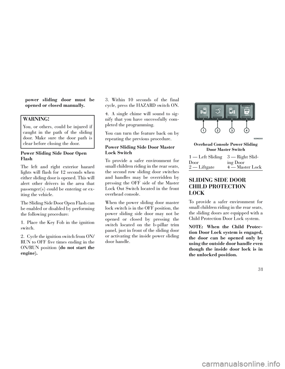
Power Sliding Side Door Master
Lock Switch
To provide a safer environment for
small children riding in the rear seats,
the second row sliding door switches
and handles may be overridden by
pressing the OFF side of the Master
Lock Out Switch located in the front
overhead console.
When the power sliding door master
lock switch is in the OFF position, the
power sliding side door may not be
opened or closed by pressing the
switch located on the b-pillar trim
panel, just in front of the sliding door
or activating the inside power sliding
door handle.
SLIDING SIDE DOOR
CHILD PROTECTION
LOCK
To provide a safer environment for
small children riding in the rear seats,
the sliding doors are equipped with a
Child Protection Door Lock system.
NOTE: When the Child Protec-
tion Door Lock system is engaged,
the door can be opened only by
using the outside door handle even
though the inside door lock is in
the unlocked position.
Overhead Console Power Sliding
Door Master Switch
1 — Left Sliding
Door 3 — Right Slid-
ing Door
2 — Liftgate 4 — Master Lock
31
Page 39 of 364
the “OFF” Master Lock Out
Switch located in the front over-
head console, next to the driver.
WARNING!
Avoid trapping anyone in the ve-
hicle in a collision. Remember that
the sliding doors can only be
opened from the outside door
handle or the switches located on
the b-pillar trim panel just in front
of the power sliding door when the
Child Protection Door Locks are
engaged.
To Disengage the Child Protection
Door Lock
1. Open the sliding side door.
2. Slide the Child Protection Door
Lock control outward (away from the
vehicle) to disengage the Child Pro-
tection Door Lock.
3. Repeat Steps 1 and 2 on the oppo-
site sliding door (for versions/
markets, where provided). NOTE:
After setting the Child Protec-
tion Door Lock system, always
test the door from the inside to
make certain it is in the desired
position.
The power sliding side door switches will not open the power
sliding doors if the vehicle is in
gear or the vehicle speed is
above 0 km/h.
The power sliding door will op- erate from the outside door
handle, the RKE transmitter, the
switches on the overhead con-
sole, or the switches located on
the b-pillar trim panel just in
front of the power sliding door
when the shift lever is in PARK,
regardless of the child lock lever
position.
LIFTGATE
On vehicles equipped with power
locks, the liftgate can be unlocked
using the Remote Keyless Entry (RKE) transmitter button, or by acti-
vating the power door lock switches
located on the front doors.
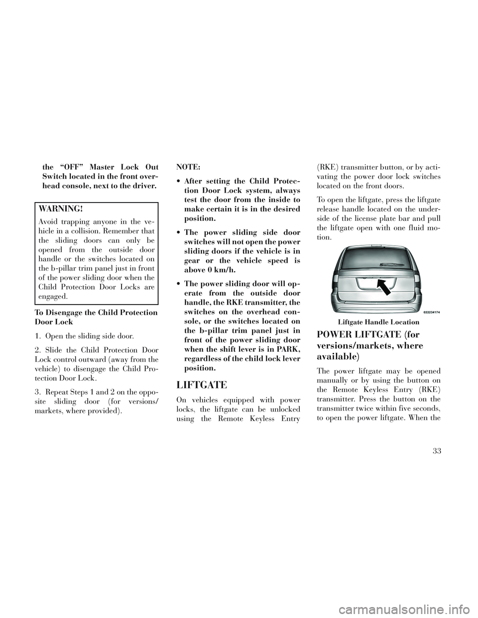
To open the liftgate, press the liftgate
release handle located on the under-
side of the license plate bar and pull
the liftgate open with one fluid mo-
tion.
POWER LIFTGATE (for
versions/markets, where
available)
The power liftgate may be opened
manually or by using the button on
the Remote Keyless Entry (RKE)
transmitter. Press the button on the
transmitter twice within five seconds,
to open the power liftgate. When the
Liftgate Handle Location
33
Page 50 of 364
system whenever the ignition switch is
in the START or ON/RUN position. If
the key is in the LOCK position, in the
ACC position, or not in the ignition,
the Active Hood system is not on and
the Active Hood will not deploy.
The EPPM contains a backup power
supply system that may deploy the
actuators even if the battery loses
power or it becomes disconnected
prior to deployment.
Service Active Hood System
If the EPPM has deployed the Active
Hood, or if it detects a malfunction in
any part of the system, it turns on the
Air Bag Warning Light and it will
display the “SERVICE ACTIVE
HOOD” message in the Electronic Ve-
hicle Information Center (EVIC), for
versions/markets, where provided. A
single chime will sound if the Air Bag
Warning Light comes on again after
initial startup. It also includes diag-
nostics that will illuminate the Air Bag
Warning Light if a malfunction is
noted that could affect the Active
Hood system. The diagnostics also re-
cord the nature of the malfunction. Ifthe Air Bag Warning Light is illumi-
nated, or if “SERVICE ACTIVE
HOOD” appears in the EVIC, see
your authorized dealer.
In the event of an Active Hood deploy-
ment, the vehicle should be serviced
by an authorized dealer. The hood
hinges must be serviced and the ac-
tuator assemblies replaced to restore
system functionality.
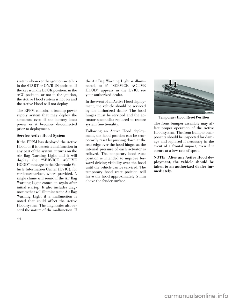
Following an Active Hood deploy-
ment, the hood position can be tem-
porarily reset by pushing down at the
rear edge over the hood hinges as the
internal pressure of each actuator is
relieved. The temporary hood reset
position is intended to improve for-
ward driving visibility over the hood
until the vehicle can be serviced. The
temporary hood reset position will
leave the hood approximately 5 mm
above the fender surface.
The front bumper assembly may af-
fect proper operation of the Active
Hood system. The front bumper com-
ponents should be inspected for dam-
age and replaced if necessary in the
event of a frontal impact, even if it
occurs at a low rate of speed.
NOTE: After any Active Hood de-
ployment, the vehicle should be
taken to an authorized dealer im-
mediately.
Temporary Hood Reset Position
44
Page 57 of 364
Air Bags are not expected to reduce
the risk of injury in rear, side, or roll-
over collisions.
The Advanced Front Air Bags will not
deploy in all frontal collisions, includ-
ing some that may produce substan-
tial vehicle damage — for example,
some pole collisions, truck under-
rides, and angle offset collisions. On
the other hand, depending on the type
and location of impact, Advanced
Front Air Bags may deploy in crashes
with little vehicle front-end damage
but that produce a severe initial decel-
eration.
The side air bags will not deploy in all
side collisions. Side air bag deploy-
ment will depend on the severity and
type of collision.
Because air bag sensors measure ve-
hicle deceleration over time, vehicle
speed and damage by themselves are
not good indicators of whether or not
an air bag should have deployed.
Seat belts are necessary for your pro-
tection in all collisions, and also areneeded to help keep you in position,
away from an inflating air bag.
The ORC monitors the readiness of
the electronic parts of the air bag sys-
tem whenever the ignition switch is in
the START or ON/RUN position. If
the key is in the OFF position, in the
ACC position, or not in the ignition,
the air bag system is not on and the air
bags will not inflate.
The ORC contains a backup power
supply system that may deploy the air
bags even if the battery loses power or
it becomes disconnected prior to de-
ployment.
Also, the ORC turns on the
Air Bag Warning Light in
the instrument panel for
approximately four to eight
seconds for a self-check when the ig-
nition is first turned on. After the self-
check, the Air Bag Warning Light will
turn off. If the ORC detects a mal-
function in any part of the system, it
turns on the Air Bag Warning Light,
either momentarily or continuously. A
single chime will sound if the light
comes on again after initial startup. It also includes diagnostics that will
illuminate the instrument cluster Air
Bag Warning Light if a malfunction is
noted that could affect the air bag
system. The diagnostics also record
the nature of the malfunction.
WARNING!
Ignoring the Air Bag Warning Light
in your instrument panel could
mean you won't have the air bags to
protect you in a collision. If the light
does not come on as a bulb check
when the ignition is first turned on,
stays on after you start the vehicle,
or if it comes on as you drive, have
an authorized dealer service the air
bag system immediately.
Driver And Passenger Advanced
Front Air Bag Inflator Units
The Driver and Passenger Advanced
Front Air Bag Inflator Units are lo-
cated in the center of the steering
wheel and on the right side of the
instrument panel. When the ORC de-
tects a collision requiring the Ad-
vanced Front Air Bags, it signals the
51
Page 59 of 364
Front And Side Impact Sensors
In front and side impacts, impact sen-
sors can aid the ORC in determining
appropriate response to impact
events.
Enhanced Accident Response
System
In the event of an impact causing air
bag deployment, if the communica-
tion network remains intact, and the
power remains intact, depending on
the nature of the event the ORC will
determine whether to have the En-
hanced Accident Response System
perform the following functions:
Cut off fuel to the engine.
Flash hazard lights as long as thebattery has power or until the igni-
tion is cycled off.
Turn on the interior lights, which remain on as long as the battery has
power or until the ignition key is
removed.
Unlock the doors automatically.
In order to reset the Enhanced Acci-
dent Response System functions after an event, the ignition switch must be
changed from IGN ON to IGN OFF.
If A Deployment Occurs
The Advanced Front Air Bags are de-
signed to deflate immediately after
deployment.
NOTE: Front and/or side air bags
will not deploy in all collisions.
This does not mean something is
wrong with the air bag system.
If you do have a collision which de-
ploys the air bags, any or all of the
following may occur:
The nylon air bag material may
sometimes cause abrasions and/or
skin reddening to the driver and
front passenger as the air bags de-
ploy and unfold. The abrasions are
similar to friction rope burns or
those you might get sliding along a
carpet or gymnasium floor. They
are not caused by contact with
chemicals. They are not permanent and normally heal quickly. How-
ever, if you haven't healed signifi-
cantly within a few days, or if you
have any blistering, see your doctor
immediately.
As the air bags deflate, you may see some smoke-like particles. The
particles are a normal by-product
of the process that generates the
non-toxic gas used for air bag infla-
tion. These airborne particles may
irritate the skin, eyes, nose, or
throat. If you have skin or eye irri-
tation, rinse the area with cool wa-
ter. For nose or throat irritation,
move to fresh air. If the irritation
continues, see your doctor. If these
particles settle on your clothing,
follow the garment manufacturer's
instructions for cleaning.
Do not drive your vehicle after the air
bags have deployed. If you are in-
volved in another collision, the air
bags will not be in place to protect
you.
53
Page 63 of 364
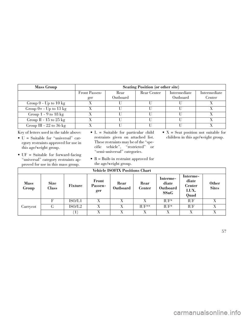
Mass GroupSeating Position (or other site)
Front Passen- ger Rear
Outboard Rear Center Intermediate
OutboardIntermediate
Center
Group0-Upto10kg XUUU X
G ro u p 0+ -U p to 13 kgXUUU X
Group1-9to18kg XUUU X
G ro u p II - 15 to 25 kgXUUU X
G ro u p III - 22 to 36 kgXUUU X
Key of letters used in the table above:
U = Suitable for “universal” cat- egory restraints approved for use in
this age/weight group.
UF = Suitable for forward-facing “universal” category restraints ap-
proved for use in this mass group. L = Suitable for particular child
restraints given on attached list.
These restraints may be of the “spe-
cific vehicle”, “restricted” or
“semi-universal” categories.
B = Built-in restraint approved for the age/weight group. X = Seat position not suitable for
children in this age/weight group.
Vehicle ISOFIX Positions Chart
Mass
Group Size
Class Fixture Front
Passen- ger Rear
Outboard Rear
Center Interme-
diate
Outboard SSnG Interme-
diate
Center LUX.
Quad Other
Sites
Carrycot F ISO/L1 X
XX IUF* IUF X
G ISO/L2 X X IUF** IUF* IUF X
( 1 )XXXXX X
57