key Lancia Voyager 2014 Owner handbook (in English)
[x] Cancel search | Manufacturer: LANCIA, Model Year: 2014, Model line: Voyager, Model: Lancia Voyager 2014Pages: 364, PDF Size: 3.49 MB
Page 147 of 364

instrument cluster will actuate a
single chime, once per ignition cycle,
and it will display the “PARKSENSE
UNAVAILABLE WIPE REAR SEN-
SORS” or the “PARKSENSE UN-
AVAILABLE SERVICE REQUIRED”
message. Refer to “Electronic Vehicle
Information Center (EVIC)” in “Un-
derstanding Your Instrument Panel”
for further information. When the
shift lever is moved to REVERSE and
the system has detected a faulted con-
dition, the EVIC will display the
"PARKSENSE UNAVAILABLE
WIPE REAR SENSORS" or
"PARKSENSE UNAVAILABLE SER-
VICE REQUIRED" message for as
long as the vehicle is in REVERSE.
Under this condition, ParkSense will
not operate.
If “PARKSENSE UNAVAILABLE
WIPE REAR SENSORS” appears in
the Electronic Vehicle Information
Center (EVIC) make sure the outer
surface and the underside of the rear
fascia/bumper is clean and clear ofsnow, ice, mud, dirt or other obstruc-
tion and then cycle the ignition. If the
message continues to appear, see an
authorized dealer.
If “PARKSENSE UNAVAILABLE
SERVICE REQUIRED” appears in
the EVIC, see an authorized dealer.
CLEANING THE PARK
ASSIST SYSTEM
Clean the sensors with water, car
wash soap and a soft cloth. Do not use
rough or hard cloths. Do not scratch
or poke the sensors. Otherwise, you
could damage the sensors.
PARKSENSE® SYSTEM
USAGE PRECAUTIONS
NOTE:
Ensure that the rear bumper is
free of snow, ice, mud, dirt and
debris to keep the ParkSense®
system operating properly.
Jackhammers, large trucks, and other vibrations could affect the
performance of ParkSense®. When you turn ParkSense® off,
the instrument cluster will dis-
play “PARK ASSIST SYSTEM
OFF.” Furthermore, once you
turn ParkSense® off, it remains
off until you turn it on again,
even if you cycle the ignition key.
When you move the shift lever to the REVERSE position and
ParkSense® is turned off, the
EVIC will display “PARK AS-
SIST SYSTEM OFF” message for
as long as the vehicle is in
REVERSE.
ParkSense®, when on, will re- duce the radio volume when it is
sounding a tone.
Clean the ParkSense® sensors regularly, taking care not to
scratch or damage them. The
sensors must not be covered
with ice, snow, slush, mud, dirt
or debris. Failure to do so can
result in the system not working
properly. The ParkSense® sys-
tem might not detect an obstacle
behind the fascia/bumper, or it
141
Page 150 of 364
WARNING!
Drivers must be careful when back-
ing up even when using the
ParkView® Rear Back Up Camera.
Always check carefully behind your
vehicle, and be sure to check for
pedestrians, animals, other ve-
hicles, obstructions, or blind spots
before backing up. You are respon-
sible for the safety of your sur-
roundings and must continue to
pay attention while backing up.
Failure to do so can result in serious
injury or death.
CAUTION!
To avoid vehicle damage,ParkView® should only be used
as a parking aid. The camera is
unable to view every obstacle or
object in your drive path.
(Continued)
CAUTION!(Continued)
To avoid vehicle damage, the ve-
hicle must be driven slowly when
using ParkView® to be able to stop
in time when an obstacle is seen. It
is recommended that the driver
look frequently over his/her shoul-
der when using ParkView®.
NOTE: If snow, ice, mud, or any
foreign substance builds up on the
camera lens, clean the lens, rinse
with water, and dry with a soft
cloth. Do not cover the lens.
TURNING PARKVIEW® ON
OR OFF — WITH
NAVIGATION/
MULTIMEDIA RADIO
1. Press the “menu” hard-key.
2. Select “system setup” soft-key.
3. Press the “camera setup” soft-key.
4. Enable or disable the rear camera
feature by selecting “enable rear cam-
era in reverse” soft-key.
5. Press the “save” soft-key.
TURNING PARKVIEW® ON
OR OFF — WITHOUT
NAVIGATION/
MULTIMEDIA RADIO
1. Press the “menu” hard-key.
2. Select “system setup” soft-key.
3. Enable or disable the rear camera
feature by selecting “enable rear cam-
era in reverse” soft-key.
OVERHEAD CONSOLES
FRONT OVERHEAD
CONSOLE
Two versions of the overhead console
are available. The base front overhead
console model featured fixed incan-
descent courtesy/reading lights, flip-
down sunglass storage and conversa-
tion mirror. The premium front
overhead console model features a
LED focused light that illuminates
the instrument panel cupholders, two
swiveling LED lights, flip-down sun-
glass storage, conversation mirror,
optional power sliding door switches
and an optional power liftgate switch.
144
Page 151 of 364

NOTE: Premium sunroof console
models include all of above except
sunglass storage.
COURTESY/INTERIOR
LIGHTING
At the forward end of the console are
two courtesy lights (standard dome
light has two buttons). The lights turn
on when a front door, a sliding door or
the liftgate is opened. If your vehicle is
equipped with Remote Keyless Entry
(RKE) the lights will also turn on
when the UNLOCK button on the
RKE transmitter is pressed.
The courtesy lights also function as
reading lights. Press in on each lens to
turn these lights on while inside the
vehicle. Press a second time to turn
each light off. You may adjust thedirection of these lights by pressing
the outside ring, which is identified
with four directional arrows (LED
lamps only).
The area around the instrument panel
cupholders is also illuminated from a
light in the overhead console (premium
console only). This light is turned on
when the headlight switch is on, and
will adjust in brightness when the dim-
mer control is rotated up or down.
SUNGLASS STORAGE
(NON-SUNROOF ONLY)
At the front of the overhead console, a
compartment is provided for the stor-
age of two pairs of sunglasses.
From the closed position, press the
door latch to open the compartment.
The door will slowly rotate to the full
open position.
From this position, the door can be
fully closed or, by rotating upward
about 3/4 of the way and releasing,
positioned for conversation mirror
use.
NOTE: From the “conversation
mirror” position, the door can only
be closed.
Overhead Console
Over Door Latch
Full Open Position
Conversation Mirror Position
145
Page 152 of 364

To return to the full open position, the
door must first be closed and then
opened by pressing the latch again to
release.
REAR COURTESY/
READING LIGHTS (for
versions/markets, where
provided)
The overhead console has two sets of
courtesy lights. The lights turn on
when a front door, a sliding door or
the liftgate is opened. If your vehicle is
equipped with Remote Keyless Entry
(RKE) the lights will also turn on
when the UNLOCK button on the
RKE transmitter is pressed.
The courtesy lights also function as
reading lights. Press in on each lens to
turn these lights on while inside the
vehicle. Press the lens a second time to
turn each light off. You may adjust the
direction of these lights by pressing
the outside ring, which is identified
with four directional arrows.REAR OVERHEAD
CONSOLES (for
versions/markets, where
provided)
The rear overhead storage system is
available in two versions: with or
without sunroof.
An additional LED at the front of the
rear console shines down on the front
foot-well area while in courtesy mode,
for added convenience.Rear Console Halo Lighting
The rear overhead console has re-
cessed halo lighting around the pe-
rimeter of the console base. This fea-
ture provides additional lighting
options while traveling and is con-
trolled by the headlight switch. Refer
to “Lights/Halo Lights (for versions/
markets, where provided)” in “Un-
derstanding The Features Of Your Ve-
hicle” for further information.
Reading LightsOverhead Compartment Features
1 — DVD15 — Storage
2 — Rear HVAC 6 — DVD1
3 — Interior
Lights 7 — Interior
Lights
4 — Storage 8 —
Halo Light-
ing
1(for versions/markets, where
equipped)
146
Page 153 of 364
POWER SUNROOF (for
versions/markets, where
provided)
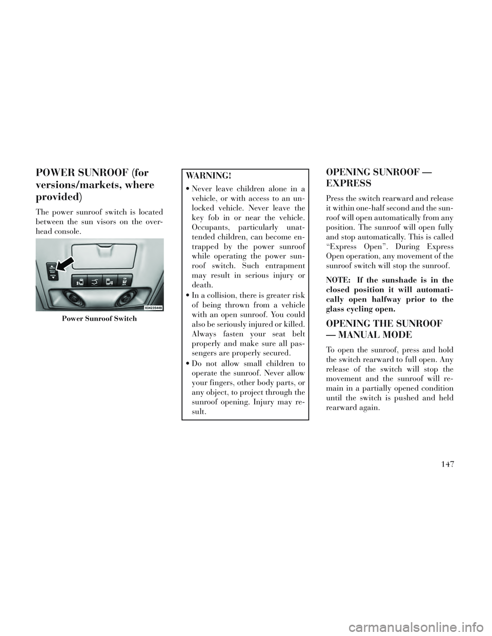
The power sunroof switch is located
between the sun visors on the over-
head console.
WARNING!
Never leave children alone in avehicle, or with access to an un-
locked vehicle. Never leave the
key fob in or near the vehicle.
Occupants, particularly unat-
tended children, can become en-
trapped by the power sunroof
while operating the power sun-
roof switch. Such entrapment
may result in serious injury or
death.
In a collision, there is greater risk of being thrown from a vehicle
with an open sunroof. You could
also be seriously injured or killed.
Always fasten your seat belt
properly and make sure all pas-
sengers are properly secured.
Do not allow small children to operate the sunroof. Never allow
your fingers, other body parts, or
any object, to project through the
sunroof opening. Injury may re-
sult.
OPENING SUNROOF —
EXPRESS
Press the switch rearward and release
it within one-half second and the sun-
roof will open automatically from any
position. The sunroof will open fully
and stop automatically. This is called
“Express Open”. During Express
Open operation, any movement of the
sunroof switch will stop the sunroof.
NOTE: If the sunshade is in the
closed position it will automati-
cally open halfway prior to the
glass cycling open.
OPENING THE SUNROOF
— MANUAL MODE
To open the sunroof, press and hold
the switch rearward to full open. Any
release of the switch will stop the
movement and the sunroof will re-
main in a partially opened condition
until the switch is pushed and held
rearward again.
Power Sunroof Switch
147
Page 156 of 364
Each of these outlets can support 160
Watts (13 Amps). Do not exceed 160
Watts (13 Amps) for each of these
outlets.
The power outlets include tethered
caps, labeled with a key or battery
symbol indicating the power source.
The power outlet, located on the lower
instrument panel, is powered directly
from the battery. Items plugged into
this power outlet may discharge the
battery and/or prevent the engine
from starting.WARNING!
To avoid serious injury or death:
Only devices designed for use inthis type of outlet should be in-
serted into any 12 Volt outlet.
Do not touch with wet hands.
Close the lid when not in use and while driving the vehicle.
If this outlet is mishandled, it may cause an electric shock and fail-
ure.
CAUTION!
Many accessories that can beplugged in draw power from the
vehicle's battery, even when not
in use (i.e., cellular phones, etc.).
Eventually, if plugged in long
enough, the vehicle's battery will
discharge sufficiently to degrade
battery life and/or prevent the
engine from starting.
(Continued)
CAUTION!(Continued)
Accessories that draw higherpower (i.e., coolers, vacuum
cleaners, lights, etc.), will de-
grade the battery even more
quickly. Only use these intermit-
tently and with greater caution.
After the use of high power draw accessories, or long periods of the
vehicle not being started (with
accessories still plugged in), the
vehicle must be driven a suffi-
cient length of time to allow the
alternator to recharge the vehi-
cle's battery.
Power outlets are designed for ac- cessory plugs only. Do not hang
any type of accessory or accessory
bracket from the plug. Improper
use of the power outlet can cause
damage.
SMOKERS PACKAGE KIT
With the optional authorized dealer-
installed Smokers Package Kit, a re-
movable ash receiver is inserted into
one of the two cupholders in the cen-
ter front instrument panel. To install
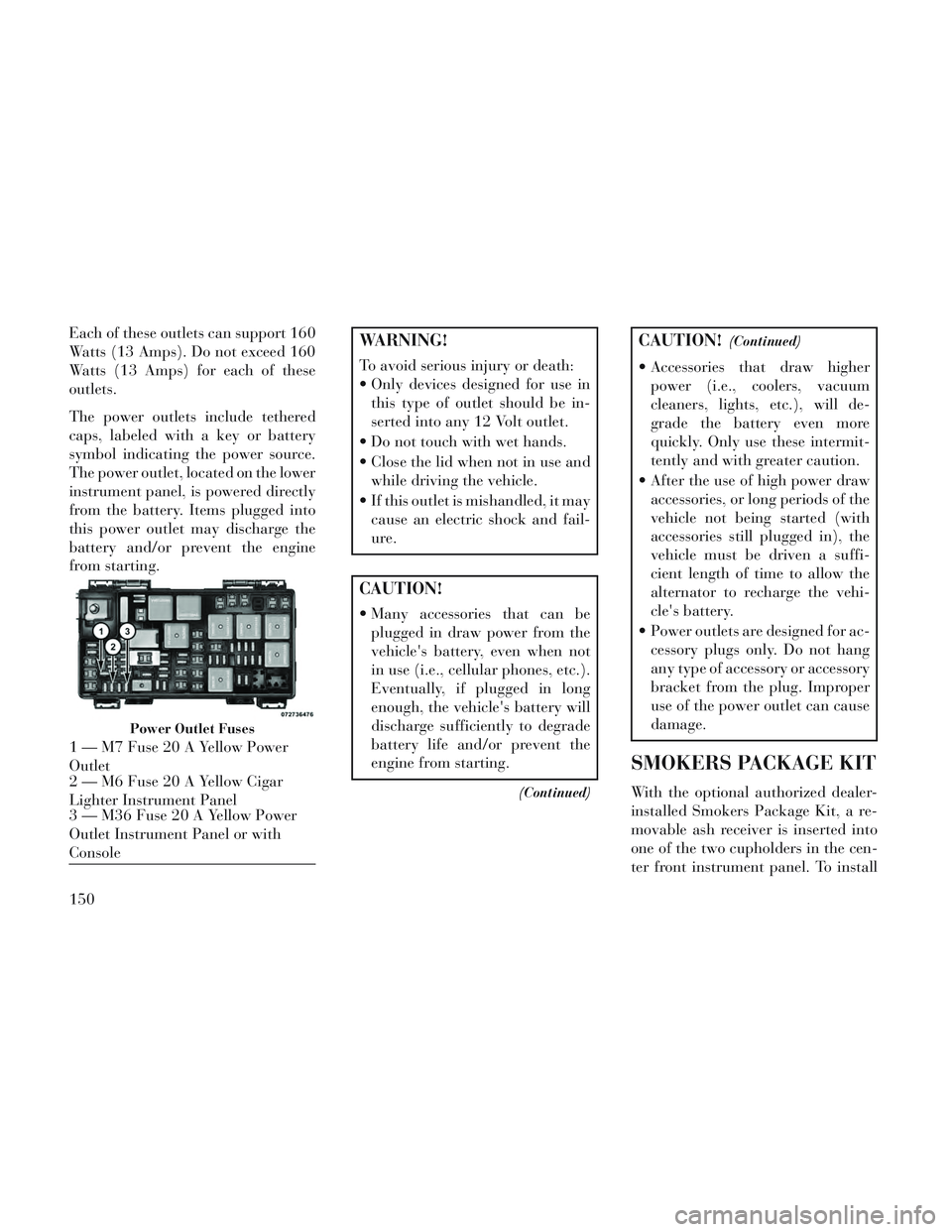
Power Outlet Fuses
1 — M7 Fuse 20 A Yellow Power
Outlet
2 — M6 Fuse 20 A Yellow Cigar
Lighter Instrument Panel
3 — M36 Fuse 20 A Yellow Power
Outlet Instrument Panel or with
Console
150
Page 166 of 364
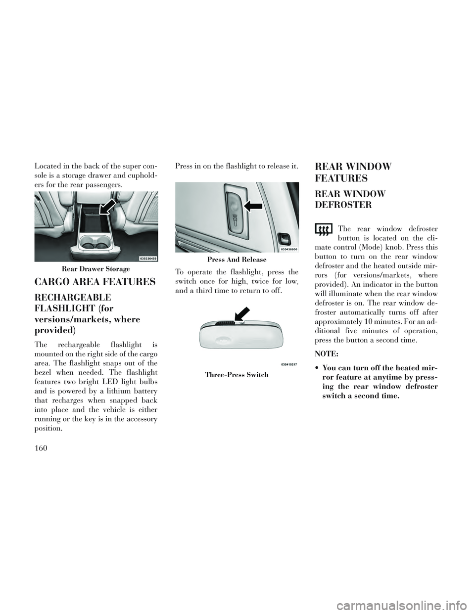
Located in the back of the super con-
sole is a storage drawer and cuphold-
ers for the rear passengers.
CARGO AREA FEATURES
RECHARGEABLE
FLASHLIGHT (for
versions/markets, where
provided)
The rechargeable flashlight is
mounted on the right side of the cargo
area. The flashlight snaps out of the
bezel when needed. The flashlight
features two bright LED light bulbs
and is powered by a lithium battery
that recharges when snapped back
into place and the vehicle is either
running or the key is in the accessory
position.Press in on the flashlight to release it.
To operate the flashlight, press the
switch once for high, twice for low,
and a third time to return to off.
REAR WINDOW
FEATURES
REAR WINDOW
DEFROSTER
The rear window defroster
button is located on the cli-
mate control (Mode) knob. Press this
button to turn on the rear window
defroster and the heated outside mir-
rors (for versions/markets, where
provided). An indicator in the button
will illuminate when the rear window
defroster is on. The rear window de-
froster automatically turns off after
approximately 10 minutes. For an ad-
ditional five minutes of operation,
press the button a second time.
NOTE:
You can turn off the heated mir- ror feature at anytime by press-
ing the rear window defroster
switch a second time.
Rear Drawer Storage
Press And Release
Three-Press Switch
160
Page 172 of 364
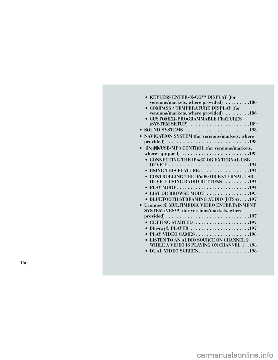
KEYLESS ENTER-N-GO™ DISPLAY (forversions/markets, where provided) .........186
COMPASS / TEMPERATURE DISPLAY (for versions/markets, where provided) .........186
CUSTOMER-PROGRAMMABLE FEATURES (SYSTEM SETUP) ..................... .189
SOUND SYSTEMS ....................... .193
NAVIGATION SYSTEM (for versions/markets, where provided) .............................. .193
iPod®/USB/MP3 CONTROL (for versions/markets, where equipped) ........................ .193
CONNECTING THE iPod® OR EXTERNAL USB DEVICE ............................. .194
USING THIS FEATURE ...................194
CONTROLLING THE iPod® OR EXTERNAL USB DEVICE USING RADIO BUTTONS ..........194
PLAY MODE .......................... .194
LIST OR BROWSE MODE ................195
BLUETOOTH STREAMING AUDIO (BTSA) . . . .197
Uconnect® MULTIMEDIA VIDEO ENTERTAINMENT SYSTEM (VES™) (for versions/markets, where
provided) .............................. .197
GETTING STARTED .................... .197
Blu-ray® PLAYER ..................... .197
PLAY VIDEO GAMES ................... .198
LISTEN TO AN AUDIO SOURCE ON CHANNEL 2
WHILE A VIDEO IS PLAYING ON CHANNEL 1 . .198
DUAL VIDEO SCREEN ...................198
166
Page 174 of 364

INFORMATION MODE DISPLAY...........209
NUMERIC KEYPAD MENU ................209
DISC MENU .......................... .209
DISPLAY SETTINGS ................... .209
LISTENING TO AUDIO WITH THE SCREEN CLOSED ............................. .210
DISC FORMATS ....................... .210
DISPLAY ............................ .213
PRODUCT AGREEMENT .................215
STEERING WHEEL AUDIO CONTROLS .......217
RADIO OPERATION .................... .218
CDPLAYER...........................218
CD/DVD DISC MAINTENANCE ..............218
RADIO OPERATION AND MOBILE PHONES . . . .218
CLIMATE CONTROLS .................... .219
AUTOMATIC TEMPERATURE CONTROL (ATC) ............................... .219
SUMMER OPERATION ...................224
WINTER OPERATION ...................225
VACATION/STORAGE ...................225
WINDOW FOGGING ................... .225
OUTSIDE AIR INTAKE ...................225
A/CAIRFILTER .......................225
OPERATING TIPS ..................... .225
168
Page 180 of 364
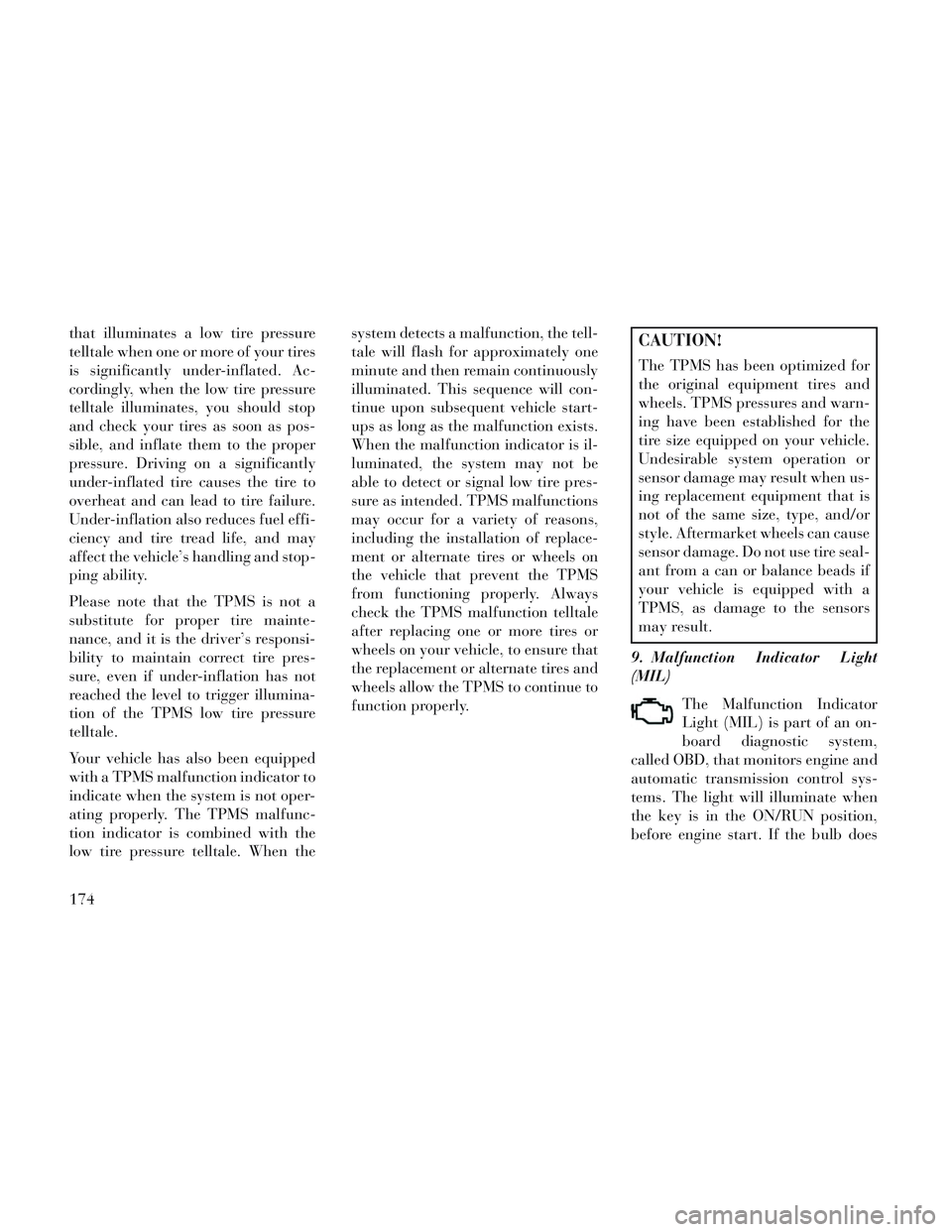
that illuminates a low tire pressure
telltale when one or more of your tires
is significantly under-inflated. Ac-
cordingly, when the low tire pressure
telltale illuminates, you should stop
and check your tires as soon as pos-
sible, and inflate them to the proper
pressure. Driving on a significantly
under-inflated tire causes the tire to
overheat and can lead to tire failure.
Under-inflation also reduces fuel effi-
ciency and tire tread life, and may
affect the vehicle’s handling and stop-
ping ability.
Please note that the TPMS is not a
substitute for proper tire mainte-
nance, and it is the driver’s responsi-
bility to maintain correct tire pres-
sure, even if under-inflation has not
reached the level to trigger illumina-
tion of the TPMS low tire pressure
telltale.
Your vehicle has also been equipped
with a TPMS malfunction indicator to
indicate when the system is not oper-
ating properly. The TPMS malfunc-
tion indicator is combined with the
low tire pressure telltale. When thesystem detects a malfunction, the tell-
tale will flash for approximately one
minute and then remain continuously
illuminated. This sequence will con-
tinue upon subsequent vehicle start-
ups as long as the malfunction exists.
When the malfunction indicator is il-
luminated, the system may not be
able to detect or signal low tire pres-
sure as intended. TPMS malfunctions
may occur for a variety of reasons,
including the installation of replace-
ment or alternate tires or wheels on
the vehicle that prevent the TPMS
from functioning properly. Always
check the TPMS malfunction telltale
after replacing one or more tires or
wheels on your vehicle, to ensure that
the replacement or alternate tires and
wheels allow the TPMS to continue to
function properly.CAUTION!
The TPMS has been optimized for
the original equipment tires and
wheels. TPMS pressures and warn-
ing have been established for the
tire size equipped on your vehicle.
Undesirable system operation or
sensor damage may result when us-
ing replacement equipment that is
not of the same size, type, and/or
style. Aftermarket wheels can cause
sensor damage. Do not use tire seal-
ant from a can or balance beads if
your vehicle is equipped with a
TPMS, as damage to the sensors
may result.
9. Malfunction Indicator Light
(MIL) The Malfunction Indicator
Light (MIL) is part of an on-
board diagnostic system,
called OBD, that monitors engine and
automatic transmission control sys-
tems. The light will illuminate when
the key is in the ON/RUN position,
before engine start. If the bulb does
174