sensor LAND ROVER DISCOVERY 1999 Workshop Manual
[x] Cancel search | Manufacturer: LAND ROVER, Model Year: 1999, Model line: DISCOVERY, Model: LAND ROVER DISCOVERY 1999Pages: 1529, PDF Size: 34.8 MB
Page 670 of 1529
REAR AXLE
REPAIRS 51-5
REPAIRS
Differential - assembly
$% 51.15.01
Remove
1.Raise rear of vehicle.
WARNING: Do not work on or under a
vehicle supported only by a jack. Always
support the vehicle on safety stands.
2.Drain oil from differential.
+ MAINTENANCE, PROCEDURES,
Front and rear axle.
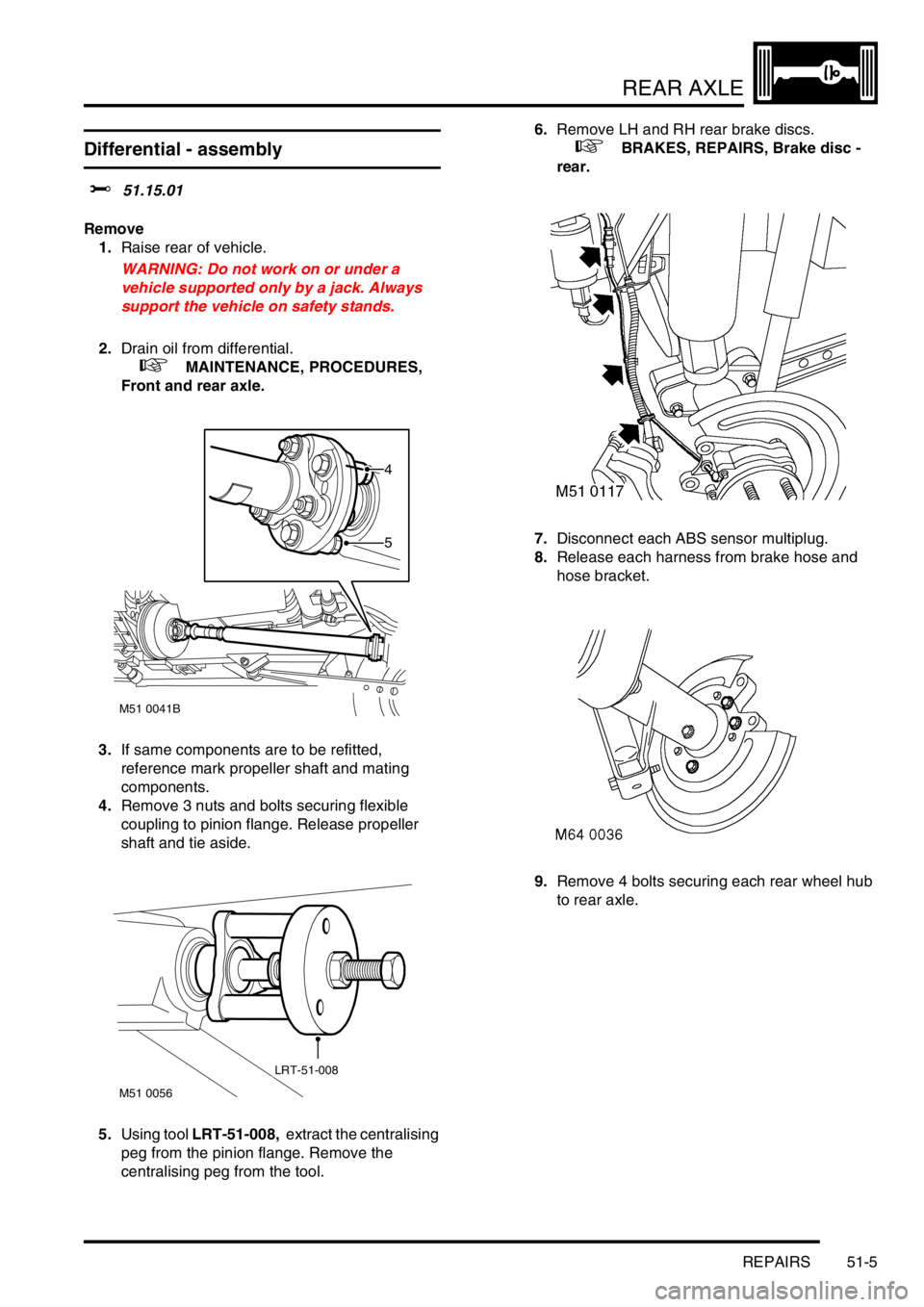
3.If same components are to be refitted,
reference mark propeller shaft and mating
components.
4.Remove 3 nuts and bolts securing flexible
coupling to pinion flange. Release propeller
shaft and tie aside.
5.Using tool LRT-51-008, extract the centralising
peg from the pinion flange. Remove the
centralising peg from the tool.6.Remove LH and RH rear brake discs.
+ BRAKES, REPAIRS, Brake disc -
rear.
7.Disconnect each ABS sensor multiplug.
8.Release each harness from brake hose and
hose bracket.
9.Remove 4 bolts securing each rear wheel hub
to rear axle.
M51 0041B
5
4
M51 0056
LRT-51-008
Page 671 of 1529
REAR AXLE
51-6 REPAIRS
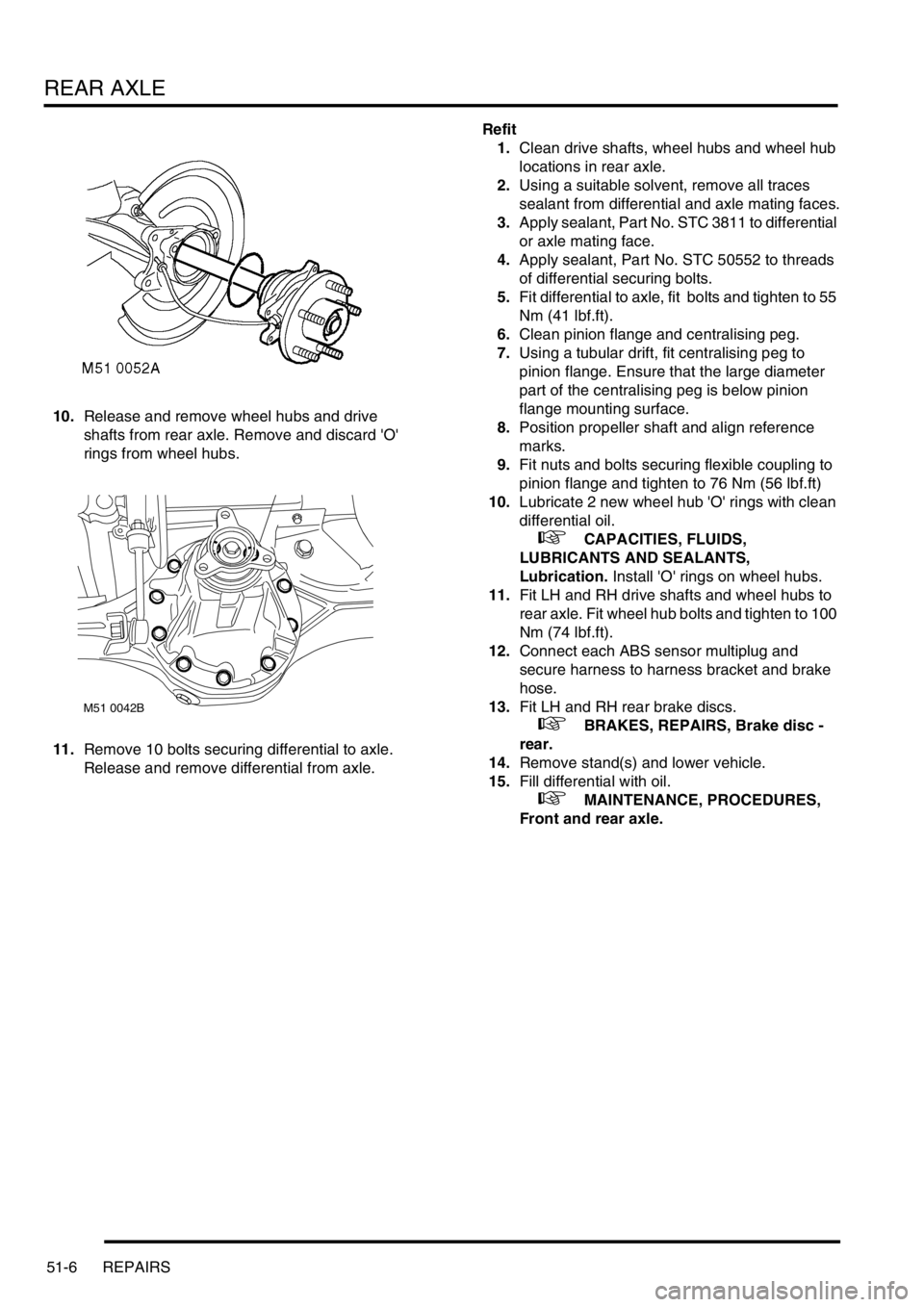
10.Release and remove wheel hubs and drive
shafts from rear axle. Remove and discard 'O'
rings from wheel hubs.
11.Remove 10 bolts securing differential to axle.
Release and remove differential from axle. Refit
1.Clean drive shafts, wheel hubs and wheel hub
locations in rear axle.
2.Using a suitable solvent, remove all traces
sealant from differential and axle mating faces.
3.Apply sealant, Part No. STC 3811 to differential
or axle mating face.
4.Apply sealant, Part No. STC 50552 to threads
of differential securing bolts.
5.Fit differential to axle, fit bolts and tighten to 55
Nm (41 lbf.ft).
6.Clean pinion flange and centralising peg.
7.Using a tubular drift, fit centralising peg to
pinion flange. Ensure that the large diameter
part of the centralising peg is below pinion
flange mounting surface.
8.Position propeller shaft and align reference
marks.
9.Fit nuts and bolts securing flexible coupling to
pinion flange and tighten to 76 Nm (56 lbf.ft)
10.Lubricate 2 new wheel hub 'O' rings with clean
differential oil.
+ CAPACITIES, FLUIDS,
LUBRICANTS AND SEALANTS,
Lubrication. Install 'O' rings on wheel hubs.
11.Fit LH and RH drive shafts and wheel hubs to
rear axle. Fit wheel hub bolts and tighten to 100
Nm (74 lbf.ft).
12.Connect each ABS sensor multiplug and
secure harness to harness bracket and brake
hose.
13.Fit LH and RH rear brake discs.
+ BRAKES, REPAIRS, Brake disc -
rear.
14.Remove stand(s) and lower vehicle.
15.Fill differential with oil.
+ MAINTENANCE, PROCEDURES,
Front and rear axle.
M51 0042B
Page 682 of 1529
FRONT AXLE
DESCRIPTION AND OPERATION 54-3
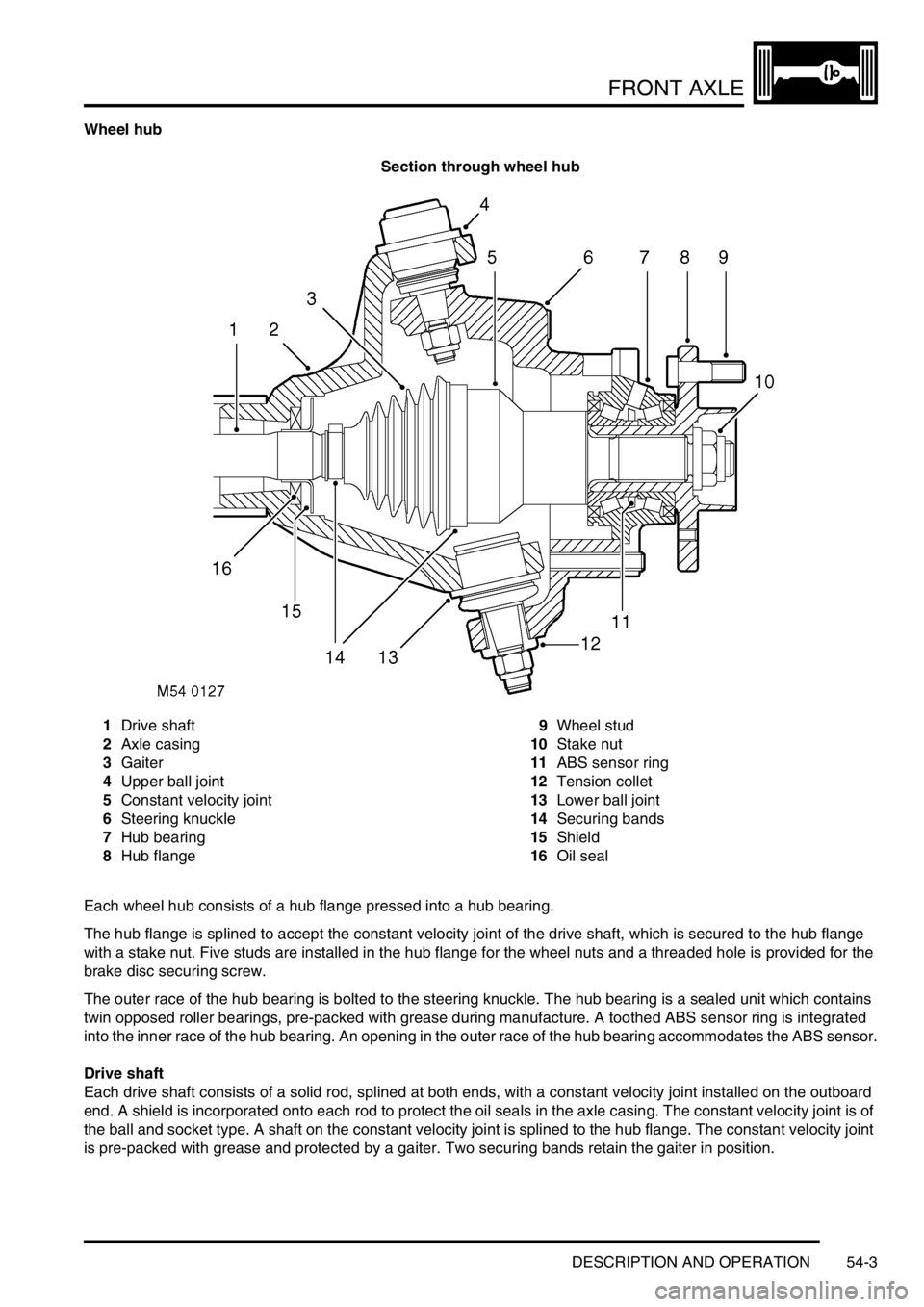
Wheel hub
Section through wheel hub
1Drive shaft
2Axle casing
3Gaiter
4Upper ball joint
5Constant velocity joint
6Steering knuckle
7Hub bearing
8Hub flange9Wheel stud
10Stake nut
11ABS sensor ring
12Tension collet
13Lower ball joint
14Securing bands
15Shield
16Oil seal
Each wheel hub consists of a hub flange pressed into a hub bearing.
The hub flange is splined to accept the constant velocity joint of the drive shaft, which is secured to the hub flange
with a stake nut. Five studs are installed in the hub flange for the wheel nuts and a threaded hole is provided for the
brake disc securing screw.
The outer race of the hub bearing is bolted to the steering knuckle. The hub bearing is a sealed unit which contains
twin opposed roller bearings, pre-packed with grease during manufacture. A toothed ABS sensor ring is integrated
into the inner race of the hub bearing. An opening in the outer race of the hub bearing accommodates the ABS sensor.
Drive shaft
Each drive shaft consists of a solid rod, splined at both ends, with a constant velocity joint installed on the outboard
end. A shield is incorporated onto each rod to protect the oil seals in the axle casing. The constant velocity joint is of
the ball and socket type. A shaft on the constant velocity joint is splined to the hub flange. The constant velocity joint
is pre-packed with grease and protected by a gaiter. Two securing bands retain the gaiter in position.
Page 684 of 1529
FRONT AXLE
REPAIRS 54-5
REPAIRS
Differential - assembly
$% 54.10.01
Remove
1.Raise front of vehicle.
WARNING: Do not work on or under a
vehicle supported only by a jack. Always
support the vehicle on safety stands.
2.Remove front road wheels.
3.Drain oil from differential.
+ MAINTENANCE, PROCEDURES,
Front and rear axle.
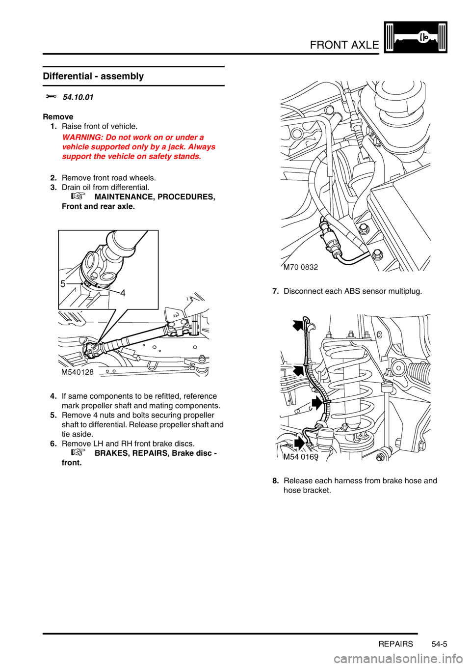
4.If same components to be refitted, reference
mark propeller shaft and mating components.
5.Remove 4 nuts and bolts securing propeller
shaft to differential. Release propeller shaft and
tie aside.
6.Remove LH and RH front brake discs.
+ BRAKES, REPAIRS, Brake disc -
front.7.Disconnect each ABS sensor multiplug.
8.Release each harness from brake hose and
hose bracket.
Page 685 of 1529
FRONT AXLE
54-6 REPAIRS
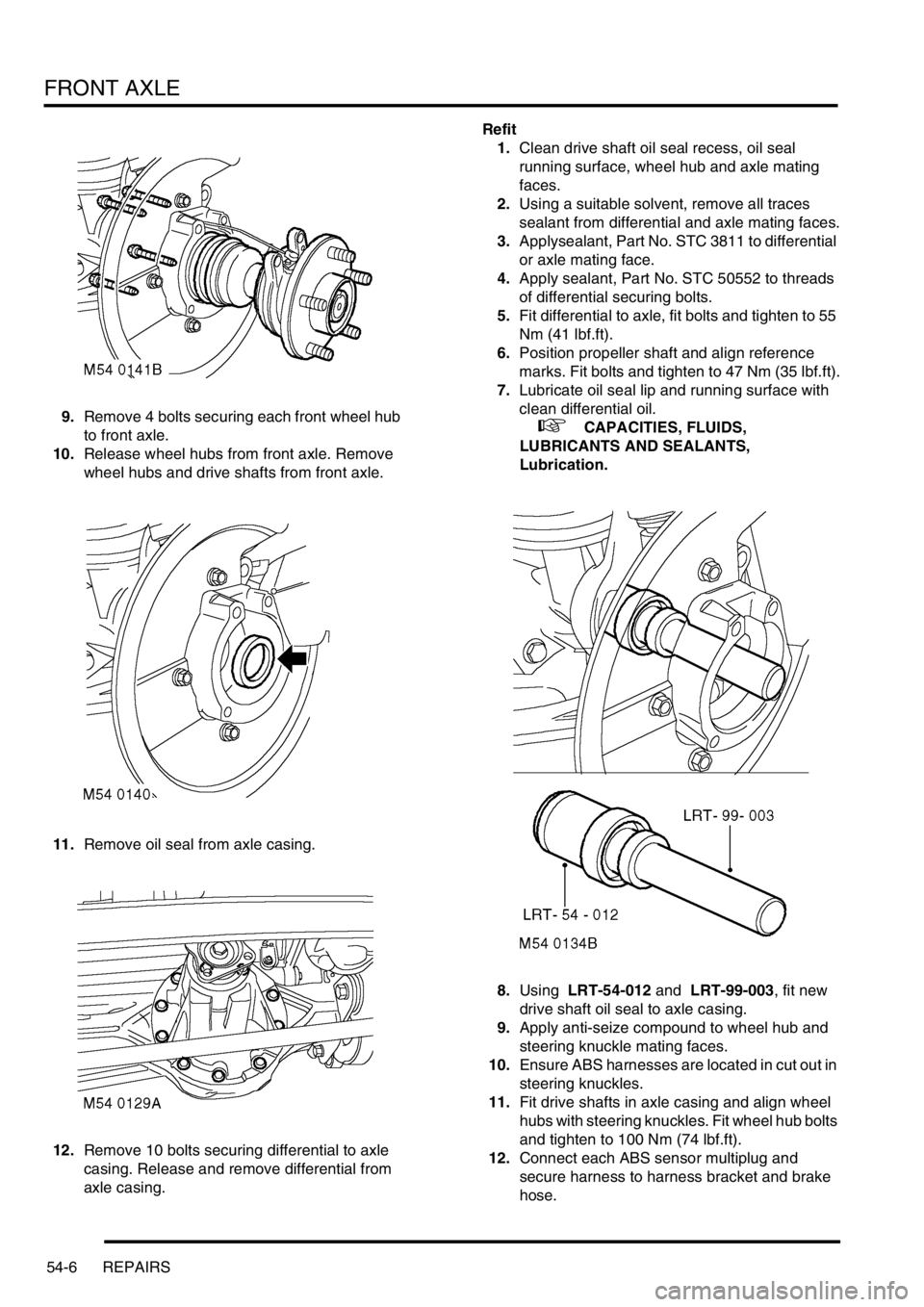
9.Remove 4 bolts securing each front wheel hub
to front axle.
10.Release wheel hubs from front axle. Remove
wheel hubs and drive shafts from front axle.
11.Remove oil seal from axle casing.
12.Remove 10 bolts securing differential to axle
casing. Release and remove differential from
axle casing.Refit
1.Clean drive shaft oil seal recess, oil seal
running surface, wheel hub and axle mating
faces.
2.Using a suitable solvent, remove all traces
sealant from differential and axle mating faces.
3.Applysealant, Part No. STC 3811 to differential
or axle mating face.
4.Apply sealant, Part No. STC 50552 to threads
of differential securing bolts.
5.Fit differential to axle, fit bolts and tighten to 55
Nm (41 lbf.ft).
6.Position propeller shaft and align reference
marks. Fit bolts and tighten to 47 Nm (35 lbf.ft).
7.Lubricate oil seal lip and running surface with
clean differential oil.
+ CAPACITIES, FLUIDS,
LUBRICANTS AND SEALANTS,
Lubrication.
8.Using LRT-54-012 and LRT-99-003, fit new
drive shaft oil seal to axle casing.
9.Apply anti-seize compound to wheel hub and
steering knuckle mating faces.
10.Ensure ABS harnesses are located in cut out in
steering knuckles.
11.Fit drive shafts in axle casing and align wheel
hubs with steering knuckles. Fit wheel hub bolts
and tighten to 100 Nm (74 lbf.ft).
12.Connect each ABS sensor multiplug and
secure harness to harness bracket and brake
hose.
Page 688 of 1529
FRONT AXLE
REPAIRS 54-9
Seal - oil - front axle casing
$% 54.15.04
Remove
1.Raise front of vehicle.
WARNING: Do not work on or under a
vehicle supported only by a jack. Always
support the vehicle on safety stands.
2.Remove road wheel.
3.Remove front brake disc.
+ BRAKES, REPAIRS, Brake disc -
front.
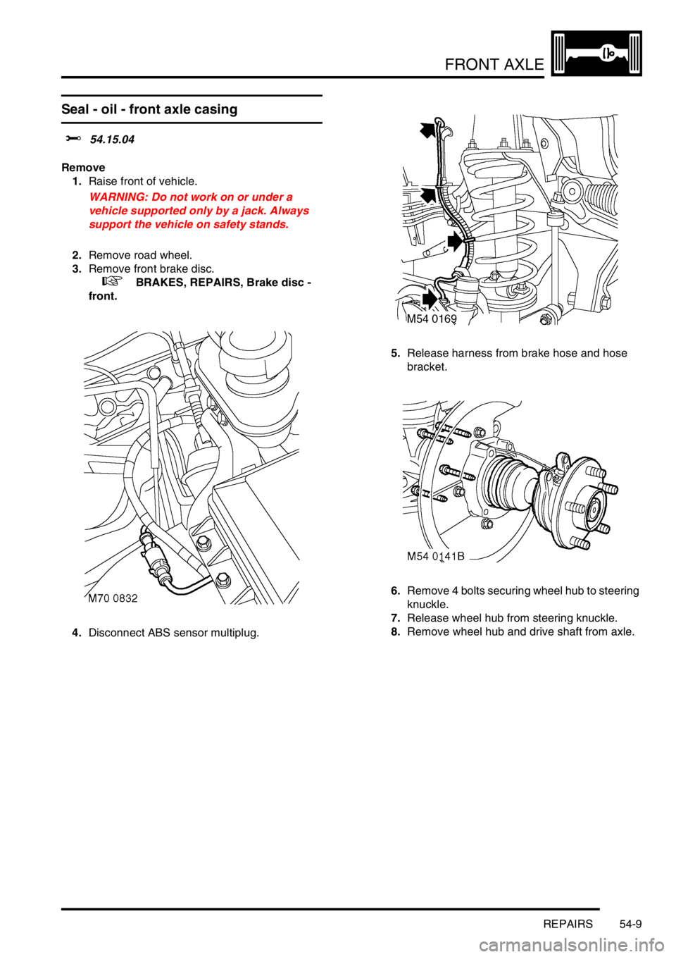
4.Disconnect ABS sensor multiplug.5.Release harness from brake hose and hose
bracket.
6.Remove 4 bolts securing wheel hub to steering
knuckle.
7.Release wheel hub from steering knuckle.
8.Remove wheel hub and drive shaft from axle.
Page 689 of 1529
FRONT AXLE
54-10 REPAIRS
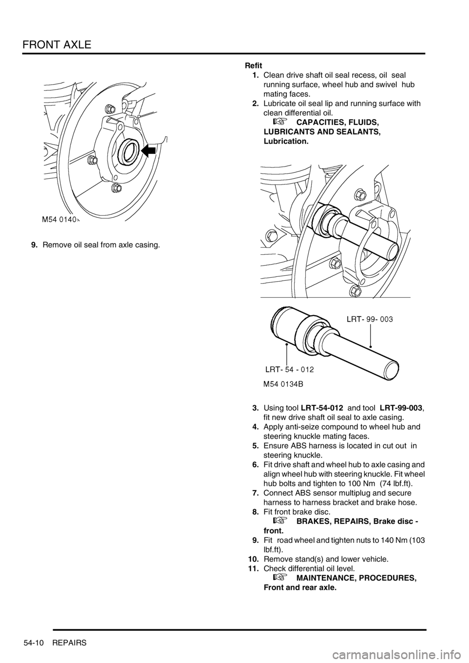
9.Remove oil seal from axle casing.Refit
1.Clean drive shaft oil seal recess, oil seal
running surface, wheel hub and swivel hub
mating faces.
2.Lubricate oil seal lip and running surface with
clean differential oil.
+ CAPACITIES, FLUIDS,
LUBRICANTS AND SEALANTS,
Lubrication.
3.Using tool LRT-54-012 and tool LRT-99-003,
fit new drive shaft oil seal to axle casing.
4.Apply anti-seize compound to wheel hub and
steering knuckle mating faces.
5.Ensure ABS harness is located in cut out in
steering knuckle.
6.Fit drive shaft and wheel hub to axle casing and
align wheel hub with steering knuckle. Fit wheel
hub bolts and tighten to 100 Nm (74 lbf.ft).
7.Connect ABS sensor multiplug and secure
harness to harness bracket and brake hose.
8.Fit front brake disc.
+ BRAKES, REPAIRS, Brake disc -
front.
9.Fit road wheel and tighten nuts to 140 Nm (103
lbf.ft).
10.Remove stand(s) and lower vehicle.
11.Check differential oil level.
+ MAINTENANCE, PROCEDURES,
Front and rear axle.
Page 712 of 1529
STEERING
ADJUSTMENTS 57-19
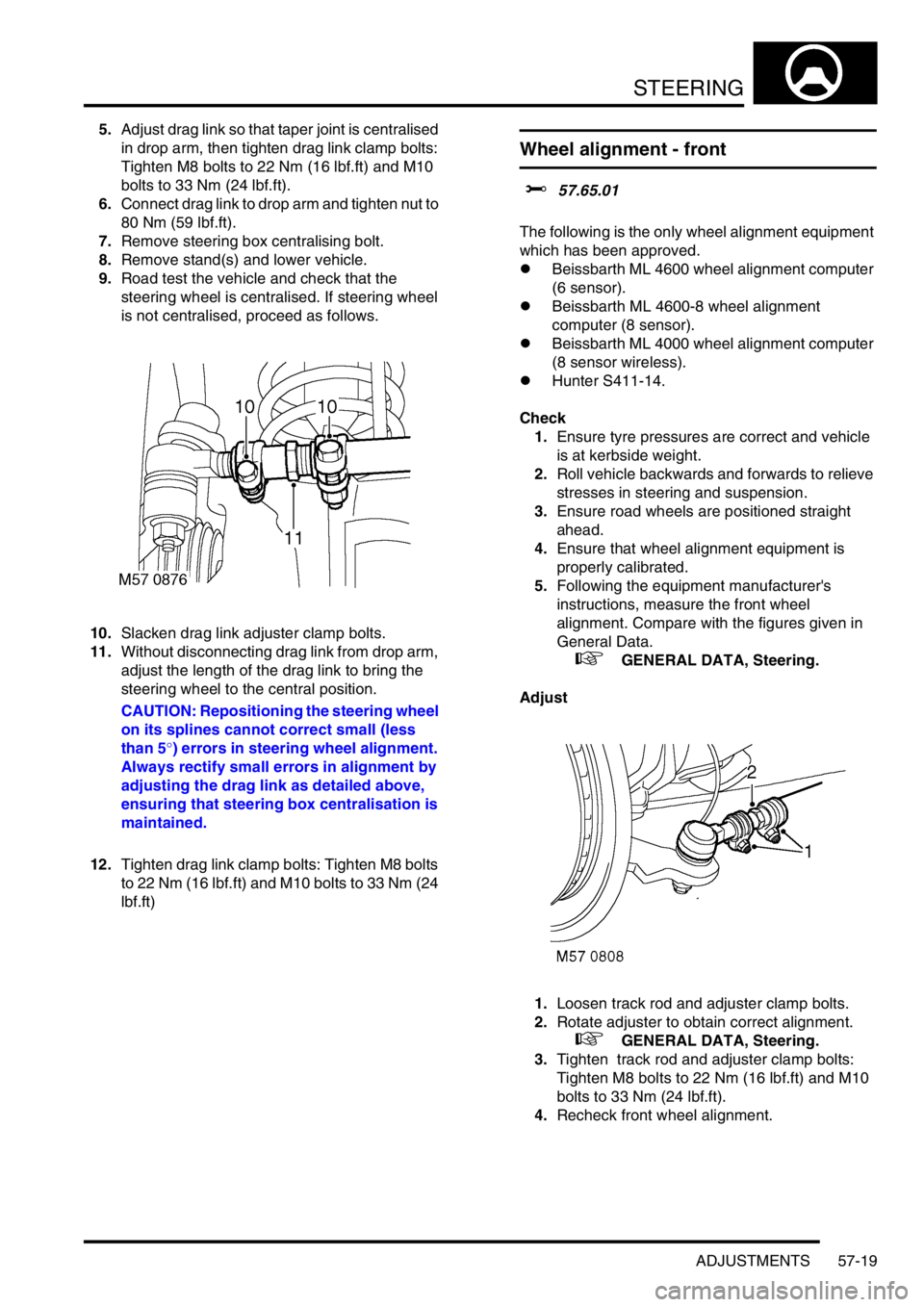
5.Adjust drag link so that taper joint is centralised
in drop arm, then tighten drag link clamp bolts:
Tighten M8 bolts to 22 Nm (16 lbf.ft) and M10
bolts to 33 Nm (24 lbf.ft).
6.Connect drag link to drop arm and tighten nut to
80 Nm (59 lbf.ft).
7.Remove steering box centralising bolt.
8.Remove stand(s) and lower vehicle.
9.Road test the vehicle and check that the
steering wheel is centralised. If steering wheel
is not centralised, proceed as follows.
10.Slacken drag link adjuster clamp bolts.
11.Without disconnecting drag link from drop arm,
adjust the length of the drag link to bring the
steering wheel to the central position.
CAUTION: Repositioning the steering wheel
on its splines cannot correct small (less
than 5°) errors in steering wheel alignment.
Always rectify small errors in alignment by
adjusting the drag link as detailed above,
ensuring that steering box centralisation is
maintained.
12.Tighten drag link clamp bolts: Tighten M8 bolts
to 22 Nm (16 lbf.ft) and M10 bolts to 33 Nm (24
lbf.ft)
Wheel alignment - front
$% 57.65.01
The following is the only wheel alignment equipment
which has been approved.
lBeissbarth ML 4600 wheel alignment computer
(6 sensor).
lBeissbarth ML 4600-8 wheel alignment
computer (8 sensor).
lBeissbarth ML 4000 wheel alignment computer
(8 sensor wireless).
lHunter S411-14.
Check
1.Ensure tyre pressures are correct and vehicle
is at kerbside weight.
2.Roll vehicle backwards and forwards to relieve
stresses in steering and suspension.
3.Ensure road wheels are positioned straight
ahead.
4.Ensure that wheel alignment equipment is
properly calibrated.
5.Following the equipment manufacturer's
instructions, measure the front wheel
alignment. Compare with the figures given in
General Data.
+ GENERAL DATA, Steering.
Adjust
1.Loosen track rod and adjuster clamp bolts.
2.Rotate adjuster to obtain correct alignment.
+ GENERAL DATA, Steering.
3.Tighten track rod and adjuster clamp bolts:
Tighten M8 bolts to 22 Nm (16 lbf.ft) and M10
bolts to 33 Nm (24 lbf.ft).
4.Recheck front wheel alignment.
Page 713 of 1529
STEERING
57-20 ADJUSTMENTS
Power steering pressure check - diesel
models
$% 57.90.10.01
Check
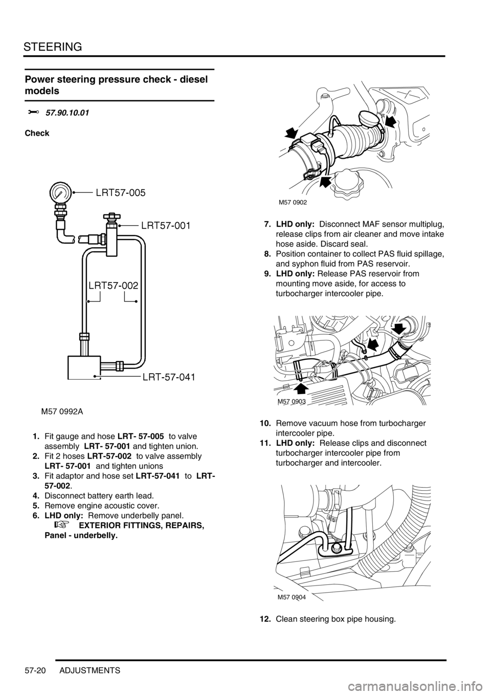
1.Fit gauge and hose LRT- 57-005 to valve
assembly LRT- 57-001 and tighten union.
2.Fit 2 hoses LRT-57-002 to valve assembly
LRT- 57-001 and tighten unions
3.Fit adaptor and hose set LRT-57-041 to LRT-
57-002.
4.Disconnect battery earth lead.
5.Remove engine acoustic cover.
6. LHD only: Remove underbelly panel.
+ EXTERIOR FITTINGS, REPAIRS,
Panel - underbelly.7. LHD only: Disconnect MAF sensor multiplug,
release clips from air cleaner and move intake
hose aside. Discard seal.
8.Position container to collect PAS fluid spillage,
and syphon fluid from PAS reservoir.
9. LHD only: Release PAS reservoir from
mounting move aside, for access to
turbocharger intercooler pipe.
10.Remove vacuum hose from turbocharger
intercooler pipe.
11. LHD only: Release clips and disconnect
turbocharger intercooler pipe from
turbocharger and intercooler.
12.Clean steering box pipe housing.
M57 0902
M57 0903
M57 0904
Page 714 of 1529
STEERING
ADJUSTMENTS 57-21
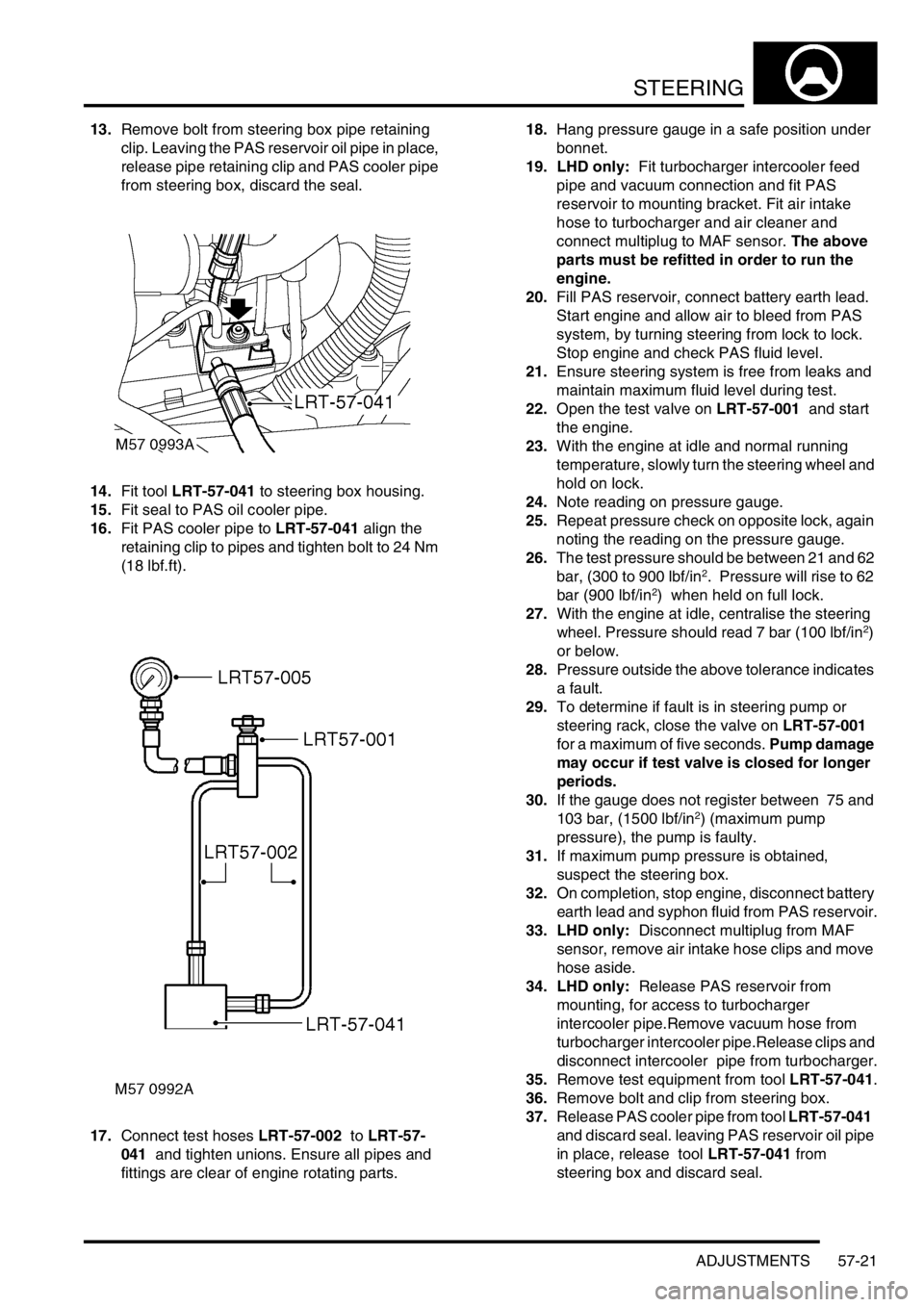
13.Remove bolt from steering box pipe retaining
clip. Leaving the PAS reservoir oil pipe in place,
release pipe retaining clip and PAS cooler pipe
from steering box, discard the seal.
14.Fit tool LRT-57-041 to steering box housing.
15.Fit seal to PAS oil cooler pipe.
16.Fit PAS cooler pipe to LRT-57-041 align the
retaining clip to pipes and tighten bolt to 24 Nm
(18 lbf.ft).
17.Connect test hoses LRT-57-002 to LRT-57-
041 and tighten unions. Ensure all pipes and
fittings are clear of engine rotating parts.18.Hang pressure gauge in a safe position under
bonnet.
19. LHD only: Fit turbocharger intercooler feed
pipe and vacuum connection and fit PAS
reservoir to mounting bracket. Fit air intake
hose to turbocharger and air cleaner and
connect multiplug to MAF sensor. The above
parts must be refitted in order to run the
engine.
20.Fill PAS reservoir, connect battery earth lead.
Start engine and allow air to bleed from PAS
system, by turning steering from lock to lock.
Stop engine and check PAS fluid level.
21.Ensure steering system is free from leaks and
maintain maximum fluid level during test.
22.Open the test valve on LRT-57-001 and start
the engine.
23.With the engine at idle and normal running
temperature, slowly turn the steering wheel and
hold on lock.
24.Note reading on pressure gauge.
25.Repeat pressure check on opposite lock, again
noting the reading on the pressure gauge.
26.The test pressure should be between 21 and 62
bar, (300 to 900 lbf/in
2. Pressure will rise to 62
bar (900 lbf/in2) when held on full lock.
27.With the engine at idle, centralise the steering
wheel. Pressure should read 7 bar (100 lbf/in
2)
or below.
28.Pressure outside the above tolerance indicates
a fault.
29.To determine if fault is in steering pump or
steering rack, close the valve on LRT-57-001
for a maximum of five seconds. Pump damage
may occur if test valve is closed for longer
periods.
30.If the gauge does not register between 75 and
103 bar, (1500 lbf/in
2) (maximum pump
pressure), the pump is faulty.
31.If maximum pump pressure is obtained,
suspect the steering box.
32.On completion, stop engine, disconnect battery
earth lead and syphon fluid from PAS reservoir.
33. LHD only: Disconnect multiplug from MAF
sensor, remove air intake hose clips and move
hose aside.
34. LHD only: Release PAS reservoir from
mounting, for access to turbocharger
intercooler pipe.Remove vacuum hose from
turbocharger intercooler pipe.Release clips and
disconnect intercooler pipe from turbocharger.
35.Remove test equipment from tool LRT-57-041.
36.Remove bolt and clip from steering box.
37.Release PAS cooler pipe from tool LRT-57-041
and discard seal. leaving PAS reservoir oil pipe
in place, release tool LRT-57-041 from
steering box and discard seal.