LAND ROVER DISCOVERY 2002 Workshop Manual
Manufacturer: LAND ROVER, Model Year: 2002, Model line: DISCOVERY, Model: LAND ROVER DISCOVERY 2002Pages: 1672, PDF Size: 46.1 MB
Page 1001 of 1672

FRONT SUSPENSION
60-62 REPAIRS
4.Remove 2 nuts securing rear anti-roll bar links
to axle.
5.Release links from axle and pull long arm down
for access to actuator pipe unions.
6.Position container under actuator to collect
fluid spillage.
7.Remove 2 cap nuts securing pipes to ACE rear
actuator. Disconnect pipes, remove and
discard sealing washers.
CAUTION: Always fit plugs to open
connections to prevent contamination.
8.Remove 2 nuts securing rear pipe clamping
plate. Release clamping plate and pipes from
valve block.
CAUTION: Always fit plugs to open
connections to prevent contamination.
9.Remove pipe assembly.
10.Remove collets and clamping plate from rear
pipes. Refit
1.Ensure valve block and pipe connections are
clean.
2.Install clamping plate and collets on rear pipes.
3.Position pipe assembly to vehicle and connect
pipes and clamping plate to valve block. To
avoid damage to seals, keep pipes square
to valve block. Fit and tighten nuts securing
clamping plate to valve block to 21 Nm (15
lbf.ft).
CAUTION: Ensure pipes are installed in
their correct ports or serious system
damage will occur.
4.Fit bolts securing rear pipe clips to chassis and
tighten to 6 Nm (4.4 lbf.ft).
5.Connect pipes to actuator with cap nuts and
new sealing washers. Tighten cap nuts to 29
Nm (21 lbf.ft). Ensure pipes are not under
tension or kinked.
6.Ensure washer is in place on lower ball joint of
each anti-roll bar link, then connect lower ball
joints to axle and tighten nuts to 100 Nm (74
lbf.ft).
7.Renew ACE high pressure filter.
+ FRONT SUSPENSION, REPAIRS,
Filter - high pressure - ACE.
8.Bleed ACE hydraulic system.
+ FRONT SUSPENSION,
ADJUSTMENTS, ACE hydraulic system
bleeding.
9.Lower vehicle.
Page 1002 of 1672

FRONT SUSPENSION
REPAIRS 60-63
Actuator - front - ACE
$% 60.60.40
CAUTION: The ACE hydraulic system is
extremely sensitive to the ingress of dirt or
debris. The smallest amount could render the
system unserviceable. It is imperative that the
following precautions are taken.
lACE components are thoroughly cleaned
externally before work commences;
lall opened pipe and module ports are
capped immediately;
lall fluid is stored in and administered
through clean containers.
Remove
1.Raise vehicle on a ramp.
2.Remove RH front road wheel.
3.Position container to collect fluid spillage.
4.Remove cap nuts securing fluid pipes to
actuator. Disconnect pipes and discard sealing
washers.
CAUTION: Always fit plugs to open
connections to prevent contamination.5.Remove 2 nuts securing anti-roll bar links to
axle. Release links from axle.
6.With assistance, remove 2 bolts and remove
both clamp plates from torsion bar.
7.Remove mounting rubbers from torsion bar.
8.Remove torsion bar and actuator assembly.
CAUTION: While removed from the vehicle,
ensure torsion bar is stored without any
load on the anti-roll bar links, or the ball
joints and/or link rods could be damaged.
Page 1003 of 1672

FRONT SUSPENSION
60-64 REPAIRS
9.Use LRT-60-009 to remove nut securing
actuator to long arm.
10.Remove nut and bolt securing actuator to short
arm and remove actuator.
CAUTION: The short arm and torsion bar
are supplied as an assembly and must not
be separated.Refit
1.Fit actuator to torsion bar. Use LRT-60-009to
tighten actuator to long arm nut to 48 Nm (35
lbf.ft). Tighten actuator to short arm nut and bolt
to 180 Nm (133 lbf.ft).
2.Ensure torsion bar mounting rubber mating
faces are clean and free from damage.
3.Fit mounting rubbers to torsion bar.
4.With assistance, position torsion bar and
actuator assembly to vehicle. Fit clamp plates
and tighten bolts to 45 Nm (33 lbf.ft).
5.Ensure washer is in place on lower ball joint of
each anti-roll bar link, then connect lower ball
joint to axle and tighten nuts to 100 Nm (74
lbf.ft).
6.Connect pipes to actuator with cap nuts and
new sealing washers. Tighten cap nuts to 29
Nm (21 lbf.ft). Ensure pipes are not under
tension or kinked.
7.Renew ACE high pressure filter.
+ FRONT SUSPENSION, REPAIRS,
Filter - high pressure - ACE.
8.Bleed ACE hydraulic system.
+ FRONT SUSPENSION,
ADJUSTMENTS, ACE hydraulic system
bleeding.
9.Fit RH front road wheel and tighten nuts to 140
Nm (103 lbf.ft).
10.Lower vehicle.
Page 1004 of 1672

FRONT SUSPENSION
REPAIRS 60-65
Bushes - front long arm - ACE
$% 60.60.46
Remove
1.Remove ACE front actuator.
+ FRONT SUSPENSION, REPAIRS,
Actuator - front - ACE.
2.Remove securing nut and remove anti-roll bar
link from torsion bar.
3.Restrain torsion bar and remove long arm
securing bolt and washer. Remove long arm
from torsion bar.
CAUTION: The short arm and torsion bar
are supplied as an assembly and must not
be separated.
4.Use a suitable drift to remove both halves of
slipper bush from long arm.
5.Use suitable adaptors to press actuator rod end
bush from long arm.Refit
1.Clean bush locations in long arm.
2.Use suitable adaptors to press new actuator
rod end bush into long arm. Ensure hole in bush
is correctly aligned with hole in long arm.
3.Align slots in new slipper bush halves with
those in long arm. Carefully press both halves
of slipper bush into long arm. Ensure the
sealing rings on the slipper bush faces are not
damaged.
Page 1005 of 1672

FRONT SUSPENSION
60-66 REPAIRS
4.Clean long arm and mating face on torsion bar.
5.Fit long arm to torsion bar. Restrain torsion bar
and tighten bolt to 180 Nm (133 lbf.ft).
6.Fit anti-roll bar link to long arm and tighten nut
to 50 Nm (37 lbf.ft).
7.Fit ACE front actuator.
+ FRONT SUSPENSION, REPAIRS,
Actuator - front - ACE.
Page 1006 of 1672

REAR SUSPENSION
DESCRIPTION AND OPERATION 64-1
Deze pagina werd opzettelijk niet gebruikt
Cette page est intentionnellement vierge
Questa pagina è stata lasciata in bianco di proposito Diese Seite ist leer
Esta página foi deixada intencionalmente em branco
Esta página fue dejada en blanco intencionalmente This page is intentionally left blank
REAR SUSPENSION DESCRIPTION AND OPERAT ION
Page 1007 of 1672

REAR SUSPENSION
64-2 DESCRIPTION AND OPERATION
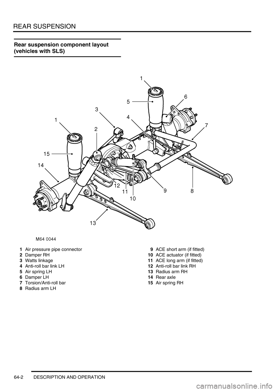
Rear suspension component layout
(vehicles with SLS)
1Air pressure pipe connector
2Damper RH
3Watts linkage
4Anti-roll bar link LH
5Air spring LH
6Damper LH
7Torsion/Anti-roll bar
8Radius arm LH9ACE short arm (if fitted)
10ACE actuator (if fitted)
11ACE long arm (if fitted)
12Anti-roll bar link RH
13Radius arm RH
14Rear axle
15Air spring RH
Page 1008 of 1672

REAR SUSPENSION
DESCRIPTION AND OPERATION 64-3
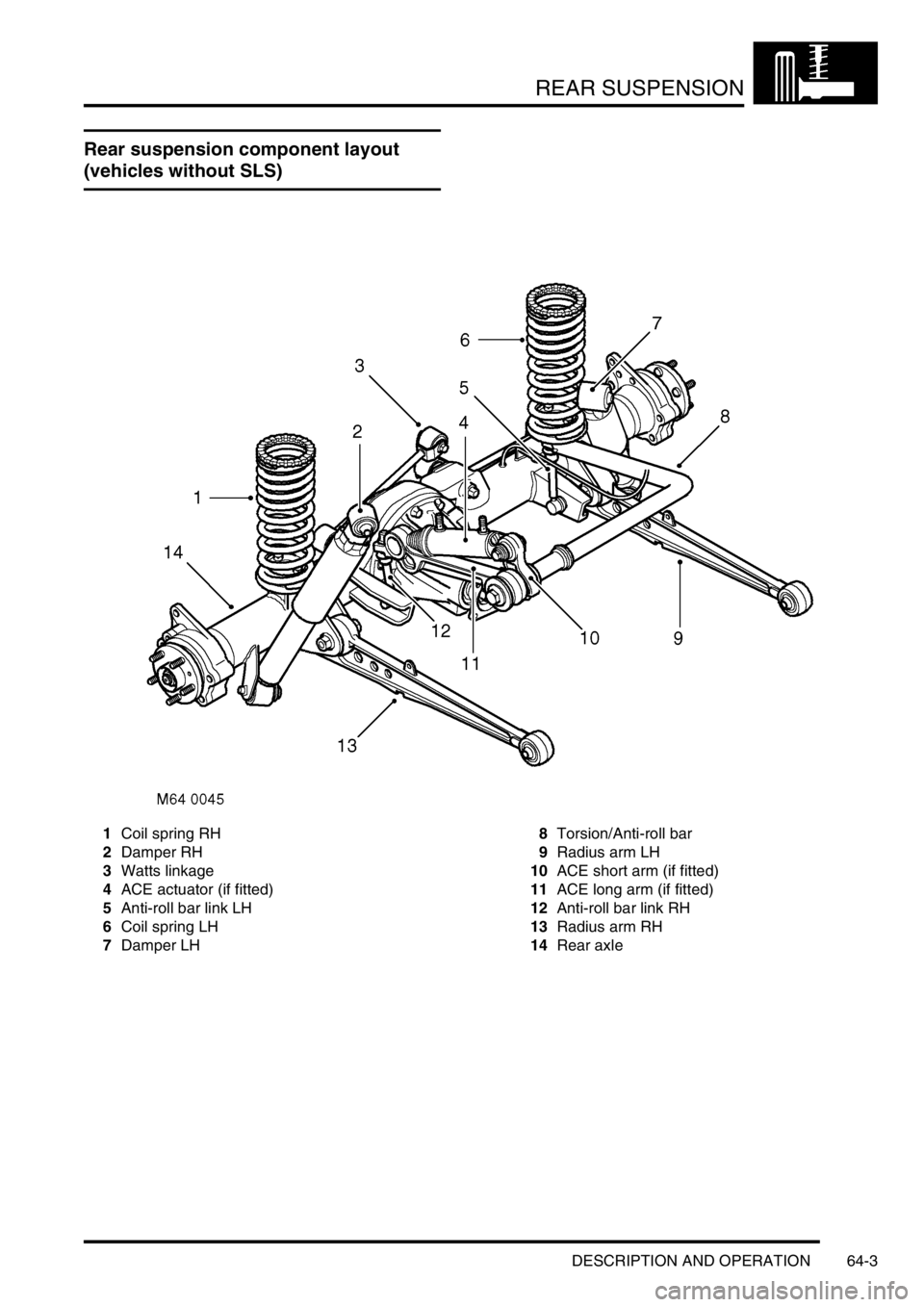
Rear suspension component layout
(vehicles without SLS)
1Coil spring RH
2Damper RH
3Watts linkage
4ACE actuator (if fitted)
5Anti-roll bar link LH
6Coil spring LH
7Damper LH8Torsion/Anti-roll bar
9Radius arm LH
10ACE short arm (if fitted)
11ACE long arm (if fitted)
12Anti-roll bar link RH
13Radius arm RH
14Rear axle
Page 1009 of 1672

REAR SUSPENSION
64-4 DESCRIPTION AND OPERATION
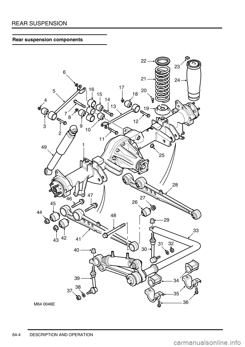
Rear suspension components
47
44
45
40
3738
39
36
35
34
33
32
23
19
18
1716
M64 0046E
1
2
3
4
5
6
78
910
11
12
13
14
1520
21
22
24
25
26
27
28
29
30
414243
46
48
49
31
Page 1010 of 1672

REAR SUSPENSION
DESCRIPTION AND OPERATION 64-5
1Rear axle
2Bolt
3Bush
4Locknut
5Transverse link
6Locknut
7Bolt
8Locknut
9Bush
10Bush
11Bolt
12Bolt
13Transverse link
14Bolt
15Bush
16Pivot housing
17Locknut
18Bush
19Lower spring seat 2 off (vehicles without SLS
only)
20Bolt 4 off (vehicles without SLS only)
21Coil spring 2 off (vehicles without SLS only)
22Spring seat isolator 2 off (vehicles without SLS
only)
23Clip 4 off (vehicles with SLS only)
24Air spring 2 off (vehicles with SLS only)
25Locknut
26Bush 2 off27Locknut 2 off
28Radius arm LH
29Locknut
30Torsion/Anti-roll bar link LH
31Washer
32Locknut
33Anti-roll bar assembly
34Mounting rubber 2 off
35Clamp plate 2 off
36Bolt 2 off
37Locknut
38Washer
39Anti-roll bar link RH
40Locknut
41Radius arm RH
42Bush 2 off
43Locknut 2 off
44Locknut 2 off
45Bush 2 off
46Bolt 2 off
47Bolt 2 off
48Bolt 2 off
49Damper 2 off