ECU LAND ROVER DISCOVERY 2002 Workshop Manual
[x] Cancel search | Manufacturer: LAND ROVER, Model Year: 2002, Model line: DISCOVERY, Model: LAND ROVER DISCOVERY 2002Pages: 1672, PDF Size: 46.1 MB
Page 315 of 1672
ENGINE - V8
12-2-72 OVERHAUL
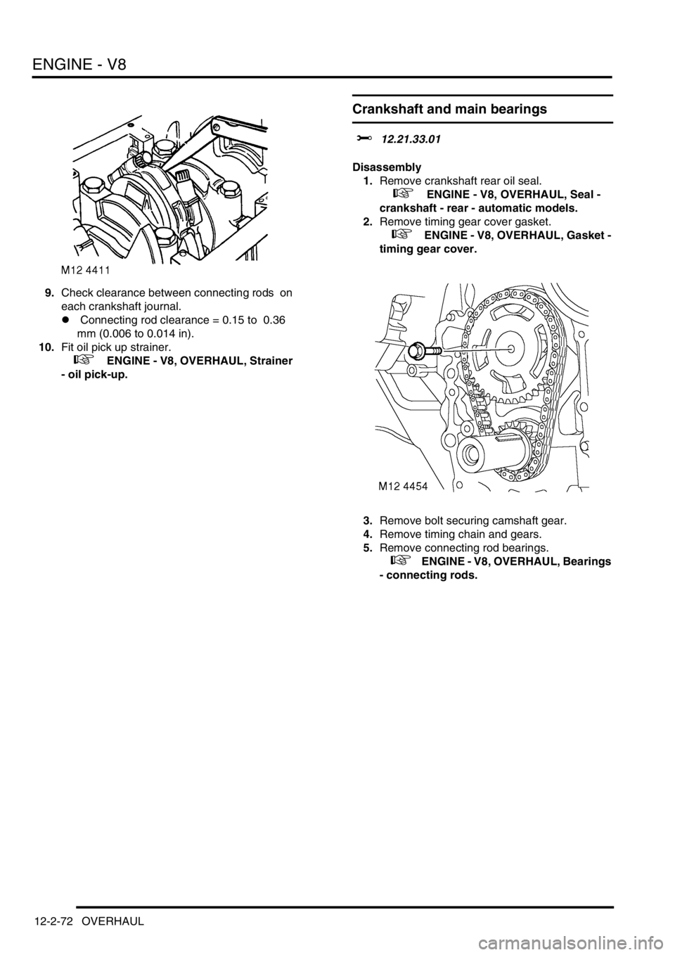
9.Check clearance between connecting rods on
each crankshaft journal.
l Connecting rod clearance = 0.15 to 0.36
mm (0.006 to 0.014 in).
10.Fit oil pick up strainer.
+ ENGINE - V8, OVERHAUL, Strainer
- oil pick-up.
Crankshaft and main bearings
$% 12.21.33.01
Disassembly
1.Remove crankshaft rear oil seal.
+ ENGINE - V8, OVERHAUL, Seal -
crankshaft - rear - automatic models.
2.Remove timing gear cover gasket.
+ ENGINE - V8, OVERHAUL, Gasket -
timing gear cover.
3.Remove bolt securing camshaft gear.
4.Remove timing chain and gears.
5.Remove connecting rod bearings.
+ ENGINE - V8, OVERHAUL, Bearings
- connecting rods.
Page 316 of 1672
ENGINE - V8
OVERHAUL 12-2-73
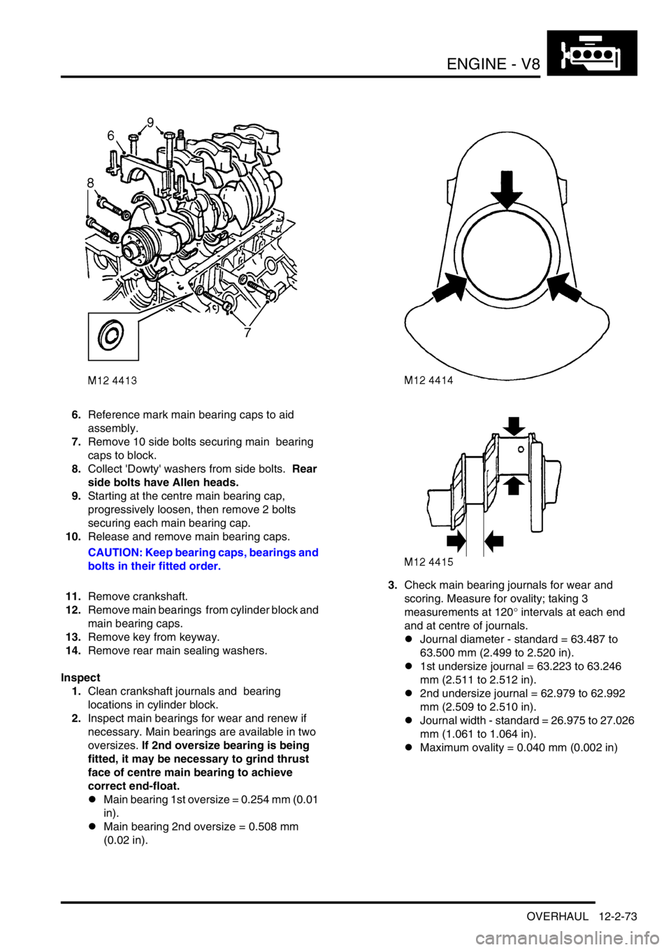
6.Reference mark main bearing caps to aid
assembly.
7.Remove 10 side bolts securing main bearing
caps to block.
8.Collect 'Dowty' washers from side bolts. Rear
side bolts have Allen heads.
9.Starting at the centre main bearing cap,
progressively loosen, then remove 2 bolts
securing each main bearing cap.
10.Release and remove main bearing caps.
CAUTION: Keep bearing caps, bearings and
bolts in their fitted order.
11.Remove crankshaft.
12.Remove main bearings from cylinder block and
main bearing caps.
13.Remove key from keyway.
14.Remove rear main sealing washers.
Inspect
1.Clean crankshaft journals and bearing
locations in cylinder block.
2.Inspect main bearings for wear and renew if
necessary. Main bearings are available in two
oversizes. If 2nd oversize bearing is being
fitted, it may be necessary to grind thrust
face of centre main bearing to achieve
correct end-float.
lMain bearing 1st oversize = 0.254 mm (0.01
in).
lMain bearing 2nd oversize = 0.508 mm
(0.02 in).3.Check main bearing journals for wear and
scoring. Measure for ovality; taking 3
measurements at 120
° intervals at each end
and at centre of journals.
lJournal diameter - standard = 63.487 to
63.500 mm (2.499 to 2.520 in).
l1st undersize journal = 63.223 to 63.246
mm (2.511 to 2.512 in).
l2nd undersize journal = 62.979 to 62.992
mm (2.509 to 2.510 in).
lJournal width - standard = 26.975 to 27.026
mm (1.061 to 1.064 in).
lMaximum ovality = 0.040 mm (0.002 in)
Page 319 of 1672
ENGINE - V8
12-2-76 OVERHAUL
Camshaft
$% 12.13.02.01
Disassembly
1.Remove inlet manifold gasket.
+ ENGINE - V8, OVERHAUL, Gasket -
inlet manifold.
2.Progressively loosen and remove 8 bolts
securing rocker shaft assemblies.
3.Mark each rocker shaft in relation to original
head.
4.Remove rocker shaft assemblies.
5.Remove push rods and store in their fitted
order.
6.Remove tappets.
7.Remove timing chain and gears.
+ ENGINE - V8, OVERHAUL, Timing
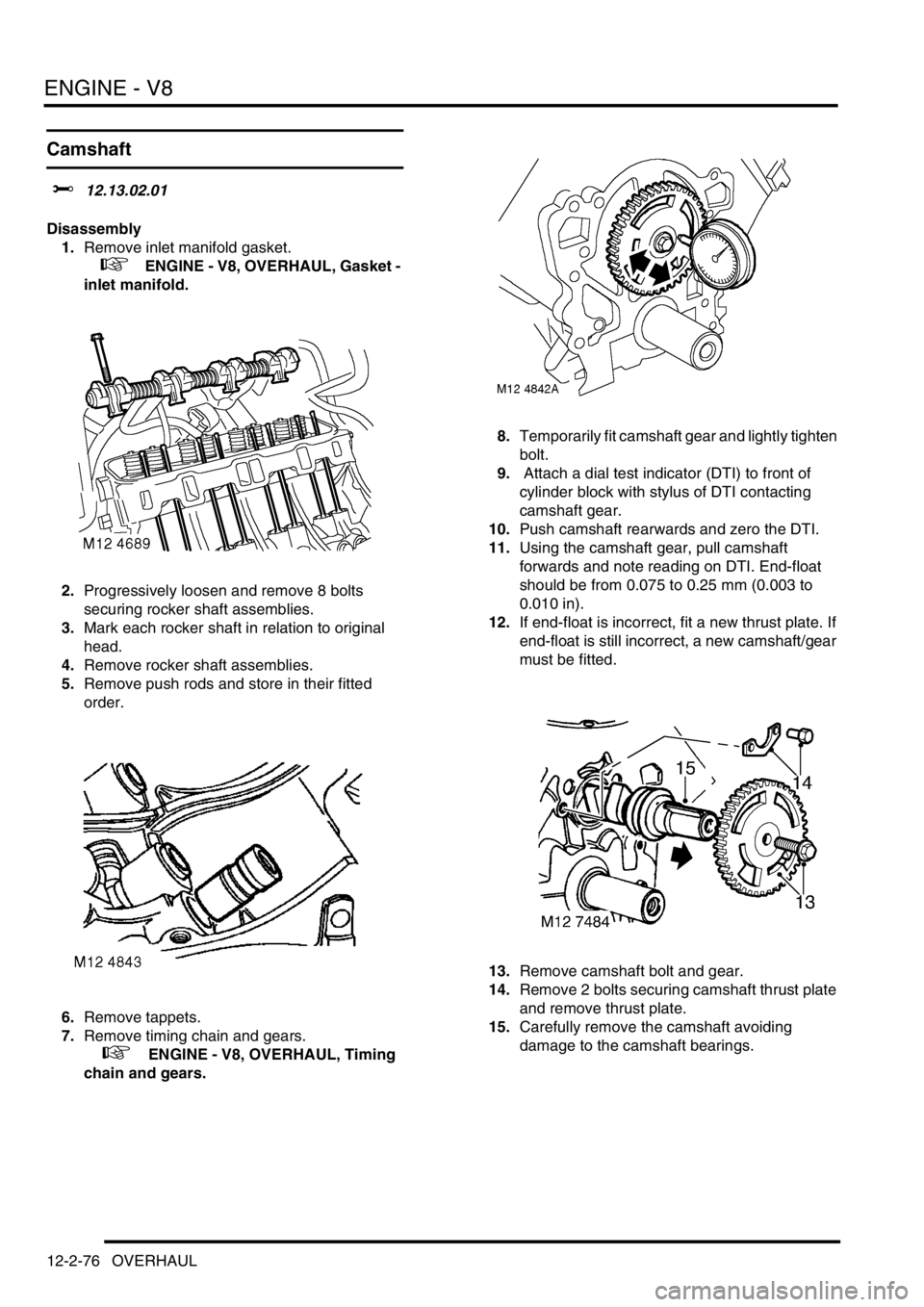
chain and gears.8.Temporarily fit camshaft gear and lightly tighten
bolt.
9. Attach a dial test indicator (DTI) to front of
cylinder block with stylus of DTI contacting
camshaft gear.
10.Push camshaft rearwards and zero the DTI.
11.Using the camshaft gear, pull camshaft
forwards and note reading on DTI. End-float
should be from 0.075 to 0.25 mm (0.003 to
0.010 in).
12.If end-float is incorrect, fit a new thrust plate. If
end-float is still incorrect, a new camshaft/gear
must be fitted.
13.Remove camshaft bolt and gear.
14.Remove 2 bolts securing camshaft thrust plate
and remove thrust plate.
15.Carefully remove the camshaft avoiding
damage to the camshaft bearings.
Page 327 of 1672
EMISSION CONTROL - TD5
17-1-6 DESCRIPTION AND OPERATION
The EGR modulator is located on a plate fixed to the inner wing on the RH side of the engine. The modulator is
attached to the plate by two through-studs, each with two nuts which secure the modulator assembly to a rubber
mounting which helps to reduce noise. The modulator must be mounted in the vertical orientation with the two vacuum
ports uppermost.
The modulator operation is controlled by a signal from the ECM which determines the required amount of EGR
needed in response to inputs relating to air flow and engine operating and ambient conditions. The modulator has a
black two-pin connector at its base to connect it to the ECM through the engine harness.
Each modulator features three ports:
lThe top port of the EGR modulator is identified by a white band and connects to a 'T'-piece in the vacuum line
via a small-bore brown plastic hose. On type 2 systems the brown hose is connected in parallel with the vacuum
source to the ILT modulator.
The other two ports on the 'T'-piece connects vacuum line hoses of black vinyl tubing between the vacuum pump
and the brake-servo assembly attached to the bulkhead. The vacuum pump end of the vacuum line tubing
terminates in a rubber elbow, which gives a vacuum tight seal on the suction port of the vacuum pump. The
brake-servo end of the vacuum line tubing terminates with a non-return valve in a plastic housing which plugs
into the front face of the brake-servo housing.
lThe middle port of the EGR modulator is identified by a blue band and connects to the suction port on the EGR
valve through a small-bore blue plastic hose.
lThe lower port of the EGR modulator is identified by a green band and connects to atmosphere through an in-
line filter via a small-bore green plastic hose. On type 2 models a 3 way connector is fitted to vent both modulators
through a single filter. The other port of the in-line filter vents directly to atmosphere.
The blue and brown vacuum hoses are protected by corrugated plastic sheaths. The ends of the hoses are fitted with
rubber boots to ensure vacuum tight seals at the component ports.
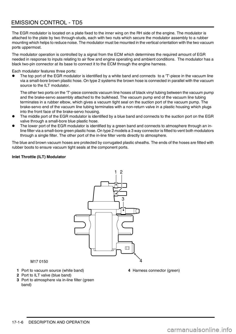
Inlet Throttle (ILT) Modulator
1Port to vacuum source (white band)
2Port to ILT valve (blue band)
3Port to atmosphere via in-line filter (green
band)4Harness connector (green)
Page 328 of 1672
EMISSION CONTROL - TD5
DESCRIPTION AND OPERATION 17-1-7
The ILT modulator is located on a plate fixed to the inner wing on the RH side of the engine below the EGR modulator.
The modulator is attached to the plate by two through-studs, each with two nuts which secure the modulator assembly
to a rubber mounting which helps to reduce noise. The modulator must be mounted in the vertical orientation with the
two vacuum ports uppermost.
The modulator operation is controlled by a signal from the ECM which determines the required ratio of exhaust gas
to fresh inlet air needed in response to inputs relating to air flow and engine operating and ambient conditions. The
modulator has a green two-pin connector at its base to connect it to the ECM through the engine harness.
The ILT valve modulator features three ports:
lThe top port is identified by a white band and connects to a 'T'-piece in the vacuum line via a small-bore brown
plastic hose where it is connected in parallel with the vacuum source line to the EGR valve modulator. The two
other ports on the 'T'-piece connect vacuum line hoses of black vinyl tubing between the vacuum pump attached
to the alternator and the brake-servo assembly attached to the bulkhead.
lThe middle port is identified by a blue band and connects to the suction port on the ILT valve through a small-
bore blue plastic hose.
lThe lower port is identified by a green band and connects to atmosphere through an in-line filter via a green
plastic hose and a three-way connector positioned in-line between the modulators and the filter. The ILT
modulator hose is connected opposite to the two parallel ports at the three-way connector which connect the vent
lines to the EGR valve modulator and the in-line filter. The other port of the in-line filter vents directly to
atmosphere.
The blue and brown vacuum hoses are protected by corrugated plastic sheaths. The ends of the hoses are fitted with
rubber boots to ensure vacuum tight seals at the component ports.
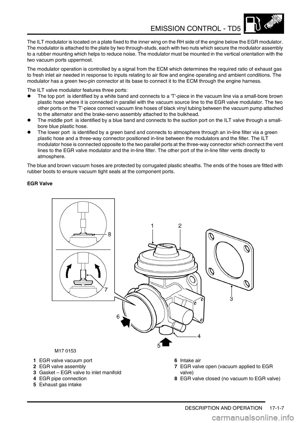
EGR Valve
1EGR valve vacuum port
2EGR valve assembly
3Gasket – EGR valve to inlet manifold
4EGR pipe connection
5Exhaust gas intake6Intake air
7EGR valve open (vacuum applied to EGR
valve)
8EGR valve closed (no vacuum to EGR valve)
Page 331 of 1672

EMISSION CONTROL - TD5
17-1-10 DESCRIPTION AND OPERATION
EGR systems
There are two types of exhaust gas recirculation system used with the Td5 engine dependent on legislation and
market requirements, these are type 1 and type 2.
Type 1 EGR system is fitted to all Td5's built up to the introduction of 2002 MY, except for Japanese specification
vehicles.
Type 2 EGR system is fitted to all Japanese specification vehicles and was introduced into European markets for 2002
MY to meet EU3 emission requirements. An additional feature introduced at 2002 MY is the EGR cooler, which is
bolted to the front of the cylinder head.
EGR system - type 1
This EGR system features a single modulator which is electrically controlled to modulate a vacuum source to the EGR
valve. The controlled vacuum opens and closes the valve by the amount required to ensure the optimal proportion of
exhaust gas is allowed through to the inlet manifold to be combined with the fresh air intake. Control feedback is
achieved by monitoring the mass of fresh air flowing through the mass air flow sensor.
The modulator operation is controlled by a signal from the ECM which determines the required amount of EGR
needed in response to inputs relating to air flow and engine operating and ambient conditions. The ECM is low-side
driven, sinking current returned from the vacuum modulator for switching operating condition.
The exhaust gases are routed from the exhaust manifold through a shaped metal pipe which connects to the
underside of the EGR valve. The pipe is held securely in position to the front of the cylinder head using a clamp
bracket. The EGR pipe is attached to a mating port at the front end of the exhaust manifold using two Allen screws
and at the EGR valve assembly by a metal band clamp. The two Allen screws fixing the EGR pipe to the exhaust
manifold should be replaced every time the EGR pipe is removed. Extreme care should be exercised when
removing and refitting the EGR pipe to avoid damage.
When a vacuum is applied to the EGR suction port, it causes a spindle with sealing disc (EGR valve) to be raised,
thus opening the port at the EGR pipe to allow the recirculated exhaust gas to pass through into the inlet manifold.
The valve is spring loaded so that when the vacuum is removed from the suction port the valve returns to its rest
position to tightly close the exhaust gas port.
By controlling the quantity of recirculated exhaust gas available in the inlet manifold, the optimum mix for the prevailing
engine operating conditions can be maintained, which ensures the intake gas to the combustion chambers will have
burning rate properties which will reduce the NO
x emissions to an acceptable level. Normally, full recirculation is only
applicable when the NO
x emissions are most prevalent.
EGR system - type 2
This system features twin modulators mounted one above the other on a metal plate located on the inner wing at the
RH side of the engine. The modulators are electrically controlled by the engine management system and are used to
modulate a vacuum source to the EGR valve and a supplementary Inlet Throttle (ILT) valve; the two valves are
controlled to operate in tandem. The ILT valve vacuum pot is mounted adjacent to the EGR valve housing and has a
linkage which connects to a butterfly valve mounted in front of the EGR valve at the air intake manifold.
The modulator operations are electrically controlled by signals from the engine management system which
determines the required volume of exhaust gas needed in response to inputs relating to air flow, engine operating
conditions and ambient parameters such as temperature and altitude. The engine management ECM switches on the
circuit by completing the path to ground, operating the vacuum modulators.
Pre EU3 models: The exhaust gases are routed from the exhaust manifold through a shaped metal pipe which
connects to the underside of the EGR valve. The pipe is held securely in position to the front of the engine cylinder
head using a metal clamp bracket. The EGR pipe is attached to a mating port at the front end of the exhaust manifold
using two Allen screws and at the EGR valve assembly by a metal band clamp. The two Allen screws fixing the EGR
pipe to the exhaust manifold should be replaced every time the EGR pipe is removed. Extreme care should be
exercised when removing and refitting the EGR pipe to avoid damage.
Page 332 of 1672

EMISSION CONTROL - TD5
DESCRIPTION AND OPERATION 17-1-11
EU3 models: The exhaust gases are routed from the exhaust manifold through the EGR cooler to the underside of
the EGR valve. The EGR cooler is bolted to the front of the engine cylinder head. An EGR pipe connects the EGR
cooler to the exhaust manifold and is secured by two Allen screws. The two Allen screws fixing the EGR pipe to the
exhaust manifold should be replaced every time the EGR pipe is removed. A second pipe connects the EGR cooler
to the EGR valve; this pipe is secured to the EGR valve by a clip, and to the cooler by two Allen screws.Extreme care
should be exercised when removing and refitting the EGR pipe to avoid damage. When refitting the EGR
cooler, always tighten the pipe connections BEFORE tightening the bolts securing the cooler to the cylinder
head.
When a vacuum is applied to the EGR suction port, it causes a spindle with sealing disc (EGR valve) to be raised,
opening the port at the EGR pipe to allow the recirculated exhaust gas to pass through into the inlet manifold. The
valve is spring loaded so that when the vacuum is removed from the suction port, the valve returns to its rest position
to tightly close the exhaust gas port.
A vacuum is simultaneously applied to the inlet throttle (ILT) valve suction port which causes the butterfly valve in the
inlet manifold to close by means of a spindle and lever mechanism. Closing the butterfly valve limits the supply of
fresh intercooled air entering the inlet manifold and causes a depression within the inlet manifold to create a greater
suction at the open port to the EGR delivery pipe. In this condition a greater mass of recirculated exhaust gas is drawn
into the inlet manifold for use in the combustion process. When the vacuum is released from the ILT valve suction port
a spring returns the butterfly valve to its fully open position.
By controlling the quantities of recirculated exhaust gas and fresh intake air available in the inlet manifold, the
optimum mix for the prevailing engine operating conditions can be maintained which ensures the intake gas to the
combustion chambers will have burning rate properties which will reduce the NO
x emissions to an acceptable level.
Normally, full recirculation is only applicable when the NO
x emissions are most prevalent.
Page 334 of 1672

EMISSION CONTROL - TD5
REPAIRS 17-1-13
REPAIRS
Modulator - EGR
$% 17.45.04
There are two types of modulator fitted. System type
1 has a single modulator, and type 2 has a second
modulator (ILT modulator) bolted to the same
mounting plate.
Remove
1.Disconnect vacuum pipe(s) and multiplug(s)
from EGR modulator.
2.Remove 2 nuts and remove EGR modulator.
Refit
1.Position EGR modulator and tighten securing
nuts.
2.Connect vacuum hose(s) and multiplug(s).
Inlet Throttle (ILT) Modulator
$% 17.45.03
Remove
1.Identify the fitted positions of the 3 vacuum
pipes, then disconnect from the ILT modulator
valve.
2.Disconnect multiplug from ILT modulator.
3.Remove 2 nuts securing modulator and remove
ILT modulator from its mountings.
Refit
1.Fit ILT modulator to its mountings, fit the nuts
and tighten to 10 Nm (7 lbf.ft).
2.Connect vacuum pipes to the positions
identified during removal.
3.Connect multiplug to ILT modulator.
Page 335 of 1672

EMISSION CONTROL - TD5
17-1-14 REPAIRS
Valve - EGR - Pre EU3 models
$% 17.45.01
On all vehicles up to VIN number 1A736339, the
EGR pipe assembly must be replaced every time the
system is disturbed.
Remove
1.Release turnbuckles and remove battery cover.
2.Disconnect battery earth lead.
3.Remove 3 bolts and remove engine acoustic
cover.
4.Remove cooling fan coupling.
+ COOLING SYSTEM - Td5, REPAIRS,
Fan - viscous.
5.Disconnect vacuum hose(s) from EGR valve.
6.Loosen clip and release air intake from EGR
valve.
7.Remove 4 bolts, release EGR valve from inlet
manifold and discard gasket.
8.Remove 2 bolts and release EGR valve clip
from cylinder head.
9.Remove and discard 2 bolts securing EGR
valve pipe to exhaust manifold. 10.Remove EGR valve assembly.
11.Remove clip and remove pipe from EGR valve.
Refit
1.Clean EGR valve and mating face on pipe.
2.Position pipe to EGR valve and fit retaining clip.
Fit bolt but do not tighten at this stage.
3.Position EGR valve assembly, locate pipe
flange to exhaust manifold, fit new bolts but do
not tighten at this stage.
4.Clean inlet manifold and EGR valve mating
faces.
5.Using new gasket, position EGR valve to inlet
manifold fit bolts and tighten to 10 Nm (7 lbf.ft).
6.Align EGR pipe clip to cylinder head, fit bolts
but do not tighten at this stage.
7.Tighten EGR pipe bolts to correct torque in
following sequence:
lEGR pipe retaining clip bolt 6 Nm (4.5 lbf.ft)
lEGR pipe clip to cylinder head bolts 10 Nm
(7 lbf.ft)
lEGR pipe flange to exhaust manifold bolts
10 Nm (7 lbf.ft)
8.Position air intake hose and tighten clip.
9.Connect vacuum hoses to EGR valve.
10.Fit cooling fan coupling.
+ COOLING SYSTEM - Td5, REPAIRS,
Fan - viscous.
11.Connect battery earth lead.
12.Fit battery cover and secure the fixings.
Page 336 of 1672

EMISSION CONTROL - TD5
REPAIRS 17-1-15
Valve - EGR - EU3 models
$% 17.45.01
Remove
1.Release turnbuckles and remove battery cover.
2.Disconnect battery earth lead.
3.Remove 3 bolts and remove engine acoustic
cover.
4.Remove cooling fan coupling.
+ COOLING SYSTEM - Td5, REPAIRS,
Fan - viscous.
5.Disconnect vacuum hose(s) from EGR valve.
6.Loosen clip screw and disconnect air intake
hose from EGR valve.
7.Remove screw and remove clamp securing
EGR pipe to EGR valve.
8.Remove 4 bolts securing EGR valve, remove
valve and discard gasket.
9.Discard EGR pipe gasket.Refit
1.Clean EGR valve and mating faces.
2.Fit new gasket to EGR pipe.
3.Using new gasket, position EGR valve to inlet
manifold fit bolts and tighten to 10 Nm (7 lbf.ft).
4.Fit EGR pipe clamp and tighten screw to 6 Nm
(4.4 lbf.ft).
5.Connect air intake hose to EGR valve and
tighten clip.
6.Connect vacuum hoses to EGR valve.
7.Fit cooling fan coupling.
+ COOLING SYSTEM - Td5, REPAIRS,
Fan - viscous.
8.Fit engine acoustic cover and tighten bolts to
10 Nm (7 lbf.ft).
9.Connect battery earth lead.
10.Fit battery cover and secure the fixings.