ESP LAND ROVER DISCOVERY 2002 User Guide
[x] Cancel search | Manufacturer: LAND ROVER, Model Year: 2002, Model line: DISCOVERY, Model: LAND ROVER DISCOVERY 2002Pages: 1672, PDF Size: 46.1 MB
Page 237 of 1672
ENGINE - TD5
12-1-98 OVERHAUL
Pistons, connecting rods and cylinder
bores
$% 12.17.02.03
Disassembly
1.Remove cylinder head gasket.
+ ENGINE - Td5, OVERHAUL, Gasket
- cylinder head.
2.Remove connecting rod bearings.
+ ENGINE - Td5, OVERHAUL,
Bearings - connecting rods.
3.Remove ridge of carbon from top of cylinder
bore.
4.Suitably identify each piston and connecting
rod assembly to its respective cylinder bore.
5.Carefully push connecting rod to top of cylinder
bore taking care that connecting rod does not
contact oil squirt jet or cylinder wall; remove
each piston and connecting rod in turn.
6.Using a suitable expander, remove and discard
piston rings from pistons.
7.Clean carbon from piston crown and skirt. Do
not use abrasives on graphited area of
piston skirt, do not use a wire brush or
scraper on any part of pistons.
8.Secure connecting rod in a soft jawed vice.
9.Suitably identify each piston to its connecting
rod and fitted position of piston on rod.
10.Using suitable circlip pliers, remove and
discard 2 circlips securing gudgeon pin.
11.Push gudgeon pin out of piston and connecting
rod; remove piston.
12.Suitably identify each gudgeon pin to its
respective piston.
13.Repeat above procedures for remaining
pistons. Inspect
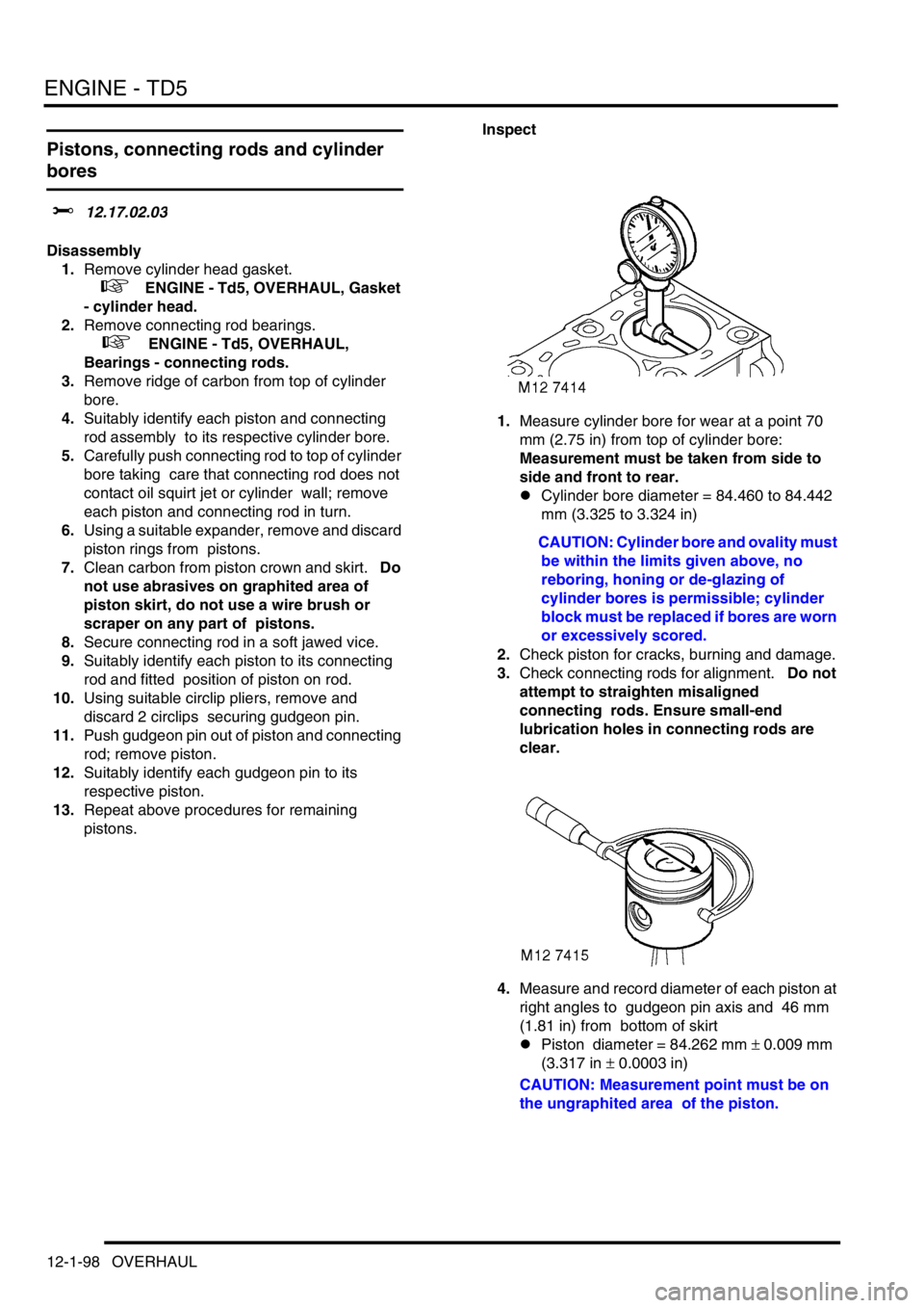
1.Measure cylinder bore for wear at a point 70
mm (2.75 in) from top of cylinder bore:
Measurement must be taken from side to
side and front to rear.
lCylinder bore diameter = 84.460 to 84.442
mm (3.325 to 3.324 in)
CAUTION: Cylinder bore and ovality must
be within the limits given above, no
reboring, honing or de-glazing of
cylinder bores is permissible; cylinder
block must be replaced if bores are worn
or excessively scored.
2.Check piston for cracks, burning and damage.
3.Check connecting rods for alignment. Do not
attempt to straighten misaligned
connecting rods. Ensure small-end
lubrication holes in connecting rods are
clear.
4.Measure and record diameter of each piston at
right angles to gudgeon pin axis and 46 mm
(1.81 in) from bottom of skirt
lPiston diameter = 84.262 mm
± 0.009 mm
(3.317 in
± 0.0003 in)
CAUTION: Measurement point must be on
the ungraphited area of the piston.
Page 238 of 1672
ENGINE - TD5
OVERHAUL 12-1-99
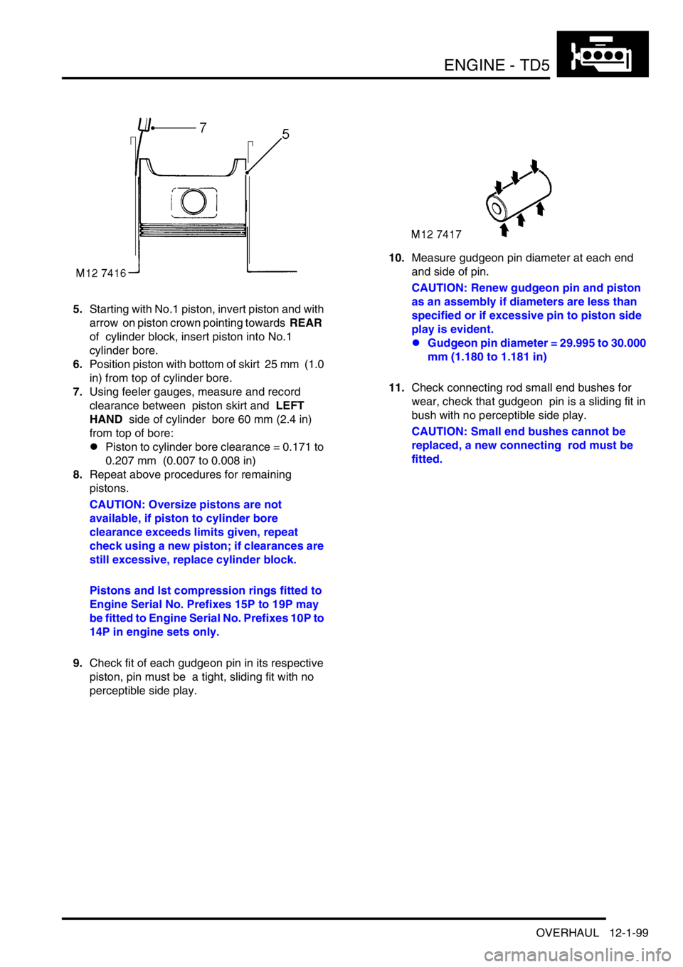
5.Starting with No.1 piston, invert piston and with
arrow on piston crown pointing towards REAR
of cylinder block, insert piston into No.1
cylinder bore.
6.Position piston with bottom of skirt 25 mm (1.0
in) from top of cylinder bore.
7.Using feeler gauges, measure and record
clearance between piston skirt and LEFT
HAND side of cylinder bore 60 mm (2.4 in)
from top of bore:
lPiston to cylinder bore clearance = 0.171 to
0.207 mm (0.007 to 0.008 in)
8.Repeat above procedures for remaining
pistons.
CAUTION: Oversize pistons are not
available, if piston to cylinder bore
clearance exceeds limits given, repeat
check using a new piston; if clearances are
still excessive, replace cylinder block.
Pistons and lst compression rings fitted to
Engine Serial No. Prefixes 15P to 19P may
be fitted to Engine Serial No. Prefixes 10P to
14P in engine sets only.
9.Check fit of each gudgeon pin in its respective
piston, pin must be a tight, sliding fit with no
perceptible side play.10.Measure gudgeon pin diameter at each end
and side of pin.
CAUTION: Renew gudgeon pin and piston
as an assembly if diameters are less than
specified or if excessive pin to piston side
play is evident.
lGudgeon pin diameter = 29.995 to 30.000
mm (1.180 to 1.181 in)
11.Check connecting rod small end bushes for
wear, check that gudgeon pin is a sliding fit in
bush with no perceptible side play.
CAUTION: Small end bushes cannot be
replaced, a new connecting rod must be
fitted.
Page 239 of 1672
ENGINE - TD5
12-1-100 OVERHAUL
12.Insert new compression and oil control rings in
turn into No.1 cylinder bore 30 mm (1.25 in)
from top of bore and check ring fitted gaps;
ensure rings are kept square to bore when
checking gaps:
l1st compression ring fitted gap = 0.30 to
0.40 mm (0.012 to 0.016 in).
l2nd compression ring fitted gap = 0.40 to
0.60 mm (0.016 to 0.024 in).
lOil control ring fitted gap = 0.25 to 0.50 mm
0.01 to 0.02 in).
CAUTION: 1st compression rings fitted to
Engine Serial No. Prefixes 10P to 14P are
not interchangeable with those fitted to
Engine Serial No. Prefixes 15P to 19P. The
later rings may, however, be fitted to early
engines together with the later type pistons
in engine sets only.
13.Repeat for each cylinder bore in turn.
CAUTION: Ensure rings are suitably
identified with the cylinder bore in which
they were checked and are fitted to the
piston for that bore.
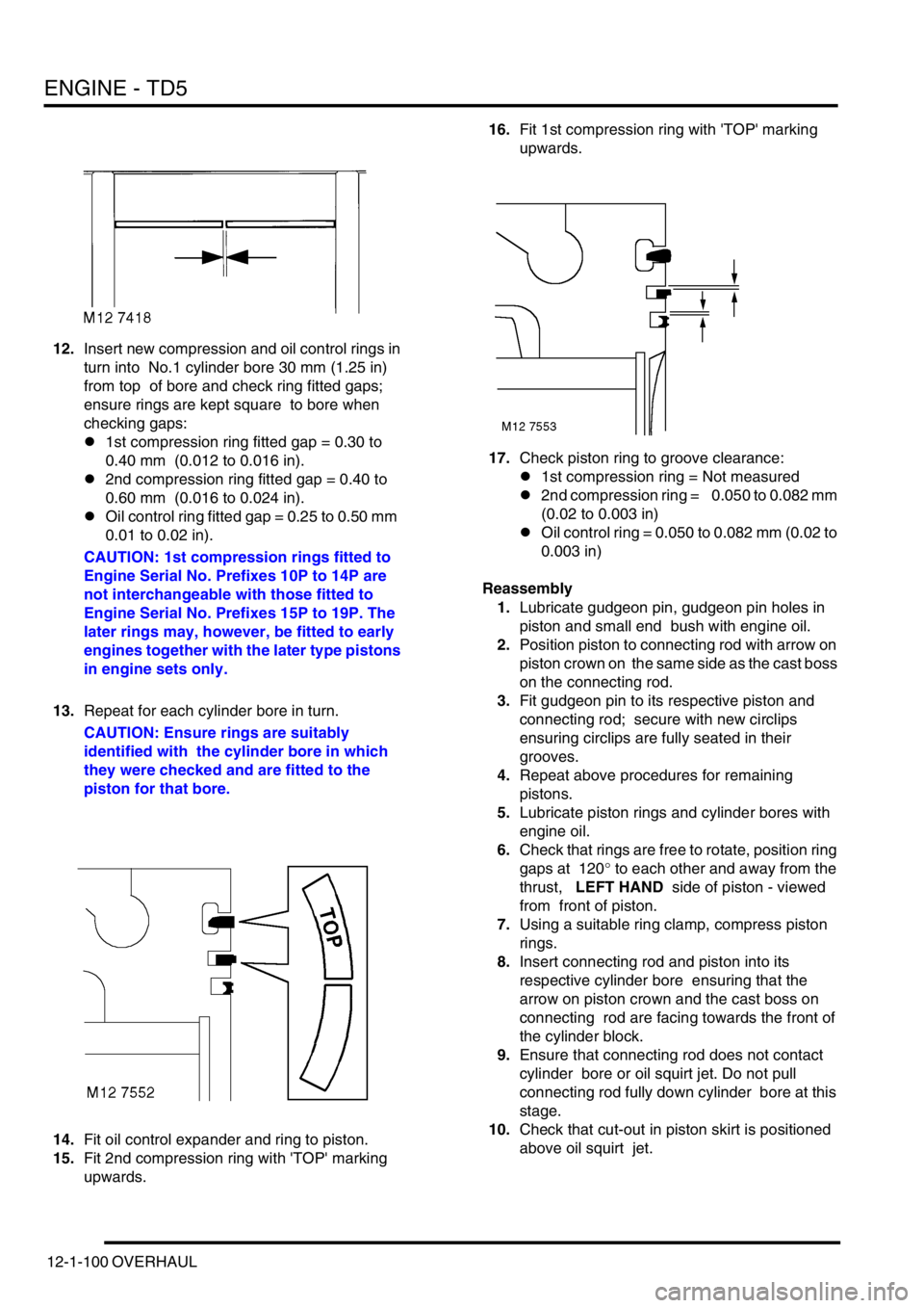
14.Fit oil control expander and ring to piston.
15.Fit 2nd compression ring with 'TOP' marking
upwards. 16.Fit 1st compression ring with 'TOP' marking
upwards.
17.Check piston ring to groove clearance:
l1st compression ring = Not measured
l2nd compression ring = 0.050 to 0.082 mm
(0.02 to 0.003 in)
lOil control ring = 0.050 to 0.082 mm (0.02 to
0.003 in)
Reassembly
1.Lubricate gudgeon pin, gudgeon pin holes in
piston and small end bush with engine oil.
2.Position piston to connecting rod with arrow on
piston crown on the same side as the cast boss
on the connecting rod.
3.Fit gudgeon pin to its respective piston and
connecting rod; secure with new circlips
ensuring circlips are fully seated in their
grooves.
4.Repeat above procedures for remaining
pistons.
5.Lubricate piston rings and cylinder bores with
engine oil.
6.Check that rings are free to rotate, position ring
gaps at 120
° to each other and away from the
thrust, LEFT HAND side of piston - viewed
from front of piston.
7.Using a suitable ring clamp, compress piston
rings.
8.Insert connecting rod and piston into its
respective cylinder bore ensuring that the
arrow on piston crown and the cast boss on
connecting rod are facing towards the front of
the cylinder block.
9.Ensure that connecting rod does not contact
cylinder bore or oil squirt jet. Do not pull
connecting rod fully down cylinder bore at this
stage.
10.Check that cut-out in piston skirt is positioned
above oil squirt jet.
Page 307 of 1672
ENGINE - V8
12-2-64 OVERHAUL
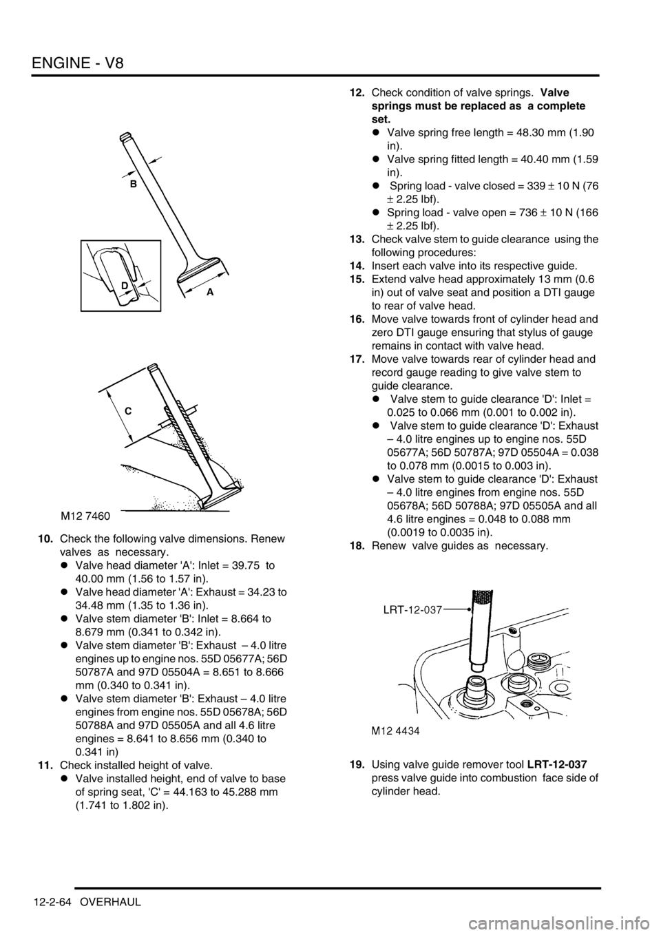
10.Check the following valve dimensions. Renew
valves as necessary.
lValve head diameter 'A': Inlet = 39.75 to
40.00 mm (1.56 to 1.57 in).
lValve head diameter 'A': Exhaust = 34.23 to
34.48 mm (1.35 to 1.36 in).
lValve stem diameter 'B': Inlet = 8.664 to
8.679 mm (0.341 to 0.342 in).
lValve stem diameter 'B': Exhaust – 4.0 litre
engines up to engine nos. 55D 05677A; 56D
50787A and 97D 05504A = 8.651 to 8.666
mm (0.340 to 0.341 in).
lValve stem diameter 'B': Exhaust – 4.0 litre
engines from engine nos. 55D 05678A; 56D
50788A and 97D 05505A and all 4.6 litre
engines = 8.641 to 8.656 mm (0.340 to
0.341 in)
11.Check installed height of valve.
lValve installed height, end of valve to base
of spring seat, 'C' = 44.163 to 45.288 mm
(1.741 to 1.802 in).12.Check condition of valve springs. Valve
springs must be replaced as a complete
set.
lValve spring free length = 48.30 mm (1.90
in).
lValve spring fitted length = 40.40 mm (1.59
in).
l Spring load - valve closed = 339
± 10 N (76
± 2.25 lbf).
lSpring load - valve open = 736
± 10 N (166
± 2.25 lbf).
13.Check valve stem to guide clearance using the
following procedures:
14.Insert each valve into its respective guide.
15.Extend valve head approximately 13 mm (0.6
in) out of valve seat and position a DTI gauge
to rear of valve head.
16.Move valve towards front of cylinder head and
zero DTI gauge ensuring that stylus of gauge
remains in contact with valve head.
17.Move valve towards rear of cylinder head and
record gauge reading to give valve stem to
guide clearance.
l Valve stem to guide clearance 'D': Inlet =
0.025 to 0.066 mm (0.001 to 0.002 in).
l Valve stem to guide clearance 'D': Exhaust
– 4.0 litre engines up to engine nos. 55D
05677A; 56D 50787A; 97D 05504A = 0.038
to 0.078 mm (0.0015 to 0.003 in).
lValve stem to guide clearance 'D': Exhaust
– 4.0 litre engines from engine nos. 55D
05678A; 56D 50788A; 97D 05505A and all
4.6 litre engines = 0.048 to 0.088 mm
(0.0019 to 0.0035 in).
18.Renew valve guides as necessary.
19.Using valve guide remover tool LRT-12-037
press valve guide into combustion face side of
cylinder head.
Page 310 of 1672
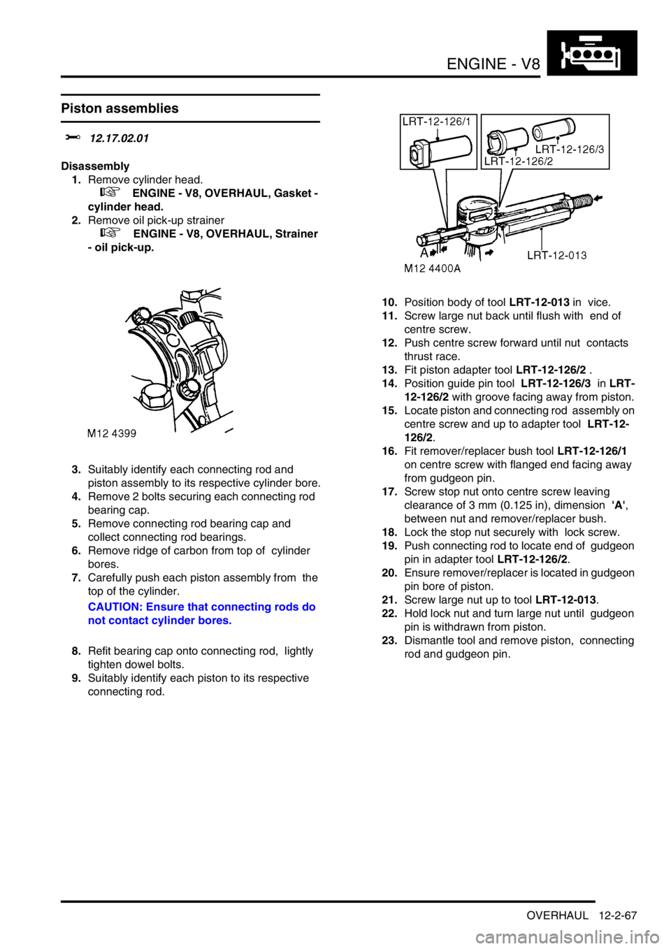
ENGINE - V8
OVERHAUL 12-2-67
Piston assemblies
$% 12.17.02.01
Disassembly
1.Remove cylinder head.
+ ENGINE - V8, OVERHAUL, Gasket -
cylinder head.
2.Remove oil pick-up strainer
+ ENGINE - V8, OVERHAUL, Strainer
- oil pick-up.
3.Suitably identify each connecting rod and
piston assembly to its respective cylinder bore.
4.Remove 2 bolts securing each connecting rod
bearing cap.
5.Remove connecting rod bearing cap and
collect connecting rod bearings.
6.Remove ridge of carbon from top of cylinder
bores.
7.Carefully push each piston assembly from the
top of the cylinder.
CAUTION: Ensure that connecting rods do
not contact cylinder bores.
8.Refit bearing cap onto connecting rod, lightly
tighten dowel bolts.
9.Suitably identify each piston to its respective
connecting rod.10.Position body of tool LRT-12-013 in vice.
11.Screw large nut back until flush with end of
centre screw.
12.Push centre screw forward until nut contacts
thrust race.
13.Fit piston adapter tool LRT-12-126/2 .
14.Position guide pin tool LRT-12-126/3 in LRT-
12-126/2 with groove facing away from piston.
15.Locate piston and connecting rod assembly on
centre screw and up to adapter tool LRT-12-
126/2.
16.Fit remover/replacer bush tool LRT-12-126/1
on centre screw with flanged end facing away
from gudgeon pin.
17.Screw stop nut onto centre screw leaving
clearance of 3 mm (0.125 in), dimension 'A',
between nut and remover/replacer bush.
18.Lock the stop nut securely with lock screw.
19.Push connecting rod to locate end of gudgeon
pin in adapter tool LRT-12-126/2.
20.Ensure remover/replacer is located in gudgeon
pin bore of piston.
21.Screw large nut up to tool LRT-12-013.
22.Hold lock nut and turn large nut until gudgeon
pin is withdrawn from piston.
23.Dismantle tool and remove piston, connecting
rod and gudgeon pin.
Page 313 of 1672
ENGINE - V8
12-2-70 OVERHAUL
23.Fit 2nd compression ring marked 'TOP' with
marking uppermost in 2nd groove.
24.Fit 1st compression ring in first groove either
way round.
25.Check piston ring to groove clearance.
l1st compression ring = 0.05 to 0.10 mm
(0.002 to 0.004 in).
l2nd compression ring = 0.05 to 0.10 mm
(0.002 to 0.004 in).
26.Position oil control expander ring joint and ring
rail gaps all at one side, between gudgeon pin
and away from LH side of piston - viewed from
front of piston. Position the gaps in ring rails
approximately 25 mm (1.0 in) each side of
expander ring joint.
27.Position compression rings with gaps on
opposite side of piston between gudgeon pin
and RH side of piston - viewed from front of
piston.
28.Thoroughly clean cylinder bores.
29.Lubricate piston rings and gudgeon pin with
clean engine oil.
30.Lubricate cylinder bore with clean engine oil.
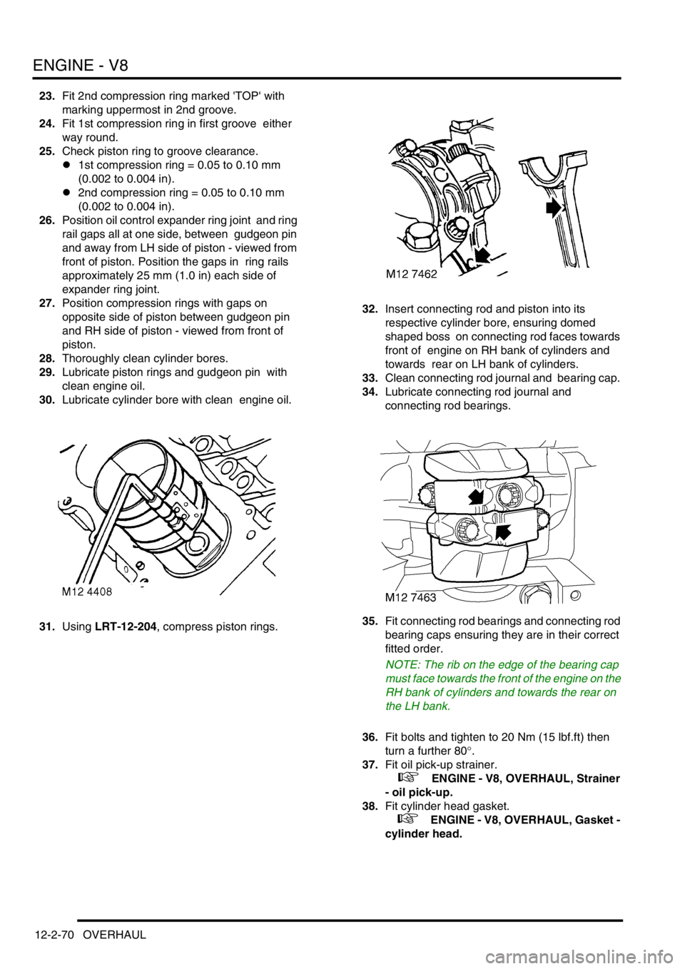
31.Using LRT-12-204, compress piston rings. 32.Insert connecting rod and piston into its
respective cylinder bore, ensuring domed
shaped boss on connecting rod faces towards
front of engine on RH bank of cylinders and
towards rear on LH bank of cylinders.
33.Clean connecting rod journal and bearing cap.
34.Lubricate connecting rod journal and
connecting rod bearings.
35.Fit connecting rod bearings and connecting rod
bearing caps ensuring they are in their correct
fitted order.
NOTE: The rib on the edge of the bearing cap
must face towards the front of the engine on the
RH bank of cylinders and towards the rear on
the LH bank.
36.Fit bolts and tighten to 20 Nm (15 lbf.ft) then
turn a further 80
°.
37.Fit oil pick-up strainer.
+ ENGINE - V8, OVERHAUL, Strainer
- oil pick-up.
38.Fit cylinder head gasket.
+ ENGINE - V8, OVERHAUL, Gasket -
cylinder head.
Page 325 of 1672
EMISSION CONTROL - TD5
17-1-4 DESCRIPTION AND OPERATION
Emission Control Systems
Engine design has evolved in order to minimise the emission of harmful by-products. Emission control systems fitted
to Land Rover vehicles are designed to maintain the emission levels within the legal limits pertaining for the specified
market.
Despite the utilisation of specialised emission control equipment, it is still necessary to ensure that the engine is
correctly maintained and is in good mechanical order, so that it operates at its optimum condition.
In addition to emissions improvements through engine design and the application of electronic engine management
systems, special emission control systems are used to limit the pollutant levels developed under certain conditions.
Two main types of additional emission control system are utilised with the Td5 engine to reduce the levels of harmful
emissions released into the atmosphere. These are as follows:
1Crankcase emission control – also known as blow-by gas emissions from the engine crankcase.
2Exhaust gas recirculation – to reduce NO
2 emissions.
Crankcase emission control
All internal combustion engines generate oil vapour and smoke in the crankcase as a result of high crankcase
temperatures and piston ring and valve stem blow-by, a closed crankcase ventilation system is used to vent
crankcase gases back to the air induction system and so reduce the emission of hydrocarbons.
Gases from the crankcase are drawn into the inlet manifold to be burnt in the combustion chambers with the fresh air/
fuel mixture. The system provides effective emission control under all engine operating conditions.
Crankcase gases are drawn through the breather port in the top of the camshaft cover and routed through the breather
hose and breather valve on the flexible air intake duct to be drawn into the turbocharger intake for delivery to the air
inlet manifold via an intercooler.
An oil separator plate is included in the camshaft cover which removes the heavy particles of oil before the crankcase
gas leaves via the camshaft cover port. The rocker cover features circular chambers which promote swirl in the oil
mist emanating from the cylinder head and camshaft carrier. As the mist passes through the series of chambers
between the rocker cover and oil separator plate, oil particles are thrown against the separator walls where they
condense and fall back into the cylinder head via two air inlet holes located at each end of the rocker cover.
The breather valve is a depression limiting valve which progressively closes as engine speed increases, thereby
limiting the depression in the crankcase. The valve is of moulded plastic construction and has a port on the underside
which plugs into a port in the flexible air intake duct. A port on the side of the breather valve connects to the camshaft
cover port by means of a breather hose which is constructed from a heavy-duty braided rubber hose which is held in
place by hose clips. A corrugated plastic sleeve is used to give further protection to the breather hose. The breather
valve is orientation sensitive, and “TOP” is marked on the upper surface to ensure it is mounted correctly.
It is important that the system is airtight so hose connections to ports should be checked and the condition of the
breather hose should be periodically inspected to ensure it is in good condition.
Page 327 of 1672
EMISSION CONTROL - TD5
17-1-6 DESCRIPTION AND OPERATION
The EGR modulator is located on a plate fixed to the inner wing on the RH side of the engine. The modulator is
attached to the plate by two through-studs, each with two nuts which secure the modulator assembly to a rubber
mounting which helps to reduce noise. The modulator must be mounted in the vertical orientation with the two vacuum
ports uppermost.
The modulator operation is controlled by a signal from the ECM which determines the required amount of EGR
needed in response to inputs relating to air flow and engine operating and ambient conditions. The modulator has a
black two-pin connector at its base to connect it to the ECM through the engine harness.
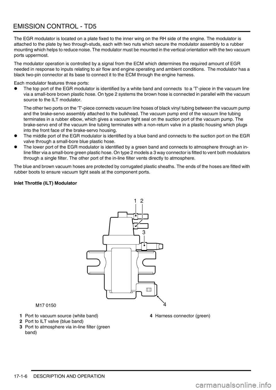
Each modulator features three ports:
lThe top port of the EGR modulator is identified by a white band and connects to a 'T'-piece in the vacuum line
via a small-bore brown plastic hose. On type 2 systems the brown hose is connected in parallel with the vacuum
source to the ILT modulator.
The other two ports on the 'T'-piece connects vacuum line hoses of black vinyl tubing between the vacuum pump
and the brake-servo assembly attached to the bulkhead. The vacuum pump end of the vacuum line tubing
terminates in a rubber elbow, which gives a vacuum tight seal on the suction port of the vacuum pump. The
brake-servo end of the vacuum line tubing terminates with a non-return valve in a plastic housing which plugs
into the front face of the brake-servo housing.
lThe middle port of the EGR modulator is identified by a blue band and connects to the suction port on the EGR
valve through a small-bore blue plastic hose.
lThe lower port of the EGR modulator is identified by a green band and connects to atmosphere through an in-
line filter via a small-bore green plastic hose. On type 2 models a 3 way connector is fitted to vent both modulators
through a single filter. The other port of the in-line filter vents directly to atmosphere.
The blue and brown vacuum hoses are protected by corrugated plastic sheaths. The ends of the hoses are fitted with
rubber boots to ensure vacuum tight seals at the component ports.
Inlet Throttle (ILT) Modulator
1Port to vacuum source (white band)
2Port to ILT valve (blue band)
3Port to atmosphere via in-line filter (green
band)4Harness connector (green)
Page 328 of 1672
EMISSION CONTROL - TD5
DESCRIPTION AND OPERATION 17-1-7
The ILT modulator is located on a plate fixed to the inner wing on the RH side of the engine below the EGR modulator.
The modulator is attached to the plate by two through-studs, each with two nuts which secure the modulator assembly
to a rubber mounting which helps to reduce noise. The modulator must be mounted in the vertical orientation with the
two vacuum ports uppermost.
The modulator operation is controlled by a signal from the ECM which determines the required ratio of exhaust gas
to fresh inlet air needed in response to inputs relating to air flow and engine operating and ambient conditions. The
modulator has a green two-pin connector at its base to connect it to the ECM through the engine harness.
The ILT valve modulator features three ports:
lThe top port is identified by a white band and connects to a 'T'-piece in the vacuum line via a small-bore brown
plastic hose where it is connected in parallel with the vacuum source line to the EGR valve modulator. The two
other ports on the 'T'-piece connect vacuum line hoses of black vinyl tubing between the vacuum pump attached
to the alternator and the brake-servo assembly attached to the bulkhead.
lThe middle port is identified by a blue band and connects to the suction port on the ILT valve through a small-
bore blue plastic hose.
lThe lower port is identified by a green band and connects to atmosphere through an in-line filter via a green
plastic hose and a three-way connector positioned in-line between the modulators and the filter. The ILT
modulator hose is connected opposite to the two parallel ports at the three-way connector which connect the vent
lines to the EGR valve modulator and the in-line filter. The other port of the in-line filter vents directly to
atmosphere.
The blue and brown vacuum hoses are protected by corrugated plastic sheaths. The ends of the hoses are fitted with
rubber boots to ensure vacuum tight seals at the component ports.
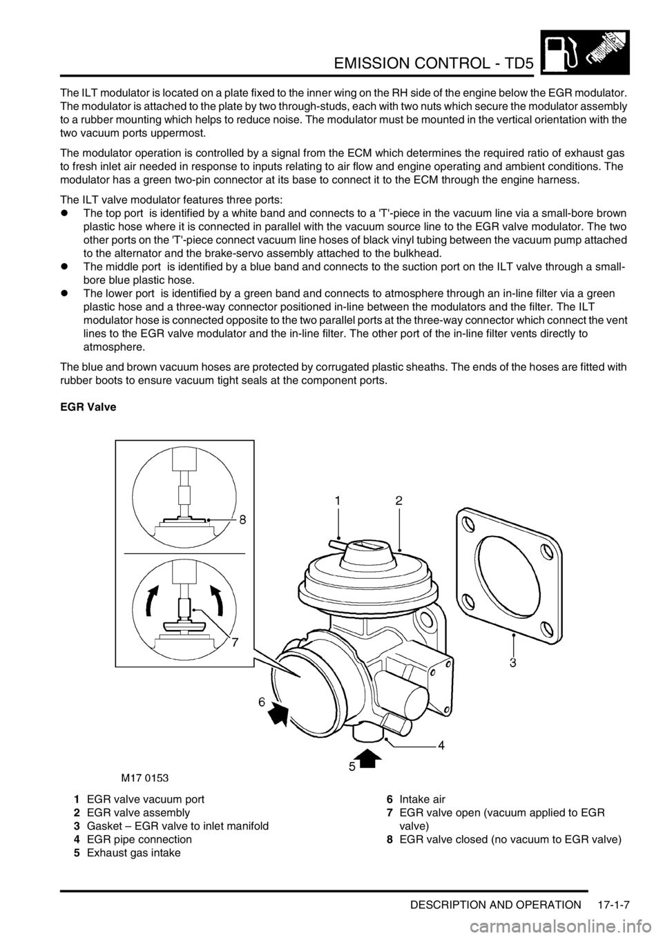
EGR Valve
1EGR valve vacuum port
2EGR valve assembly
3Gasket – EGR valve to inlet manifold
4EGR pipe connection
5Exhaust gas intake6Intake air
7EGR valve open (vacuum applied to EGR
valve)
8EGR valve closed (no vacuum to EGR valve)
Page 331 of 1672
EMISSION CONTROL - TD5
17-1-10 DESCRIPTION AND OPERATION
EGR systems
There are two types of exhaust gas recirculation system used with the Td5 engine dependent on legislation and
market requirements, these are type 1 and type 2.
Type 1 EGR system is fitted to all Td5's built up to the introduction of 2002 MY, except for Japanese specification
vehicles.
Type 2 EGR system is fitted to all Japanese specification vehicles and was introduced into European markets for 2002
MY to meet EU3 emission requirements. An additional feature introduced at 2002 MY is the EGR cooler, which is
bolted to the front of the cylinder head.
EGR system - type 1
This EGR system features a single modulator which is electrically controlled to modulate a vacuum source to the EGR
valve. The controlled vacuum opens and closes the valve by the amount required to ensure the optimal proportion of
exhaust gas is allowed through to the inlet manifold to be combined with the fresh air intake. Control feedback is
achieved by monitoring the mass of fresh air flowing through the mass air flow sensor.
The modulator operation is controlled by a signal from the ECM which determines the required amount of EGR
needed in response to inputs relating to air flow and engine operating and ambient conditions. The ECM is low-side
driven, sinking current returned from the vacuum modulator for switching operating condition.
The exhaust gases are routed from the exhaust manifold through a shaped metal pipe which connects to the
underside of the EGR valve. The pipe is held securely in position to the front of the cylinder head using a clamp
bracket. The EGR pipe is attached to a mating port at the front end of the exhaust manifold using two Allen screws
and at the EGR valve assembly by a metal band clamp. The two Allen screws fixing the EGR pipe to the exhaust
manifold should be replaced every time the EGR pipe is removed. Extreme care should be exercised when
removing and refitting the EGR pipe to avoid damage.
When a vacuum is applied to the EGR suction port, it causes a spindle with sealing disc (EGR valve) to be raised,
thus opening the port at the EGR pipe to allow the recirculated exhaust gas to pass through into the inlet manifold.
The valve is spring loaded so that when the vacuum is removed from the suction port the valve returns to its rest
position to tightly close the exhaust gas port.
By controlling the quantity of recirculated exhaust gas available in the inlet manifold, the optimum mix for the prevailing
engine operating conditions can be maintained, which ensures the intake gas to the combustion chambers will have
burning rate properties which will reduce the NO
x emissions to an acceptable level. Normally, full recirculation is only
applicable when the NO
x emissions are most prevalent.
EGR system - type 2
This system features twin modulators mounted one above the other on a metal plate located on the inner wing at the
RH side of the engine. The modulators are electrically controlled by the engine management system and are used to
modulate a vacuum source to the EGR valve and a supplementary Inlet Throttle (ILT) valve; the two valves are
controlled to operate in tandem. The ILT valve vacuum pot is mounted adjacent to the EGR valve housing and has a
linkage which connects to a butterfly valve mounted in front of the EGR valve at the air intake manifold.
The modulator operations are electrically controlled by signals from the engine management system which
determines the required volume of exhaust gas needed in response to inputs relating to air flow, engine operating
conditions and ambient parameters such as temperature and altitude. The engine management ECM switches on the
circuit by completing the path to ground, operating the vacuum modulators.
Pre EU3 models: The exhaust gases are routed from the exhaust manifold through a shaped metal pipe which
connects to the underside of the EGR valve. The pipe is held securely in position to the front of the engine cylinder
head using a metal clamp bracket. The EGR pipe is attached to a mating port at the front end of the exhaust manifold
using two Allen screws and at the EGR valve assembly by a metal band clamp. The two Allen screws fixing the EGR
pipe to the exhaust manifold should be replaced every time the EGR pipe is removed. Extreme care should be
exercised when removing and refitting the EGR pipe to avoid damage.