air filter LAND ROVER DISCOVERY 2002 Owner's Manual
[x] Cancel search | Manufacturer: LAND ROVER, Model Year: 2002, Model line: DISCOVERY, Model: LAND ROVER DISCOVERY 2002Pages: 1672, PDF Size: 46.1 MB
Page 151 of 1672

ENGINE - TD5
12-1-12 DESCRIPTION AND OPERATION
Description
General
The Td5 diesel engine is a 2.5 litre, 5 cylinder, in-line direct injection unit having 2 valves per cylinder, operated by a
single overhead camshaft. The engine emissions, on pre EU3 models, comply with ECD2 (European Commission
Directive) and on EU3 models, comply with ECD3 legislative requirements. Both models employ electronic engine
management control, positive crankcase ventilation and exhaust gas recirculation to limit the emission of pollutants.
The unit is water cooled and turbo-charged and is controlled by an electronic engine management system.
The engine is a monobloc cast iron construction with an aluminium stiffening plate fitted to the bottom of the cylinder
block to improve lower structure rigidity. The cylinder head and sump are cast aluminium. An acoustic cover is fitted
over the upper engine to reduce engine generated noise.
The engine utilises the following features:
lElectronic Unit Injectors (EUI's) controlled by an Engine Management System for precise fuel delivery under
all prevailing operating conditions.
lTurbocharging which delivers compressed air to the combustion chambers via an intercooler for improved
power output.
lFuel Cooler
lOil Cooler
lCentrifuge Oil Filter
lHydraulic Lash Adjusters with independent finger followers
Cylinder block components
The cylinder block components are described below:
Cylinder Block
The cylinders and crankcase are contained in a single cast iron construction. The cylinders are direct bored and
plateau honed with lubrication oil supplied via lubrication jets for piston and gudgeon pin lubrication and cooling. It is
not possible to rebore the cylinder block if the cylinders become worn or damaged. Three metal core plugs are fitted
to the three centre cylinders on the right hand side of the cylinder block.
Lubrication oil is distributed throughout the block via the main oil gallery to critical moving parts through channels
bored in the block which divert oil to the main and big-end bearings via oil holes machined into the crankshaft. Oil is
also supplied from the cylinder block main gallery to the five lubrication jets which cool and lubricate the piston and
gudgeon pins. Plugs are used to seal both ends of the main oil gallery at front and rear of the engine block. An oil
cooler is fitted to the LH side of the engine block; ports in the oil cooler assembly mate with ports in the cylinder block
to facilitate coolant flow. Oil is diverted through the oil cooler, centrifuge filter and full-flow filter before supplying the
main oil gallery. A tapping in the oil filter housing provides a lubrication source for the turbocharger bearings and an
oil pressure switch is included in a tapping in the oil cooler housing which determines whether sufficient oil pressure
is available to provide engine lubrication and cooling.
Cylinder cooling is achieved by water circulating through chambers in the engine block casting. A threaded coolant
jacket plug is located at the front RH side of the cylinder block.
Cast mounting brackets are bolted to both sides of the engine block for mounting the engine to the chassis on the LH
and RH hydramount studs.
The gearbox bolts directly to the engine block; a gearbox shim plate is located between the adjoining faces of the
gearbox and the flywheel side of the engine block and is fixed to the rear of the engine block by two bolts. Two hollow
metal dowels locate the rear of the cylinder block to the gearbox shim plate. The gearbox casing provides the
mounting for the starter motor.
A port is included at the rear left hand side of the cylinder block which connects to the turbocharger oil drain pipe to
return lubrication oil to the sump.
A plug sealing the lubrication cross-drilling gallery is located at the front right hand side of the cylinder block and plugs
for the main lubrication gallery is included at the front and rear of the cylinder block.
Page 192 of 1672

ENGINE - TD5
REPAIRS 12-1-53
Mounting - front - LH
$% 12.45.01
Remove
1.Remove centrifuge assembly.
+ ENGINE - Td5, REPAIRS, Gasket -
centrifuge oil drain pipe.
2.Remove 3 bolts, remove oil filter adaptor
housing and discard gasket.
3.Fit suitable lifting chains to support engine.
4.With assistance remove 2 bolts securing
engine mounting to chassis.
5.Remove 4 bolts securing engine mounting
bracket to cylinder block.
6.Remove nut securing mounting to mounting
bracket.
7.Remove mounting and mounting bracket.
8.Remove mounting shield.
Refit
1.Fit shield to mounting. 2.Fit mounting and mounting bracket.
3.Fit mounting bracket to cylinder block and
tighten – bolts securing front LH engine
mounting bracket to cylinder block to 48 Nm (35
lbf.ft).
4.With assistance, fit mounting to chassis and
tighten – bolts securing front LH engine
mounting to chassis to 85 Nm (63 lbf.ft).
5.Fit mounting to mounting bracket and tighten –
nut securing front LH mounting to mounting
bracket to 85 Nm (63 lbf.ft).
6.Remove engine support chains.
7.Clean oil filter adaptor housing and mating
face.
8.Fit oil filter adaptor housing to oil cooler
housing and tighten bolts to 25 Nm (18 lbf.ft).
9.Fit centrifuge assembly.
+ ENGINE - Td5, REPAIRS, Gasket -
centrifuge oil drain pipe.
Page 196 of 1672

ENGINE - TD5
REPAIRS 12-1-57
Filter - oil
$% 12.60.04
Remove
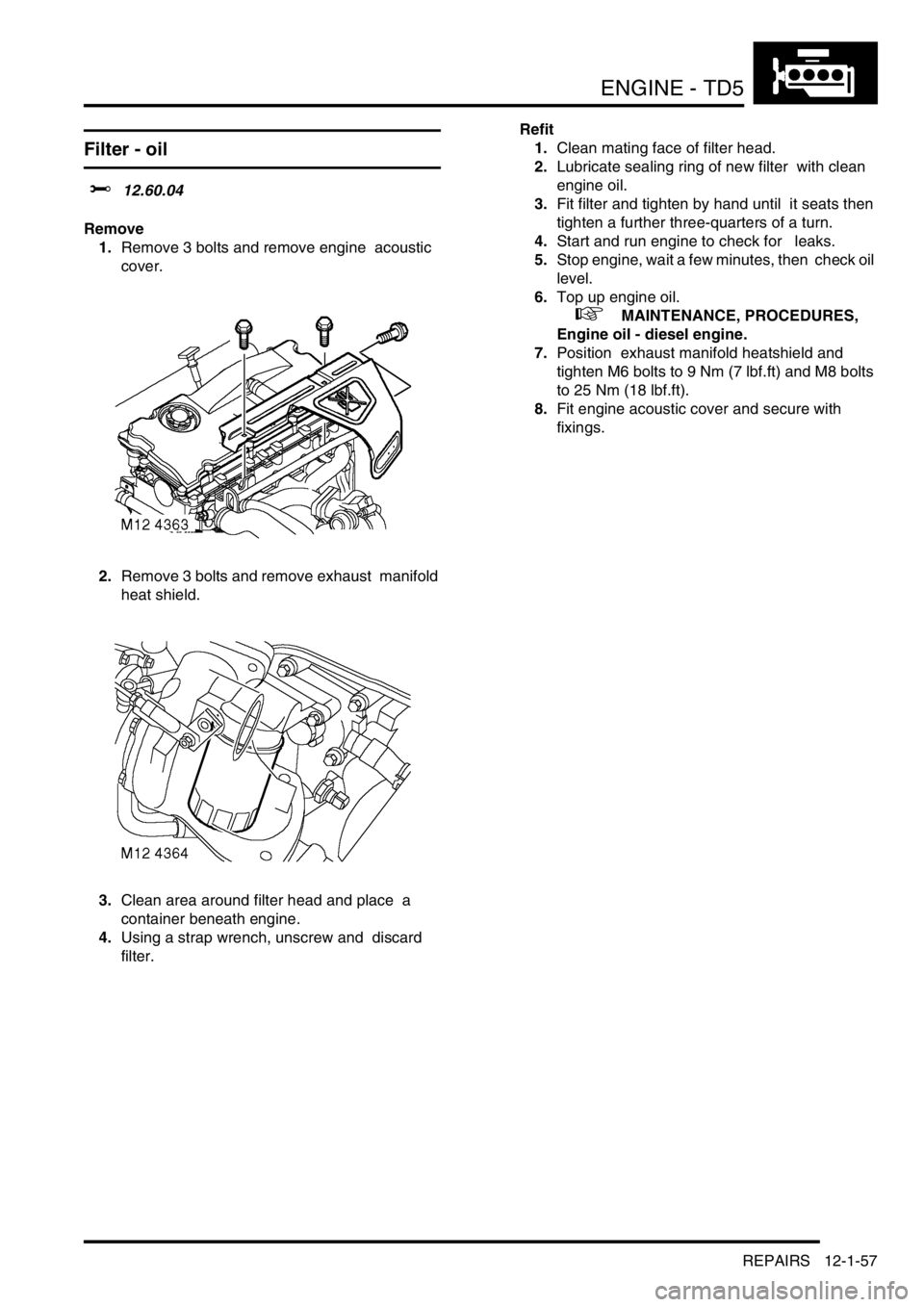
1.Remove 3 bolts and remove engine acoustic
cover.
2.Remove 3 bolts and remove exhaust manifold
heat shield.
3.Clean area around filter head and place a
container beneath engine.
4.Using a strap wrench, unscrew and discard
filter. Refit
1.Clean mating face of filter head.
2.Lubricate sealing ring of new filter with clean
engine oil.
3.Fit filter and tighten by hand until it seats then
tighten a further three-quarters of a turn.
4.Start and run engine to check for leaks.
5.Stop engine, wait a few minutes, then check oil
level.
6.Top up engine oil.
+ MAINTENANCE, PROCEDURES,
Engine oil - diesel engine.
7.Position exhaust manifold heatshield and
tighten M6 bolts to 9 Nm (7 lbf.ft) and M8 bolts
to 25 Nm (18 lbf.ft).
8.Fit engine acoustic cover and secure with
fixings.
Page 202 of 1672

ENGINE - TD5
REPAIRS 12-1-63
Refit
1.Clean oil pressure switch threads.
2.Fit oil pressure switch and tighten to 15 Nm (11
lbf.ft).
3.Connect multiplug to oil pressure switch.
4.Position exhaust manifold heatshield and
tighten M6 bolts to 9 Nm (7 lbf.ft) and M8 bolts
to 25 Nm (18 lbf.ft).
5.Fit and secure engine acoustic cover.
6.Top up engine oil.
+ MAINTENANCE, PROCEDURES,
Engine oil - diesel engine.
Cooler - engine oil
$% 12.60.68
Remove
1.Drain cooling system.
+ COOLING SYSTEM - Td5,
ADJUSTMENTS, Drain and refill.
2.Remove centrifuge assembly.
+ ENGINE - Td5, REPAIRS, Gasket -
centrifuge oil drain pipe.
3.Remove clutch housing bolt and release
coolant pipe from rear of engine.
4.Release clip and coolant hose from oil cooler.
5.Disconnect multiplug from oil pressure switch.
6.Remove full-flow oil filter element using a
suitable strap wrench.
7.Remove 3 bolts, remove oil filter adaptor
housing and discard gasket.
8.Remove 7 bolts, remove oil cooler and discard
gasket.
9.Remove oil pressure switch.
Page 203 of 1672

ENGINE - TD5
12-1-64 REPAIRS
Refit
1.Clean oil cooler and mating faces.
2.Fit oil pressure switch and tighten to 9 Nm (7
lbf.ft).
3.Position new gasket and fit oil cooler housing,
tighten bolts to 25 Nm (18 lbf.ft).
4.Position and fit oil filter adaptor housing,
tighten bolts to 25 Nm (18 lbf. ft).
5.Fit oil filter, tighten hand tight then a further half
turn.
6.Position coolant hose to oil cooler and secure
clip.
7.Position coolant pipe bolt and tighten to 50 Nm
(37 lbf.ft) .
8.Connect multiplug to oil pressure switch.
9.Fit centrifuge assembly.
+ ENGINE - Td5, REPAIRS, Gasket -
centrifuge oil drain pipe.
10.Refill cooling system.
+ COOLING SYSTEM - Td5,
ADJUSTMENTS, Drain and refill.
11.Top up engine oil.
+ MAINTENANCE, PROCEDURES,
Engine oil - diesel engine.
Gasket - centrifuge oil drain pipe
$% 12.60.90
Remove
1.Raise front of vehicle.
WARNING: Do not work on or under a
vehicle supported only by a jack. Always
support the vehicle on safety stands.
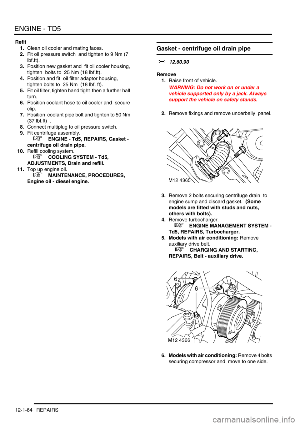
2.Remove fixings and remove underbelly panel.
3.Remove 2 bolts securing centrifuge drain to
engine sump and discard gasket. (Some
models are fitted with studs and nuts,
others with bolts).
4.Remove turbocharger.
+ ENGINE MANAGEMENT SYSTEM -
Td5, REPAIRS, Turbocharger.
5. Models with air conditioning: Remove
auxiliary drive belt.
+ CHARGING AND STARTING,
REPAIRS, Belt - auxiliary drive.
6. Models with air conditioning: Remove 4 bolts
securing compressor and move to one side.
Page 252 of 1672

ENGINE - V8
DESCRIPTION AND OPERATION 12-2-9
element. Oil from the filter passes into the main oil gallery and through internal drillings to the crankshaft where it is
directed to each main bearing and to the big-end bearings via numbers 1, 3 and 5 main bearings. An internal drilling
in the cylinder block directs oil to the camshaft where it passes through further internal drillings to the hydraulic
tappets, camshaft bearing journals and rocker shafts. Lubrication to the pistons, small ends and cylinder bores is by
oil grooves machined in the connecting rods and by splash.
Oil pressure switch
The oil pressure warning light switch registers low oil pressure in the main oil gallery on the outflow side of the filter.
Whilst the engine is running and oil pressure is correct, the switch is open. When the ignition is switched on or if oil
pressure drops below the pressure setting of the switch, the switch closes and the low oil pressure warning lamp
located in the instrument pack will illuminate.
Hydraulic tappets
1Clip
2Pushrod seat
3Inner sleeve
4Upper chamber5Non-return ball valve
6Spring
7Outer sleeve
8Lower chamber
The hydraulic tappet provides maintenance free, quiet operation of the valves. This is achieved by utilizing engine oil
pressure to eliminate the clearance between the rocker arms and valve stems. When the valve is closed, engine oil
pressure present in the upper chamber, passes through the non-return ball valve and into the lower chamber. When
the cam begins to lift the outer sleeve, the resistance of the valve spring, felt through the push rod and seat, causes
the tappet inner sleeve to move downwards inside the outer sleeve. This downwards movement closes the non-return
ball valve and increases the pressure in the lower chamber sufficiently to ensure that the valve is fully opened by the
push rod. As the tappet moves off the peak of the cam, the non-return ball valve opens thereby allowing the pressure
in both chambers to equalize. This ensures that the valve will be fully closed when the tappet is on the back of the
cam.
Crankcase ventilation
A positive crankcase ventilation system is used to vent crankcase gases to the air induction system. Gases are drawn
from the left hand rocker cover to a tapping in the throttle body. An oil separator is incorporated in the hose connection
stub pipe in the right hand rocker cover, gases from this connection are drawn to a tapping in the inlet manifold.
+ EMISSION CONTROL - V8, DESCRIPTION AND OPERATION, Crankcase emission control system.
Page 269 of 1672

ENGINE - V8
12-2-26 REPAIRS
Engine assembly
$% 12.41.01.99
Remove
1.Drain engine oil and remove oil filter.
2.Remove radiator.
+ COOLING SYSTEM - V8, REPAIRS,
Radiator.
3.Remove upper inlet manifold.
+ MANIFOLDS AND EXHAUST
SYSTEMS - V8, REPAIRS, Gasket - inlet
manifold - upper - Without Secondary Air
Injection.
4.Remove ignition coil assemblies.
5.Position absorbent material to catch spillage
and disconnect fuel pipe from fuel rail.
CAUTION: Always fit plugs to open
connections to prevent contamination.
6.Release 2 hose clips and remove top hose.
7.Using a 15 mm spanner, release auxiliary drive
belt tension and remove drive belt. 8.Remove 3 bolts securing ACE pump, release
pump and tie aside.
9.Disconnect multiplug from A/C compressor.
10.Remove 4 bolts securing A/C compressor,
release compressor and tie aside.
Page 273 of 1672

ENGINE - V8
12-2-30 REPAIRS
Refit
1.Clean mating faces of engine and gearbox,
dowel and dowel holes.
2.Lubricate splines and bearing surface on first
motion shaft with grease.
3.With assistance position engine in engine bay,
align to gearbox and locate on dowels.
4.Position support brackets, fit bell housing bolts
and tighten to 50 Nm (37 lbf.ft).
5.Position engine mountings, fit nuts and tighten
to 85 Nm (63 lbf.ft).
6.Lower lifting equipment and remove from
engine.
7. Models with automatic gearbox: Align torque
converter to drive plate, fit bolts and tighten to
50 Nm (37 lbf.ft). Fit access plug.
8.Fit exhaust front pipe.
+ MANIFOLDS AND EXHAUST
SYSTEMS - V8, REPAIRS, Front pipe.
9.Position oil cooling pipe saddle clamps and
tighten bolts.
10.Position engine harness into foot well.
11.Connect 5 multiplugs to ECM.
12.Fit toe board and secure with trim fixings.
13.Connect engine harness earth to body and
secure with nut.
14.Connect engine harness to main harness
multiplug.
15.Connect multiplug to EVAP purge valve.
16.Connect engine harness multiplugs to fuse
box.
17.Connect starter lead to fuse box and secure
with nut.
18.Connect engine harness positive lead to
battery and tighten nut.
19.Fit fuse box cover.
20.Position engine earth lead and secure with
bolt.
21.Position coolant rail and secure with bolt.
22.Connect harness clips to coolant rail.
23.Connect hose to coolant rail and coolant pump
and secure with clips.
24.Connect PAS pump high and low pressure
pipes and secure with clips.
25.Position oil cooling pipe saddle clamp to PAS
pump housing and secure with bolt.
26.Clean A/C compressor and housing mating
faces, dowels and dowel holes. 27.Position A/C compressor, fit bolts and tighten
to 22 Nm (16 lbf.ft).
28.Connect multiplug to A/C compressor.
29.Clean ACE pump and housing mating faces,
dowels and dowel holes.
30.Position ACE pump, fit bolts and tighten to 22
Nm (16 lbf.ft).
31.Clean all pulley 'V's, fit auxiliary drive belt,
using a 15mm spanner, release belt tensioner
secure belt and re-tension drive belt .
32.Ensure auxiliary drive belt is correctly located
on all pulleys.
33.Fit radiator.
+ COOLING SYSTEM - V8, REPAIRS,
Radiator.
34.Fit top hose and secure with clips.
35.Connect fuel pipe to fuel rail.
36.Position ignition coils and connect ht leads.
37.Fit upper inlet manifold.
+ MANIFOLDS AND EXHAUST
SYSTEMS - V8, REPAIRS, Gasket - inlet
manifold - upper - Without Secondary Air
Injection.
38.Fit new oil filter and refill engine with oil.
+ ENGINE - V8, REPAIRS, Filter - oil.
+ MAINTENANCE, PROCEDURES,
Engine oil - V8 engine.
39.Top up gearbox oil.
+ MAINTENANCE, PROCEDURES,
Automatic gearbox.
Page 277 of 1672

ENGINE - V8
12-2-34 REPAIRS
4.Ensure ring gear is correctly seated around the
complete circumference of flywheel and allow
to cool.
5.Fit flywheel.
+ ENGINE - V8, REPAIRS, Flywheel.
Filter - oil
$% 12.60.04
Remove
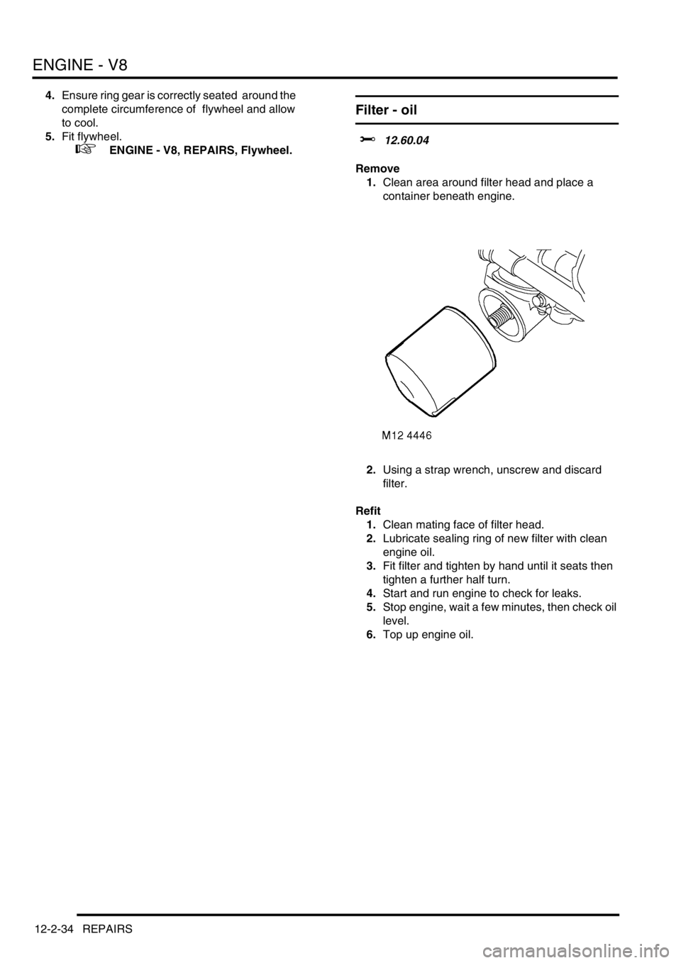
1.Clean area around filter head and place a
container beneath engine.
2.Using a strap wrench, unscrew and discard
filter.
Refit
1.Clean mating face of filter head.
2.Lubricate sealing ring of new filter with clean
engine oil.
3.Fit filter and tighten by hand until it seats then
tighten a further half turn.
4.Start and run engine to check for leaks.
5.Stop engine, wait a few minutes, then check oil
level.
6.Top up engine oil.
Page 278 of 1672

ENGINE - V8
REPAIRS 12-2-35
Strainer - oil pick-up
$% 12.60.20
Remove
1.Remove sump gasket.
+ ENGINE - V8, REPAIRS, Gasket -
sump.
2.Remove 2 bolts and one nut securing oil pick-
up strainer.
3.Remove oil pick-up strainer.
4.Collect spacer from stud.
5.Remove and discard 'O'ring.
Refit
1.Clean oil pick up strainer and 'O' ring recess.
2.Lubricate and fit new 'O' ring.
3.Locate spacer on stud.
4.Position oil pick-up strainer, fit bolts and tighten
to 10 Nm (8 lbf.ft). Fit nut and tighten to 22 Nm
(16 lbf.ft).
5.Fit new sump gasket.
+ ENGINE - V8, REPAIRS, Gasket -
sump.
Pump - oil
$% 12.60.26
Remove
1.Remove timing gear cover gasket.
+ ENGINE - V8, REPAIRS, Gasket -
timing gear cover.
2.Remove bolt securing CMP sensor, remove
clamp and sensor.
3.Remove 6 bolts securing coolant pump,
remove pump and discard gasket.
4.Remove oil pressure switch and discard
sealing washer.
5.Remove 4 bolts securing oil filter head, remove
filter head and discard 2 'O' rings.
6.Remove filter head adaptor.
Refit
1.Ensure filter head adaptor is clean and apply
Loctite 577 sealant to thread.
2.Fit filter head adaptor and tighten bolts to 13
Nm (9 lbf.ft).
3.Clean filter head and mating face.
4.Fit new 'O' rings to filter head and filter head
adaptor.
5.Fit filter head and tighten bolts to 8 Nm (6 lbf.ft).
6.Ensure oil pressure switch and mating face is
clean.
7.Fit new sealing washer and tighten switch to 15
Nm (11 lbf.ft).