air filter LAND ROVER DISCOVERY 2002 Service Manual
[x] Cancel search | Manufacturer: LAND ROVER, Model Year: 2002, Model line: DISCOVERY, Model: LAND ROVER DISCOVERY 2002Pages: 1672, PDF Size: 46.1 MB
Page 352 of 1672

EMISSION CONTROL - V8
DESCRIPTION AND OPERATION 17-2-15
Evaporative emission control system
The evaporation emission control (EVAP) system is used to reduce the level of hydrocarbons emitted into the
atmosphere from the fuel system. The system comprises an EVAP canister which stores the hydrocarbons from the
fuel tank, pressure valves, vent lines and a purge control solenoid valve.
Fuel vapour is stored in the canister until it is ready to be purged to the inlet manifold under the control of the Engine
Control Module (ECM).
A two-way valve is included in the vent line between the fuel tank and the EVAP canister in all markets except NAS.
A fuel vapour separator is fitted next to the fuel filler neck, the construction is different between NAS and ROW
vehicles; the liquid vapour separator (LVS) on NAS vehicles is an L-shaped metal tube and for all other markets it is
an integral part of the moulded plastic filler neck.
+ FUEL DELIVERY SYSTEM - V8, DESCRIPTION AND OPERATION, Description.
NAS vehicles have stainless steel filler necks whilst all other markets use moulded plastic filler necks. On NAS fillers,
a valve closes the roll-over valve (ROV) vent line when the fuel filler cap is removed; for all other markets a pressure
relief valve is fitted into the ROV vent line.
+ FUEL DELIVERY SYSTEM - V8, DESCRIPTION AND OPERATION, Description.
Four ROV's are fitted to the fuel tank, for NAS vehicles the valves are fitted inside the fuel tank and for ROW vehicles
the ROV's are welded external to the fuel tank. Nylon vent lines from the ROV's connect to the liquid vapour separator
allowing vapour to pass to the EVAP canister via the LVS. To prevent the canister from being overloaded (particularly
in hot ambient conditions) and to prevent wastage of fuel, the vapour is allowed to condense within the LVS and flow
back through the ROVs into the tank.
+ FUEL DELIVERY SYSTEM - V8, DESCRIPTION AND OPERATION, Description.
Pressure / vacuum relief valves are incorporated into the fuel filler cap which operate in the event of an evaporation
system failure (e.g. blockage in the evaporation system line to atmosphere). The cap relieves fuel tank pressure to
atmosphere at approximately 1.8 to 2.0 psi (12 to 14 kPa) and opens in the opposite direction at approximately – 0.7
psi (- 5kPa) vacuum. All plastic bodied fuel fillers are fitted with a tank overpressure relief valve.
A vent line flow restrictor (anti-trickle valve) is fitted to the filler pipe in the line between the tank and the canister on
NAS vehicles. The purpose of the anti-trickle valve is to preserve the vapour space in the tank by blocking the vent
line during the fuel filling process. The valve is operated by the action of inserting the filler gun, so that when the fuel
in the tank reaches the level of the filling breather, flow cut off occurs due to fuel filling the filler pipe.
+ FUEL DELIVERY SYSTEM - V8, DESCRIPTION AND OPERATION, Description.
The breather ports from the EVAP canister are located high up in the engine bay (CVS unit on NAS vehicles with
vacuum type, fuel evaporation leak detection capability; via an air filter on NAS vehicles with positive pressure type,
fuel evaporation leak detection capability; snorkel tubes on ROW vehicles), to prevent water ingress during vehicle
wading.
The ECM connectors and pins which are pertinent to evaporative emission control are listed in the following table:
Connector / Pin No. Function Signal type Control
C0635-23 Main relay output Output drive Switch to ground
C0635-24 Leak detection pump motor (NAS vehicles
with positive pressure type EVAP system
leak detection only)Output drive Switch to ground
C0636-3 Purge valve drive Output signal PWM 12 - 0V
C0636-6 Fuel tank pressure sensor (NAS vehicles
with vacuum type EVAP system leak
detection only)Ground 0V
C0636-30 Canister vent solenoid (CVS) valve (NAS
vehicles with vacuum type EVAP system
leak detection only) / Fuel leak detection
pump (NAS vehicles with positive pressure
type EVAP system leak detection only)Output drive Switch to ground
Page 353 of 1672

EMISSION CONTROL - V8
17-2-16 DESCRIPTION AND OPERATION
Fuel leak detection system (vacuum type) – NAS only
The advanced evaporative loss control system equipped with a vacuum type, fuel evaporation leak detection
capability is similar to the standard evaporative loss system, but also includes additional components to enable the
engine control module (ECM) to perform a fuel evaporation leak detection test. The system includes an EVAPs
canister and purge valve, and in addition, a canister vent solenoid (CVS) valve and a fuel tank pressure sensor.
The function of the CVS valve is to block the atmospheric vent side of the EVAP canister under the control of the ECM
so that an evaporation system leak check can be performed. The test is carried out when the vehicle is stationary and
the engine is running at idle speed. The system test uses the natural rate of fuel evaporation and engine manifold
depression. Failure of the leak check will result in illumination of the Malfunction Indicator Lamp (MIL).
The fuel evaporation leak detection is part of the On-Board Diagnostics (OBD) strategy and it is able to determine
vapour leaks from holes or breaks greater than 1 mm (0.04 in.) in diameter. Any fuel evaporation system leaks which
occur between the output of the purge valve and the connection to the inlet manifold cannot be determined using this
test, but these will be detected through the fuelling adaption diagnostics.
Fuel leak detection system (positive pressure type) – NAS only
The evaporative loss control system equipped with a positive pressure type, fuel evaporation leak detection capability
is similar to the vacuum type, but it is capable of detecting smaller leaks by placing the evaporation system under the
influence of positive air pressure. The system includes an EVAPs canister and purge valve, and in addition, a leak
detection pump comprising a motor and solenoid valve.
The solenoid valve contained in the leak detection pump assembly performs a similar function to the CVS valve
utilised on the vacuum type pressure test. The solenoid valve is used to block the atmospheric vent side of the EVAP
canister under the control of the ECM so that an EVAP system leak check can be performed. At the same time,
pressurised air from the pump is allowed past the valve into the EVAP system to set up a positive pressure. The test
is carried out at the end of a drive cycle when the vehicle is stationary and the ignition is switched off. The test is
delayed for a brief period (approximately 10 seconds) after the engine is switched off to allow any slosh in the fuel
tank to stabilise. Component validity checks and pressure signal reference checking takes a further 10 seconds before
the pressurised air is introduced into the EVAP system.
During reference checking, the purge valve is closed and the leak detection pump solenoid valve is not energised,
while the leak detection pump is operated. The pressurised air is bypassed through a restrictor which corresponds to
a 0.5 mm (0.02 in) leak while the current consumption of the leak detection pump motor is monitored.
The system test uses the leak detection pump to force air into the EVAP system when the purge valve and solenoid
valves are both closed (solenoid valve energised), to put the evaporation lines, components and fuel tank under the
influence of positive air pressure. Air is drawn into the pump through an air filter which is located in the engine
compartment.
The fuel leak detection pump current consumption is monitored by the ECM while the EVAP system is under pressure,
and compared to the current noted during the reference check. A drop in the current drawn by the leak detection pump
motor, indicates that air is being lost through holes or leaks in the system which are greater than the reference value
of 0.5 mm (0.02 in). An increase in the current drawn by the leak detection pump motor, indicates that the EVAP
system is well sealed and that there are no leaks present which are greater than 0.5 mm (0.02 in).
The presence of leakage points indicates the likelihood of hydrocarbon emissions to atmosphere from the
evaporation system outside of test conditions and the necessity for rectification work to be conducted to seal the
system. Failure of the leak check will result in illumination of the Malfunction Indicator Lamp (MIL).
C0637-9 Fuel tank pressure sensor (NAS vehicles
with vacuum type EVAP system leak
detection only)Output reference 5V
C0637-12 Analogue fuel level (NAS vehicles with
positive pressure type EVAP system leak
detection only)Input Analogue 0 - 5V
C0637-14 Fuel tank pressure sensor (NAS vehicles
with vacuum type EVAP system leak
detection only)Input signal Analogue 0 - 5V
C0637-20 MIL "ON" Output drive Switch to ground Connector / Pin No. Function Signal type Control
Page 356 of 1672
EMISSION CONTROL - V8
DESCRIPTION AND OPERATION 17-2-19
For NAS vehicles with positive pressure, EVAP system leak detection capability, the atmosphere vent line from the
EVAP canister connects to a port on the fuel leak detection pump via a short, large bore hose which is secured to the
component ports by crimped metal clips at each end. A large bore plastic hose from the top of the leak detection pump
is routed to the RH side of the engine bay where it connects to an air filter canister. Under normal operating conditions
(when the fuel leak detection solenoid valve is not energised), the EVAP canister is able to take in clean air via the
air filter, through the pipework and past the open solenoid valve to allow normal purge operation to take place and
release any build up of EVAP system pressure to atmosphere.
The EVAP system pipes are clipped at various points along the pipe runs and tied together with tie straps at suitable
points along the runs.
The NAS and ROW EVAP canisters are of similar appearance, but use charcoal of different consistency. The ROW
vehicles use granular charcoal of 11 bwc (butane working capacity) and NAS vehicles use pelletised charcoal with a
higher absorption capacity of 15 bwc. All canisters are of rectangular shape and have capacities of 1.8 litres (3 1/8
imp. pts) with purge foam retention.
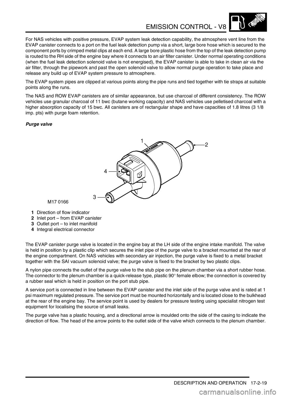
Purge valve
1Direction of flow indicator
2Inlet port – from EVAP canister
3Outlet port – to inlet manifold
4Integral electrical connector
The EVAP canister purge valve is located in the engine bay at the LH side of the engine intake manifold. The valve
is held in position by a plastic clip which secures the inlet pipe of the purge valve to a bracket mounted at the rear of
the engine compartment. On NAS vehicles with secondary air injection, the purge valve is fixed to a metal bracket
together with the SAI vacuum solenoid valve; the purge valve is fixed to the bracket by two plastic clips.
A nylon pipe connects the outlet of the purge valve to the stub pipe on the plenum chamber via a short rubber hose.
The connector to the plenum chamber is a quick-release type, plastic 90
° female elbow; the connection is covered by
a rubber seal which is held in position on the port stub pipe.
A service port is connected in line between the EVAP canister and the inlet side of the purge valve and is rated at 1
psi maximum regulated pressure. The service port must be mounted horizontally and is located close to the bulkhead
at the rear of the engine bay. The service point is used by dealers for pressure testing using specialist nitrogen test
equipment for localising the source of small leaks.
The purge valve has a plastic housing, and a directional arrow is moulded onto the side of the casing to indicate the
direction of flow. The head of the arrow points to the outlet side of the valve which connects to the plenum chamber.
Page 361 of 1672
EMISSION CONTROL - V8
17-2-24 DESCRIPTION AND OPERATION
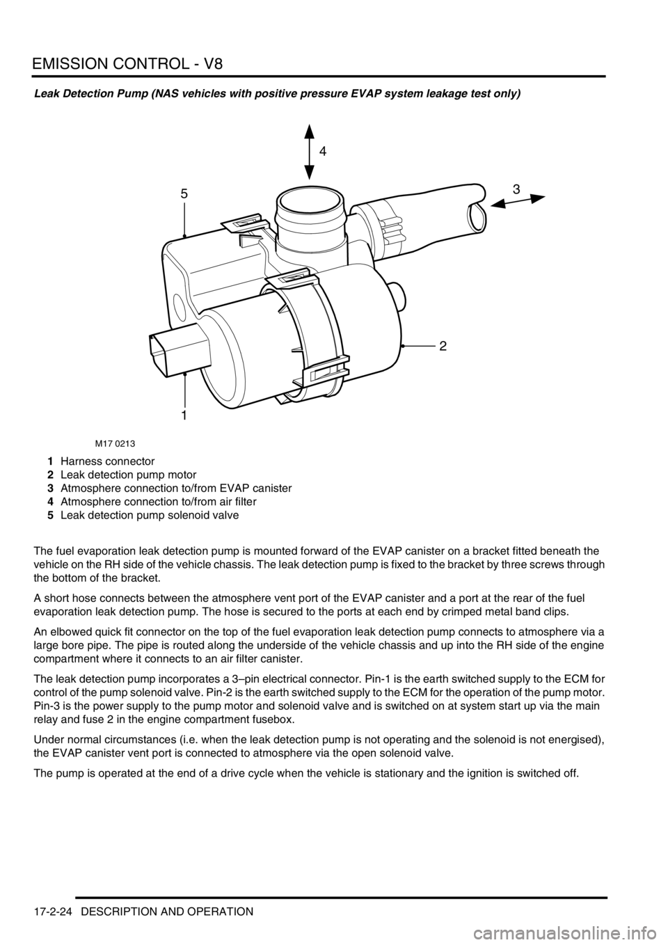
Leak Detection Pump (NAS vehicles with positive pressure EVAP system leakage test only)
1Harness connector
2Leak detection pump motor
3Atmosphere connection to/from EVAP canister
4Atmosphere connection to/from air filter
5Leak detection pump solenoid valve
The fuel evaporation leak detection pump is mounted forward of the EVAP canister on a bracket fitted beneath the
vehicle on the RH side of the vehicle chassis. The leak detection pump is fixed to the bracket by three screws through
the bottom of the bracket.
A short hose connects between the atmosphere vent port of the EVAP canister and a port at the rear of the fuel
evaporation leak detection pump. The hose is secured to the ports at each end by crimped metal band clips.
An elbowed quick fit connector on the top of the fuel evaporation leak detection pump connects to atmosphere via a
large bore pipe. The pipe is routed along the underside of the vehicle chassis and up into the RH side of the engine
compartment where it connects to an air filter canister.
The leak detection pump incorporates a 3–pin electrical connector. Pin-1 is the earth switched supply to the ECM for
control of the pump solenoid valve. Pin-2 is the earth switched supply to the ECM for the operation of the pump motor.
Pin-3 is the power supply to the pump motor and solenoid valve and is switched on at system start up via the main
relay and fuse 2 in the engine compartment fusebox.
Under normal circumstances (i.e. when the leak detection pump is not operating and the solenoid is not energised),
the EVAP canister vent port is connected to atmosphere via the open solenoid valve.
The pump is operated at the end of a drive cycle when the vehicle is stationary and the ignition is switched off.
M17 0213
3
4
5
1
2
Page 362 of 1672
EMISSION CONTROL - V8
DESCRIPTION AND OPERATION 17-2-25
The leak detection pump module contains an integral air by-pass circuit with restrictor (reference-leak orifice) which
is used for providing a reference value for the leak detection test. The restrictor corresponds to an air leak equivalent
to 0.5 mm (0.02 in) diameter. With the solenoid valve open and the purge valve closed, the pump forces pressurised
air through the orifice while the current drawn by the leak detection pump motor is monitored to obtain the reference
value. The orifice must be kept free from contamination, otherwise the reference restriction may appear less than for
a 0.5 mm leak and consequently adversely affect the diagnostic results.
During the leakage test, the solenoid valve is energised, closing the atmosphere vent line between the EVAP canister
and atmosphere and opening a path to the pressurised air supplied from the leak detection pump motor. Air is pumped
into the EVAP system, while the current drawn by the pump motor is monitored. The current drawn during the leakage
test is compared against the value obtained during the reference check, to determine if an EVAP system leak is
present.
The fuel leak detection pump is powered from a 12V supply and operates at a working pressure of 3 kPa.
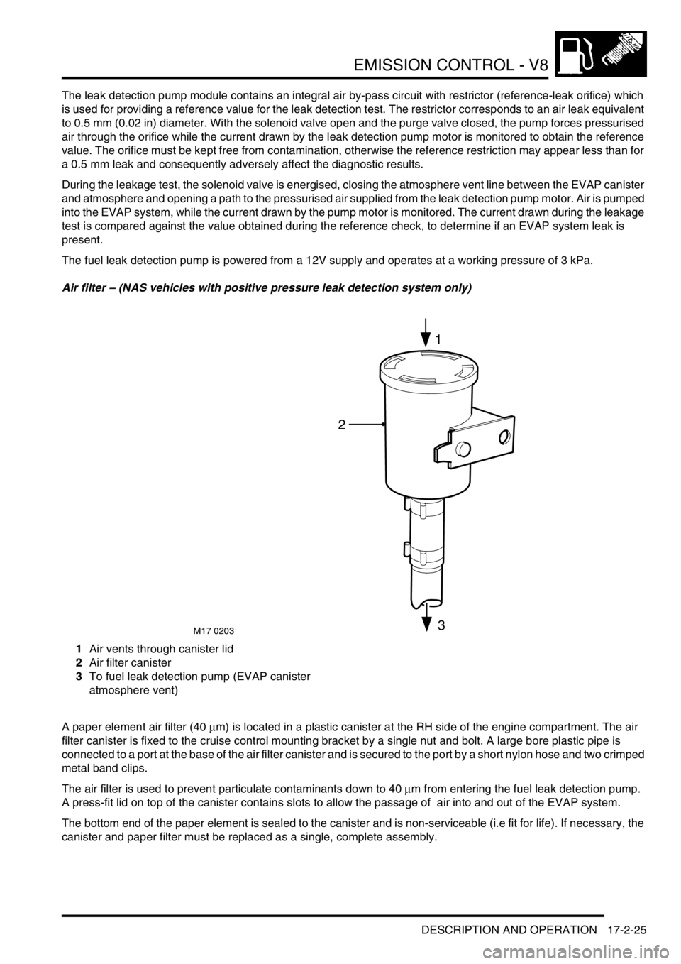
Air filter – (NAS vehicles with positive pressure leak detection system only)
1Air vents through canister lid
2Air filter canister
3To fuel leak detection pump (EVAP canister
atmosphere vent)
A paper element air filter (40
µm) is located in a plastic canister at the RH side of the engine compartment. The air
filter canister is fixed to the cruise control mounting bracket by a single nut and bolt. A large bore plastic pipe is
connected to a port at the base of the air filter canister and is secured to the port by a short nylon hose and two crimped
metal band clips.
The air filter is used to prevent particulate contaminants down to 40
µm from entering the fuel leak detection pump.
A press-fit lid on top of the canister contains slots to allow the passage of air into and out of the EVAP system.
The bottom end of the paper element is sealed to the canister and is non-serviceable (i.e fit for life). If necessary, the
canister and paper filter must be replaced as a single, complete assembly.
M17 0203
2
1
3
Page 364 of 1672
EMISSION CONTROL - V8
DESCRIPTION AND OPERATION 17-2-27
The ECM connector and pins pertinent for secondary air injection are listed in the following table:
Secondary air injection system components
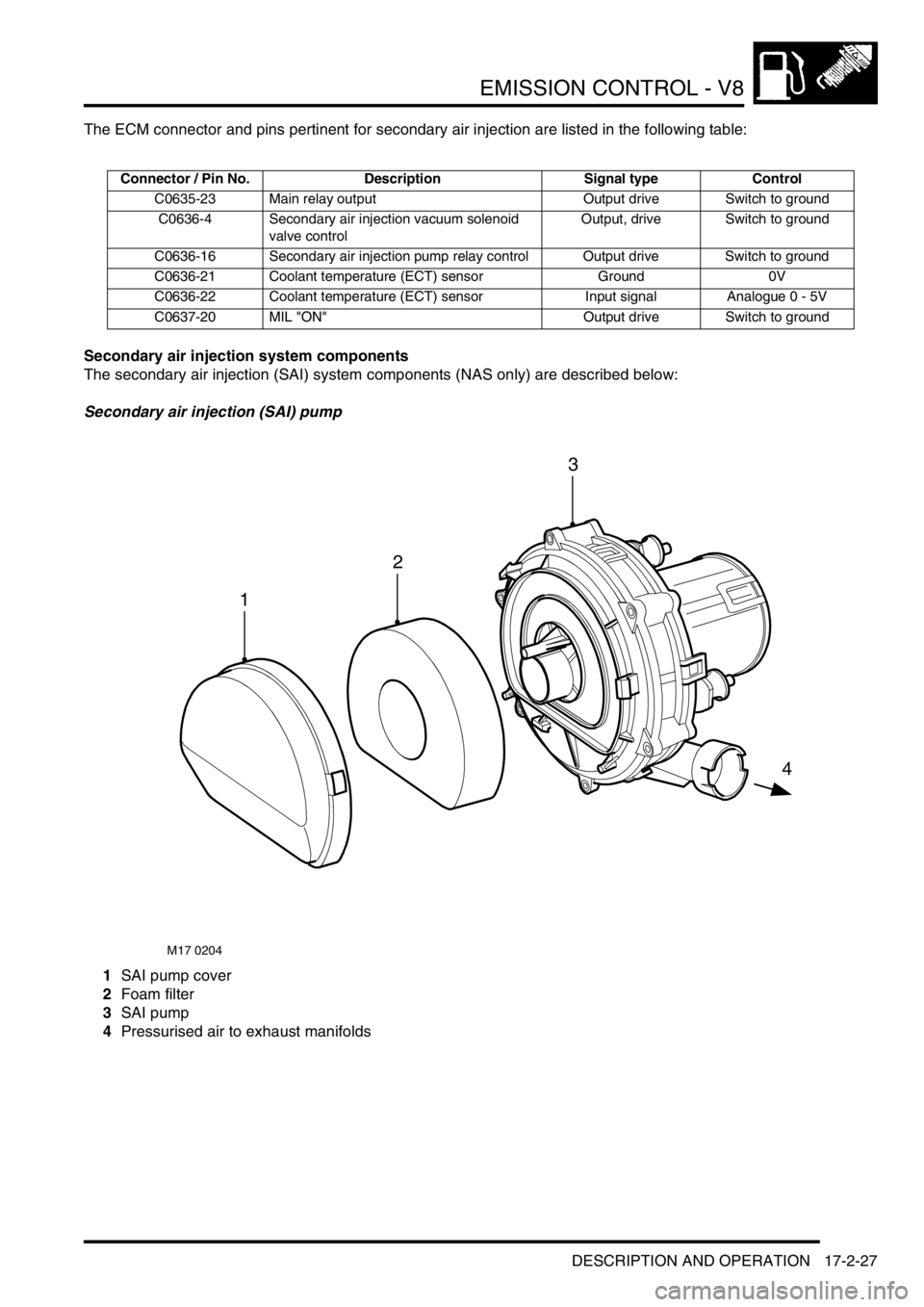
The secondary air injection (SAI) system components (NAS only) are described below:
Secondary air injection (SAI) pump
1SAI pump cover
2Foam filter
3SAI pump
4Pressurised air to exhaust manifolds
Connector / Pin No. Description Signal type Control
C0635-23 Main relay output Output drive Switch to ground
C0636-4 Secondary air injection vacuum solenoid
valve controlOutput, drive Switch to ground
C0636-16 Secondary air injection pump relay control Output drive Switch to ground
C0636-21 Coolant temperature (ECT) sensor Ground 0V
C0636-22 Coolant temperature (ECT) sensor Input signal Analogue 0 - 5V
C0637-20 MIL "ON" Output drive Switch to ground
M17 0204
1
4
2
3
Page 365 of 1672

EMISSION CONTROL - V8
17-2-28 DESCRIPTION AND OPERATION
The SAI pump is attached to a bracket at the rear RH side of the engine compartment and is fixed to the bracket by
three studs and nuts. The pump is electrically powered from a 12V battery supply via a dedicated relay and supplies
approximately 35kg/hr of air when the vehicle is at idle in Neutral/Park on a start from 20
°C (68°F).
Air is drawn into the pump through vents in its front cover and is then passed through a foam filter to remove
particulates before air injection. The air is delivered to the exhaust manifold on each side of the engine through a
combination of plastic and metal pipes.
The air delivery pipe is a flexible plastic type, and is connected to the air pump outlet via a plastic quick-fit connector.
The other end of the flexible plastic pipe connects to the fixed metal pipework via a short rubber hose. The part of the
flexible plastic pipe which is most vulnerable to engine generated heat is protected by heat reflective sleeving. The
metal delivery pipe has a fabricated T-piece included where the pressurised air is split for delivery to each exhaust
manifold via the SAI control valves.
The pipes from the T-piece to each of the SAI control valves are approximately the same length, so that the pressure
and mass of the air delivered to each bank will be equal. The ends of the pipes are connected to the inlet port of each
SAI control valve through short rubber hose connections.
The T-piece is mounted at the rear of the engine (by the ignition coils) and features a welded mounting bracket which
is fixed to the engine by two studs and nuts.
The foam filter in the air intake of the SAI pump provides noise reduction and protects the pump from damage due to
particulate contamination. In addition, the pump is fitted on rubber mountings to help prevent noise which is generated
by pump operation from being transmitted through the vehicle body into the passenger compartment.
If the secondary air injection pump malfunctions, the following fault codes may be stored in the ECM diagnostic
memory, which can be retrieved using 'Testbook':
Secondary air injection (SAI) pump relay
The secondary air injection pump relay is located in the engine compartment fusebox. The engine control module
(ECM) is used to control the operation of the SAI pump via the SAI pump relay. Power to the coil of the relay is supplied
from the vehicle battery via the main relay and the ground connection to the coil is via the ECM.
Power to the SAI pump relay contacts is via fusible link FL2 which is located in the engine compartment fusebox.
P-code Description
P0418Secondary air injection pump powerstage fault (e.g. - SAI pump relay fault / SAI
pump or relay not connected / open circuit / harness damage).
Page 370 of 1672
EMISSION CONTROL - V8
DESCRIPTION AND OPERATION 17-2-33
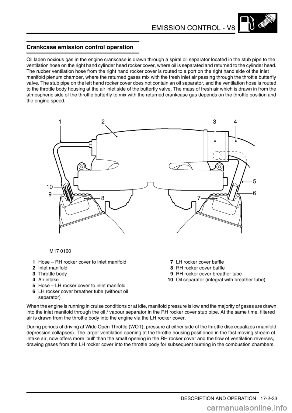
Crankcase emission control operation
Oil laden noxious gas in the engine crankcase is drawn through a spiral oil separator located in the stub pipe to the
ventilation hose on the right hand cylinder head rocker cover, where oil is separated and returned to the cylinder head.
The rubber ventilation hose from the right hand rocker cover is routed to a port on the right hand side of the inlet
manifold plenum chamber, where the returned gases mix with the fresh inlet air passing through the throttle butterfly
valve. The stub pipe on the left hand rocker cover does not contain an oil separator, and the ventilation hose is routed
to the throttle body housing at the air inlet side of the butterfly valve. The mass of fresh air which is drawn in from the
atmospheric side of the throttle butterfly to mix with the returned crankcase gas depends on the throttle position and
the engine speed.
1Hose – RH rocker cover to inlet manifold
2Inlet manifold
3Throttle body
4Air intake
5Hose – LH rocker cover to inlet manifold
6LH rocker cover breather tube (without oil
separator)7LH rocker cover baffle
8RH rocker cover baffle
9RH rocker cover breather tube
10Oil separator (integral with breather tube)
When the engine is running in cruise conditions or at idle, manifold pressure is low and the majority of gases are drawn
into the inlet manifold through the oil / vapour separator in the RH rocker cover stub pipe. At the same time, filtered
air is drawn from the throttle body into the engine via the LH rocker cover.
During periods of driving at Wide Open Throttle (WOT), pressure at either side of the throttle disc equalizes (manifold
depression collapses). The larger ventilation opening at the throttle housing positioned in the fast moving stream of
intake air, now offers more 'pull' than the small opening in the RH rocker cover and the flow of ventilation reverses,
drawing gases from the LH rocker cover into the throttle body for subsequent burning in the combustion chambers.
Page 374 of 1672

EMISSION CONTROL - V8
DESCRIPTION AND OPERATION 17-2-37
In the case of a catalytic converter failure the following failure symptoms may be apparent:
lMIL light on after 2 driving cycles (NAS market only).
lHigh exhaust back pressure if catalyst partly melted.
lExcessive emissions
lStrong smell of H
2S (rotten eggs).
Oxygen sensor voltages can be monitored using 'Testbook', the approximate output voltage from the heated oxygen
sensors with a warm engine at idle and with closed loop fuelling active are shown in the table below:
Mass air flow sensor and air temperature sensor
The engine management ECM uses the mass air flow sensor to measure the mass of air entering the intake and
interprets the data to determine the precise fuel quantity which needs to be injected to maintain the stoichiometric
air:fuel ratio for the exhaust catalysts. If the mass air flow sensor fails, lambda control and idle speed control will be
affected and the emission levels will not be maintained at the optimum level. If the device should fail and the ECM
detects a fault, it invokes a software backup strategy.
+ ENGINE MANAGEMENT SYSTEM - V8, DESCRIPTION AND OPERATION, Description - engine
management.
The air temperature sensor is used by the engine management ECM to monitor the temperature of the inlet air. If the
device fails, catalyst monitoring will be affected. The air temperature sensor in integral to the mass air flow sensor.
+ ENGINE MANAGEMENT SYSTEM - V8, DESCRIPTION AND OPERATION, Description - engine
management.
Throttle position sensor
If the engine management ECM detects a throttle position sensor failure, it may indicate a blocked or restricted air
intake filter. Failure symptoms may include:
lPoor engine running and throttle response
lEmission control failure
lNo closed loop idle speed control
lAltitude adaption is incorrect
If a signal failure should occur, a default value is derived using data from the engine load and speed.
+ ENGINE MANAGEMENT SYSTEM - V8, DESCRIPTION AND OPERATION, Description - engine
management.
Atmospheric pressure will vary with altitude and have a resulting influence on the calculations performed by the ECM
in determining the optimum engine operating conditions to minimise emissions. The following are approximate
atmospheric pressures for the corresponding altitudes:
l0.96 bar at sea level
l0.70 bar at 2,750 m (9,000 ft.)
Measurement Normal catalyst Defective catalyst
Pre-catalytic heated oxygen sensors ~ 100 to 900 mV switching @ ~ 0.5
Hz~ 100 to 900 mV switching @ ~ 0.5 Hz
Post-catalytic heated oxygen sensors ~ 200 to 650 mV, static or slowly
changing~ 200 to 850 mV, changing up to same
frequency as pre-catalytic heated oxygen
sensors
Amplitude ratio (LH HO
2 sensors & RH
HO
2 sensors)<0.3 seconds >0.6 seconds (needs to be approximately
0.75 seconds for single catalyst fault)
Number of speed/load monitoring areas
exceeded (LH & RH)0 >1 (needs to be 3 for fault storage)
Page 378 of 1672
EMISSION CONTROL - V8
DESCRIPTION AND OPERATION 17-2-41
Following the test, the system returns to normal purge operation after the canister vent solenoid opens. Possible
reasons for an EVAP system leak test failure are listed below:
lFuel filler not tightened or cap missing.
lSensor or actuator open circuit.
lShort circuit to vehicle supply or ground.
lEither purge or CVS valve stuck open.
lEither purge or CVS valve stuck shut or blocked pipe.
lPiping broken or not connected.
lLoose or leaking connection.
If the piping is broken forward of the purge valve or is not connected, the engine may run rough and fuelling adaptions
will drift. The fault will not be detected by the leak detection diagnostic, but it will be determined by the engine
management ECM through the fuelling adaption diagnostics.
The evaluation of leakage is dependent on the differential pressure between the fuel tank and ambient atmospheric
pressure, the diagnostic is disabled above altitudes of 9500 ft. (2800 m) to avoid false detection of fuel leaks due to
the change in atmospheric pressure at altitude.
Fuel leak detection system (positive pressure leak detection type) – NAS only
The EVAP system with positive pressure leak detection capability used on NAS vehicles is similar to the standard
system, but also includes a fuel evaporation leak detection pump with integral solenoid valve. It is capable of detecting
holes in the EVAP system down to 0.5 mm (0.02 in.). The test is carried out at the end of a drive cycle, when the
vehicle is stationary and the ignition switch has been turned off. The ECM maintains an earth supply to the Main relay
to hold it on, so that power can be supplied to the leak detection pump.
First a reference measurement is established by passing the pressurised air through a by-pass circuit containing a
fixed sized restriction. The restriction assimilates a 0.5 mm (0.02 in) hole and the current drawn by the pump motor
during this procedure is recorded for comparison against the value to be obtained in the system test. The purge valve
is held closed, and the reversing valve in the leak detection pump module is not energised while the leak detection
pump is switched on. The pressurised air from the leak detection pump is forced through an orifice while the current
drawn by the pump motor is monitored.
Next the EVAP system diagnostic is performed; the solenoid valve is energised so that it closes off the EVAP system's
vent line to atmosphere, and opens a path for the pressurised air from the leak detection pump to be applied to the
closed EVAP system.
The current drawn by the leak detection pump is monitored and checked against that obtained during the reference
measurement. If the current is less than the reference value, this infers there is a hole in the EVAP system greater
than 0.5 mm (0.02 in) which is allowing the positive air pressure to leak out. If the current drawn by the pump motor
is greater than the value obtained during the reference check, the system is sealed and free from leaks. If an EVAP
system leak is detected, the ECM stores the fault in diagnostic memory and the MIL light on the instrument pack is
illuminated.
On NAS vehicles, the ECM works on a 2 trip cycle before illuminating the MIL. On EU-3 vehicles, the ECM works on
a 3 trip cycle before illuminating the MIL.
Following the test, the solenoid valve is opened to normalise the EVAP system pressure and the system returns to
normal purge operation at the start of the next drive cycle. Possible reasons for an EVAP system leak test failure are
listed below:
lFuel filler not tightened or cap missing.
lSensor or actuator open circuit.
lShort circuit to vehicle supply or ground.
lEither purge or solenoid valve stuck open.
lEither purge or solenoid valve stuck shut.
lBlocked pipe or air filter.
lPiping broken or not connected.
lLoose or leaking connection.
If the piping is broken forward of the purge valve or is not connected, the engine may run rough and fuelling adaptions
will drift. The fault will not be detected by the leak detection test, but will be determined by the engine management
ECM through the fuelling adaption diagnostics. This test can be run from TestBook.