air filter LAND ROVER DISCOVERY 2002 Owner's Guide
[x] Cancel search | Manufacturer: LAND ROVER, Model Year: 2002, Model line: DISCOVERY, Model: LAND ROVER DISCOVERY 2002Pages: 1672, PDF Size: 46.1 MB
Page 283 of 1672
ENGINE - V8
12-2-40 REPAIRS
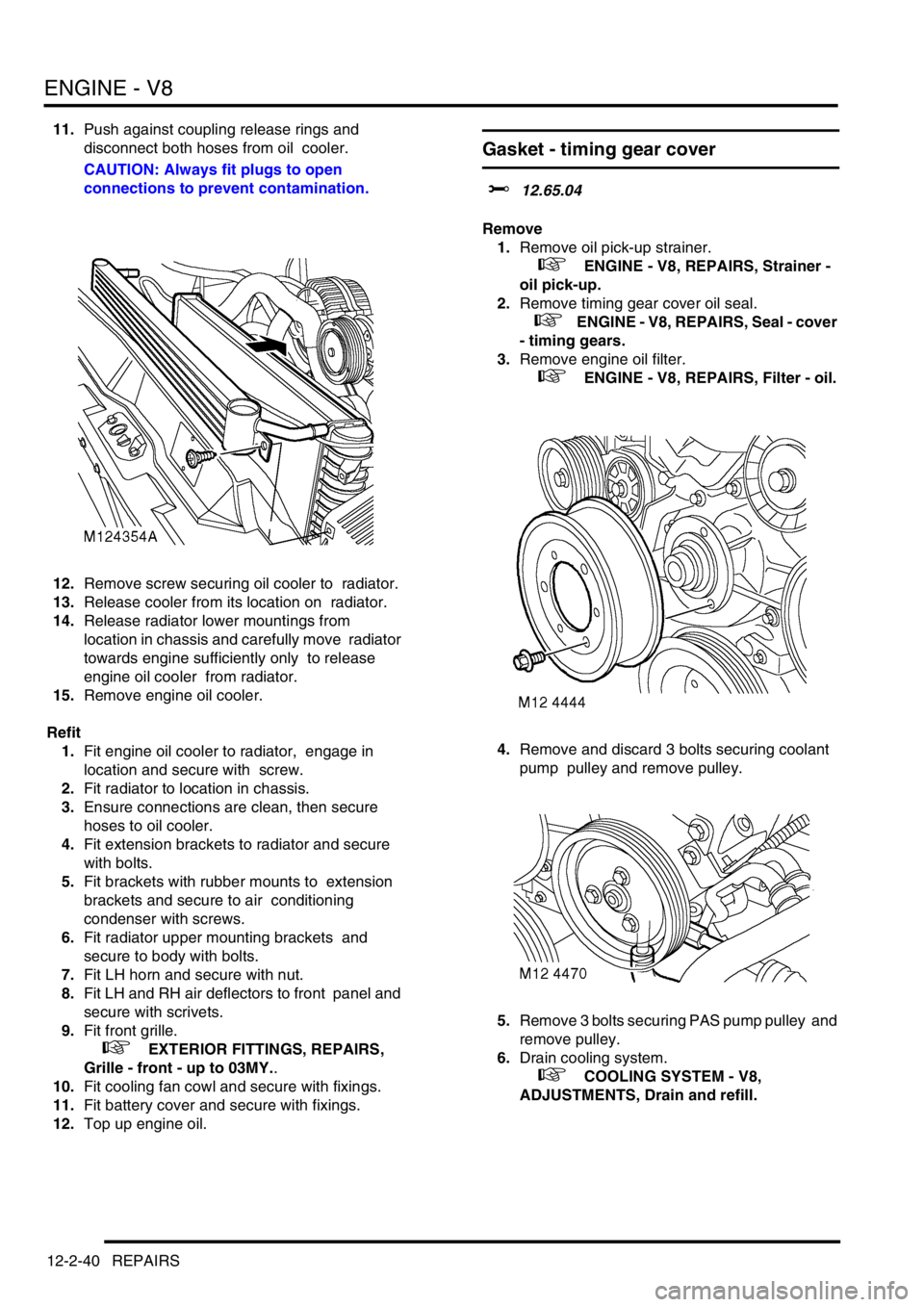
11.Push against coupling release rings and
disconnect both hoses from oil cooler.
CAUTION: Always fit plugs to open
connections to prevent contamination.
12.Remove screw securing oil cooler to radiator.
13.Release cooler from its location on radiator.
14.Release radiator lower mountings from
location in chassis and carefully move radiator
towards engine sufficiently only to release
engine oil cooler from radiator.
15.Remove engine oil cooler.
Refit
1.Fit engine oil cooler to radiator, engage in
location and secure with screw.
2.Fit radiator to location in chassis.
3.Ensure connections are clean, then secure
hoses to oil cooler.
4.Fit extension brackets to radiator and secure
with bolts.
5.Fit brackets with rubber mounts to extension
brackets and secure to air conditioning
condenser with screws.
6.Fit radiator upper mounting brackets and
secure to body with bolts.
7.Fit LH horn and secure with nut.
8.Fit LH and RH air deflectors to front panel and
secure with scrivets.
9.Fit front grille.
+ EXTERIOR FITTINGS, REPAIRS,
Grille - front - up to 03MY..
10.Fit cooling fan cowl and secure with fixings.
11.Fit battery cover and secure with fixings.
12.Top up engine oil.
Gasket - timing gear cover
$% 12.65.04
Remove
1.Remove oil pick-up strainer.
+ ENGINE - V8, REPAIRS, Strainer -
oil pick-up.
2.Remove timing gear cover oil seal.
+ ENGINE - V8, REPAIRS, Seal - cover
- timing gears.
3.Remove engine oil filter.
+ ENGINE - V8, REPAIRS, Filter - oil.
4.Remove and discard 3 bolts securing coolant
pump pulley and remove pulley.
5.Remove 3 bolts securing PAS pump pulley and
remove pulley.
6.Drain cooling system.
+ COOLING SYSTEM - V8,
ADJUSTMENTS, Drain and refill.
Page 285 of 1672
ENGINE - V8
12-2-42 REPAIRS
8.Ensure mating faces of PAS pump pulley and
drive flange are clean, fit pulley and tighten
bolts to 22 Nm (16 lbf.ft).
9.Remove all traces of thread locking material
from coolant pump pulley drive flange bolt
holes using an M8 tap.
10.Ensure mating faces of coolant pump pulley
and drive flange are clean, fit pulley and tighten
new Patchlok bolts to 22 Nm (16 lbf.ft).
11.Ensure mating faces of oil filter and adaptor are
clean, smear clean engine oil onto seal and fit
filter.
12.Fit timing gear cover oil seal.
+ ENGINE - V8, REPAIRS, Seal - cover
- timing gears.
13.Fit oil pick-up strainer.
+ ENGINE - V8, REPAIRS, Strainer -
oil pick-up.
14.Refill cooling system.
+ COOLING SYSTEM - V8,
ADJUSTMENTS, Drain and refill.
Seal - cover - timing gears
$% 12.65.05
Remove
1.Remove auxiliary drive belt.
+ CHARGING AND STARTING,
REPAIRS, Belt - auxiliary drive.
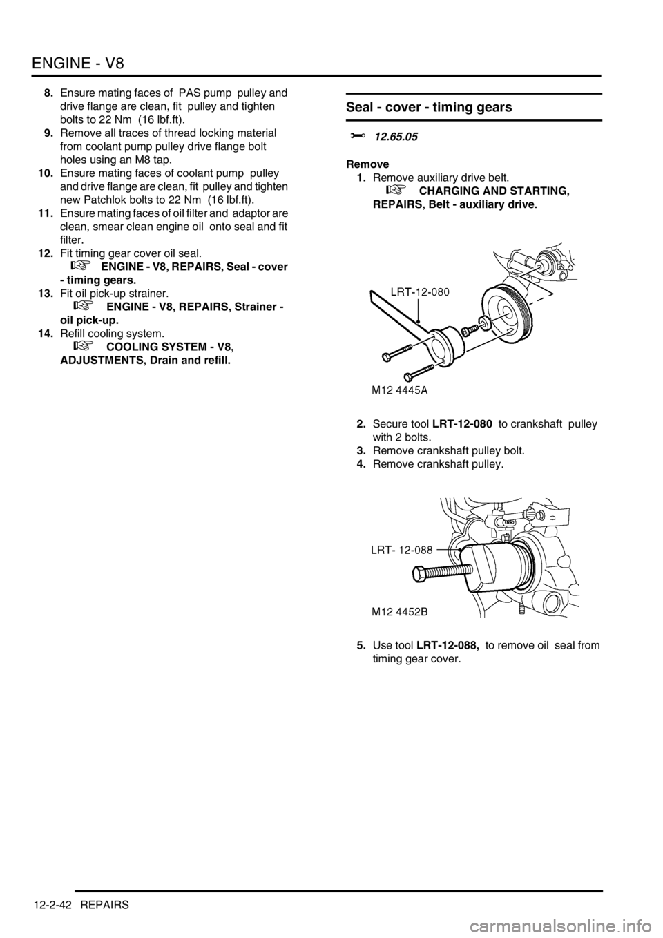
2.Secure tool LRT-12-080 to crankshaft pulley
with 2 bolts.
3.Remove crankshaft pulley bolt.
4.Remove crankshaft pulley.
5.Use tool LRT-12-088, to remove oil seal from
timing gear cover.
Page 322 of 1672
EMISSION CONTROL - TD5
DESCRIPTION AND OPERATION 17-1-1
EMISS ION CONTROL - Td5 DESCRIPTION AND OPERAT ION
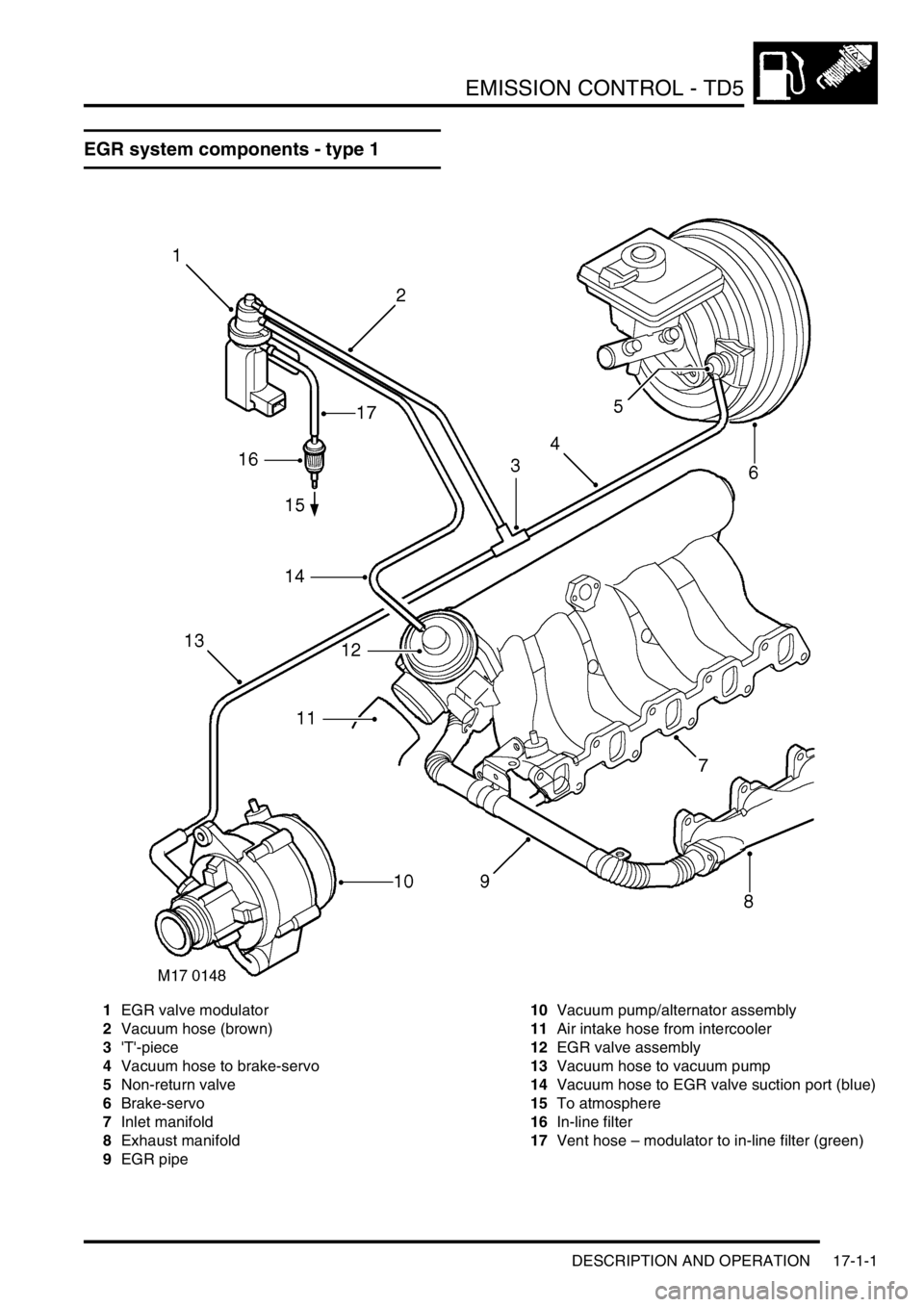
EGR system components - type 1
1EGR valve modulator
2Vacuum hose (brown)
3'T'-piece
4Vacuum hose to brake-servo
5Non-return valve
6Brake-servo
7Inlet manifold
8Exhaust manifold
9EGR pipe10Vacuum pump/alternator assembly
11Air intake hose from intercooler
12EGR valve assembly
13Vacuum hose to vacuum pump
14Vacuum hose to EGR valve suction port (blue)
15To atmosphere
16In-line filter
17Vent hose – modulator to in-line filter (green)
Page 324 of 1672

EMISSION CONTROL - TD5
DESCRIPTION AND OPERATION 17-1-3
1ILT valve modulator
2ILT modulator vacuum hose (brown)
3EGR valve modulator
4EGR modulator vacuum hose (brown)
5Vent hose – EGR modulator to in-line filter
(green)
6Vacuum hose to ILT valve suction port (blue)
7Vacuum hose to EGR valve suction port (blue)
8'T'-piece (4–way)
9Vacuum hose to brake-servo
10Non-return valve
11Brake-servo
12Inlet manifold
13Exhaust manifold
14ILT valve
15EGR cooler - EU3 models
16Vacuum pump / alternator assembly
17Air intake hose from intercooler
18EGR valve (incorporating ILT valve) assembly
19Vacuum hose to vacuum pump
20Vent hose – ILT valve modulator to in-line filter
(green)
213–way connector
22Vent hose - to air cleaner
23ILT modulator harness connector (green)
24EGR modulator harness connector (black)
25To atmosphere - Pre EU3 models
26In-line filter - Pre EU3 models
27EGR pipe - Pre EU3 models
Page 326 of 1672
EMISSION CONTROL - TD5
DESCRIPTION AND OPERATION 17-1-5
Exhaust gas recirculation
The exhaust gas recirculation (EGR) valve permits a controlled amount of exhaust gas to combine with the fresh air
entering the engine. The exhaust gas reduces the combustion temperature by delaying the fuel burning rate, which
assists in reducing the quantity of oxides of nitrogen.
On EU3 models, an EGR cooler is employed to further reduce the combustion temperature. By passing the exhaust
gas through a bundle of pipes flooded by coolant, the density of the exhaust gas going into the engine is increased.
This process further reduces the amount of oxygen, which in turn, further reduces the amount of NO
2 in the exhaust.
Recirculating too much exhaust gas can result in higher emissions of soot, HC and CO due to insufficient air. The
recirculated exhaust gas must be limited so that there is sufficient oxygen available for combustion of the injected fuel
in the combustion chamber, to do this the Engine Control Module (ECM) is used to control the precise quantity of
exhaust gas to be recirculated in accordance with the prevailing operating conditions. Influencing factors include:
lthe mass of air flow detected by the mass air flow sensor.
+ ENGINE MANAGEMENT SYSTEM - Td5, DESCRIPTION AND OPERATION, Description.
lthe ambient air pressure, determined by the ambient air pressure sensor which is used to initiate adjustments
to reduce the amount of smoke produced at high altitudes.
+ ENGINE MANAGEMENT SYSTEM - Td5, DESCRIPTION AND OPERATION, Description.
Other factors which are taken into consideration by the engine management system for determining the optimum
operating condition include:
lManifold inlet air temperature
lCoolant temperature
lEngine speed
lFuel delivered
The main components of the EGR system are as follows.
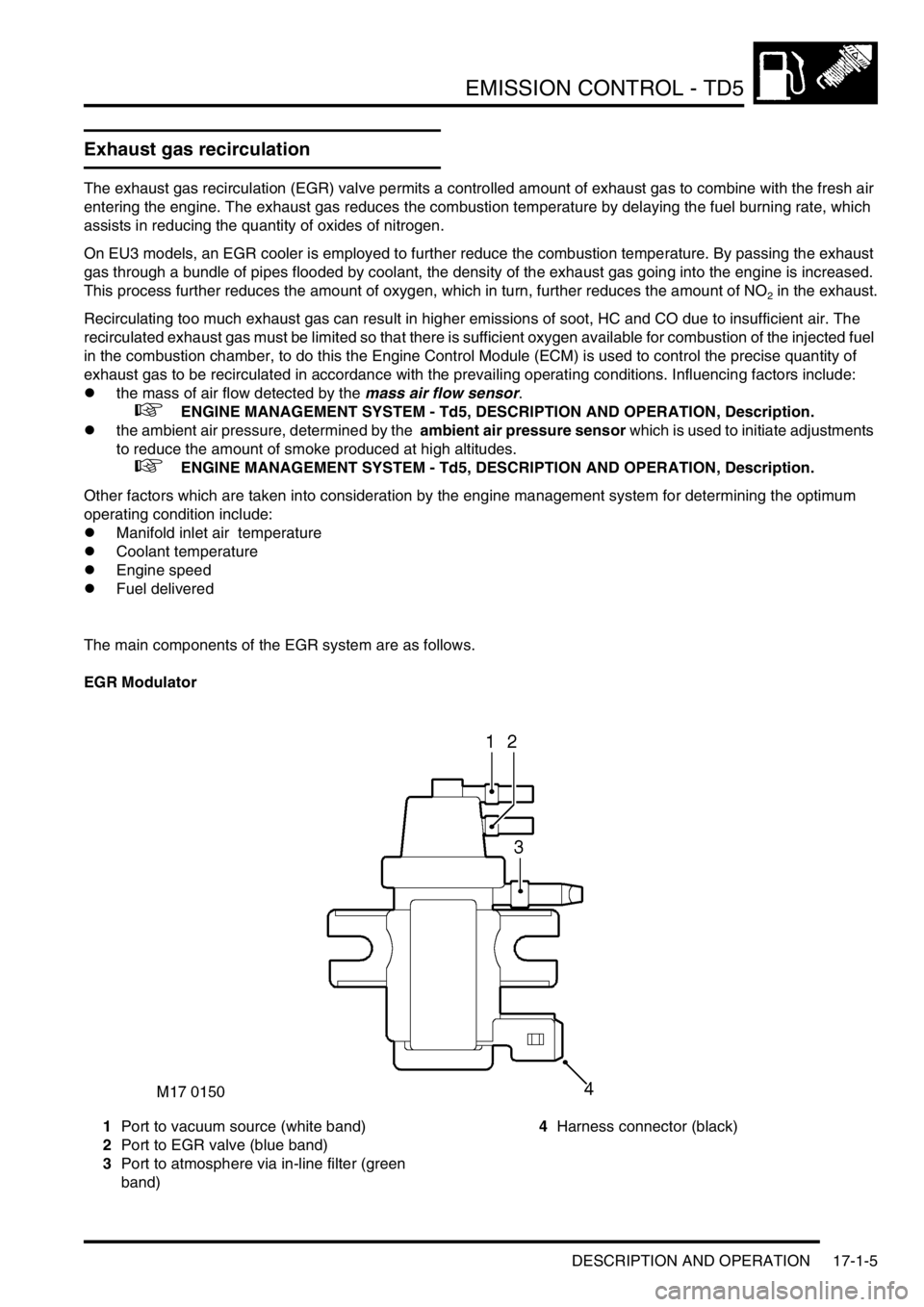
EGR Modulator
1Port to vacuum source (white band)
2Port to EGR valve (blue band)
3Port to atmosphere via in-line filter (green
band)4Harness connector (black)
Page 327 of 1672
EMISSION CONTROL - TD5
17-1-6 DESCRIPTION AND OPERATION
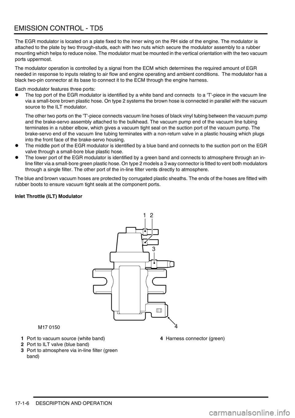
The EGR modulator is located on a plate fixed to the inner wing on the RH side of the engine. The modulator is
attached to the plate by two through-studs, each with two nuts which secure the modulator assembly to a rubber
mounting which helps to reduce noise. The modulator must be mounted in the vertical orientation with the two vacuum
ports uppermost.
The modulator operation is controlled by a signal from the ECM which determines the required amount of EGR
needed in response to inputs relating to air flow and engine operating and ambient conditions. The modulator has a
black two-pin connector at its base to connect it to the ECM through the engine harness.
Each modulator features three ports:
lThe top port of the EGR modulator is identified by a white band and connects to a 'T'-piece in the vacuum line
via a small-bore brown plastic hose. On type 2 systems the brown hose is connected in parallel with the vacuum
source to the ILT modulator.
The other two ports on the 'T'-piece connects vacuum line hoses of black vinyl tubing between the vacuum pump
and the brake-servo assembly attached to the bulkhead. The vacuum pump end of the vacuum line tubing
terminates in a rubber elbow, which gives a vacuum tight seal on the suction port of the vacuum pump. The
brake-servo end of the vacuum line tubing terminates with a non-return valve in a plastic housing which plugs
into the front face of the brake-servo housing.
lThe middle port of the EGR modulator is identified by a blue band and connects to the suction port on the EGR
valve through a small-bore blue plastic hose.
lThe lower port of the EGR modulator is identified by a green band and connects to atmosphere through an in-
line filter via a small-bore green plastic hose. On type 2 models a 3 way connector is fitted to vent both modulators
through a single filter. The other port of the in-line filter vents directly to atmosphere.
The blue and brown vacuum hoses are protected by corrugated plastic sheaths. The ends of the hoses are fitted with
rubber boots to ensure vacuum tight seals at the component ports.
Inlet Throttle (ILT) Modulator
1Port to vacuum source (white band)
2Port to ILT valve (blue band)
3Port to atmosphere via in-line filter (green
band)4Harness connector (green)
Page 328 of 1672
EMISSION CONTROL - TD5
DESCRIPTION AND OPERATION 17-1-7
The ILT modulator is located on a plate fixed to the inner wing on the RH side of the engine below the EGR modulator.
The modulator is attached to the plate by two through-studs, each with two nuts which secure the modulator assembly
to a rubber mounting which helps to reduce noise. The modulator must be mounted in the vertical orientation with the
two vacuum ports uppermost.
The modulator operation is controlled by a signal from the ECM which determines the required ratio of exhaust gas
to fresh inlet air needed in response to inputs relating to air flow and engine operating and ambient conditions. The
modulator has a green two-pin connector at its base to connect it to the ECM through the engine harness.
The ILT valve modulator features three ports:
lThe top port is identified by a white band and connects to a 'T'-piece in the vacuum line via a small-bore brown
plastic hose where it is connected in parallel with the vacuum source line to the EGR valve modulator. The two
other ports on the 'T'-piece connect vacuum line hoses of black vinyl tubing between the vacuum pump attached
to the alternator and the brake-servo assembly attached to the bulkhead.
lThe middle port is identified by a blue band and connects to the suction port on the ILT valve through a small-
bore blue plastic hose.
lThe lower port is identified by a green band and connects to atmosphere through an in-line filter via a green
plastic hose and a three-way connector positioned in-line between the modulators and the filter. The ILT
modulator hose is connected opposite to the two parallel ports at the three-way connector which connect the vent
lines to the EGR valve modulator and the in-line filter. The other port of the in-line filter vents directly to
atmosphere.
The blue and brown vacuum hoses are protected by corrugated plastic sheaths. The ends of the hoses are fitted with
rubber boots to ensure vacuum tight seals at the component ports.
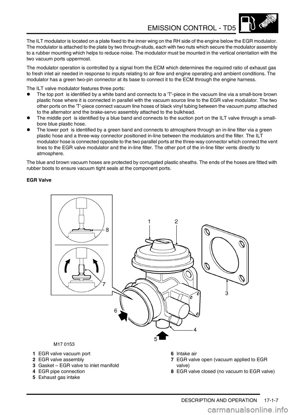
EGR Valve
1EGR valve vacuum port
2EGR valve assembly
3Gasket – EGR valve to inlet manifold
4EGR pipe connection
5Exhaust gas intake6Intake air
7EGR valve open (vacuum applied to EGR
valve)
8EGR valve closed (no vacuum to EGR valve)
Page 330 of 1672

EMISSION CONTROL - TD5
DESCRIPTION AND OPERATION 17-1-9
The ILT valve is used on certain exhaust gas recirculation systems in addition to the standard EGR valve described
above. The ILT valve assembly is mounted at right angles to the EGR valve on the left hand side of the EGR valve
assembly. It is fixed to the EGR valve assembly by three screws.
A vacuum port on top of the ILT valve connects to the ILT modulator though a blue, small-bore suction hose. When
a vacuum is applied to the inlet throttle (ILT) valve suction port, a butterfly valve in the inlet manifold closes via a
spindle and lever mechanism, limiting the supply of fresh intercooled air and creating a depression in the intake
manifold which in turn causes a greater suction at the open port to the EGR delivery pipe. When the vacuum source
is removed from the ILT valve suction port, a spring returns the butterfly to its fully open position. The ILT valve and
EGR valve are operated in conjunction to control the proportional masses of fresh intake air and recirculated exhaust
gas that is allowed to flow through to the inlet manifold.
The EGR valve and ILT valve should be replaced as a single assembly.
In-line air filter - Pre EU3 models
1To modulator vent port
2Filter element
3To atmosphere
The in-line air filter is placed in the ventilation line to the EGR modulator (and the ILT modulator where fitted). The
modulators need to be able to vent to atmosphere in order to release the vacuum supplied to the EGR and ILT valves.
The filter prevents contamination entering the modulators via the vent port which could cause failure; the filter should
be periodically changed in accordance with recommended service intervals. The filter is attached to the rear side of
the mounting plate used to hold the vacuum modulators at the inner wing on the RH side of the engine. The filter is
held in position by a clamping bracket which is attached to the mounting plate through a nut and bolt. The filter must
be mounted in the vertical position.
Note: EU3 models are not fitted with an in-line filter, the ventilation line connects directly to the air cleaner housing,
where it vents to atmosphere.
Page 341 of 1672

EMISSION CONTROL - V8
17-2-4 DESCRIPTION AND OPERATION
Evaporative emission system (with
positive pressure leak detection)
component layout (NAS only)
1Purge valve
2Service port
3Air filter canister
4EVAP canister breather tube
5Leak detection pump
6EVAP canister
7Vent pipe – fuel tank to EVAP canister
8Liquid vapour separator (metal)9Fuel filler cap
10Fuel filler
11Fuel tank breather assembly
12Vent hose
13Roll over valves (inside fuel tank)
14Fuel tank
15Purge line connection to engine manifold
M17 0208
3
1
7
4
14
11
6
8
10
13
12
15
2
5
9
Page 346 of 1672
EMISSION CONTROL - V8
DESCRIPTION AND OPERATION 17-2-9
Emission Control Systems
Engine design has evolved in order to minimise the emission of harmful by-products. Emission control systems are
fitted to Land Rover vehicles which are designed to maintain the emission levels within the legal limits pertaining for
the specified market.
Despite the utilisation of specialised emission control equipment, it is still necessary to ensure that the engine is
correctly maintained and is in good mechanical order so that it operates at its optimal condition. In particular, ignition
timing has an effect on the production of HC and NO
x emissions, with the harmful emissions rising as the ignition
timing is advanced.
CAUTION: In many countries it is against the law for a vehicle owner or an unauthorised dealer to modify or
tamper with emission control equipment. In some cases, the vehicle owner and/or the dealer may even be
liable for prosecution.
The engine management ECM is fundamental for controlling the emission control systems. In addition to controlling
normal operation, the system complies with On Board Diagnostic (OBD) system strategies. The system monitors and
reports on faults detected with ignition, fuelling and exhaust systems which cause an excessive increase in tailpipe
emissions. This includes component failures, engine misfire, catalyst damage, catalyst efficiency, fuel evaporative
loss and exhaust leaks.
When an emission relevant fault is determined, the fault condition is stored in the ECM memory. For NAS vehicles,
the MIL warning light on the instrument pack will be illuminated when the fault is confirmed. Confirmation of a fault
condition occurs if the fault is still found to be present during the driving cycle subsequent to the one when the fault
was first detected.
+ ENGINE MANAGEMENT SYSTEM - V8, DESCRIPTION AND OPERATION, Description - engine
management.
The following types of supplementary control system are used to reduce harmful emissions released into the
atmosphere from the vehicle:
1Crankcase emission control – also known as blow-by gas emissions from the engine crankcase.
2Exhaust emission control – to limit the undesirable by-products of combustion.
3Fuel vapour evaporative loss control – to restrict the emission of fuel through evaporation from the fuel
system.
4Fuel leak detection system (NAS only) – there are two types of system which may be used to check the
evaporative emission system for the presence of leaks from the fuel tank to purge valve.
aVacuum leak detection test – checks for leaks down to 1 mm (0.04 in.) in diameter.
bPositive pressure leak detection test – utilises a leak detection pump to check for leaks down to 0.5 mm (0.02
in.) in diameter.
5Secondary air injection system (NAS only) – to reduce emissions experienced during cold starting.
Crankcase emission control system
The concentration of hydrocarbons in the crankcase of an engine is much greater than that in the vehicle's exhaust
system. In order to prevent the emission of these hydrocarbons into the atmosphere, crankcase emission control
systems are employed and are a standard legal requirement.
The crankcase ventilation system is an integral part of the air supply to the engine combustion chambers and it is
often overlooked when diagnosing problems associated with engine performance. A blocked ventilation pipe or filter
or excessive air leak into the inlet system through a damaged pipe or a leaking gasket can affect the air:fuel mixture,
performance and efficiency of the engine. Periodically check the ventilation hoses are not cracked and that they are
securely fitted to form airtight connections at their relevant ports.
The purpose of the crankcase ventilation system is to ensure that any noxious gas generated in the engine crankcase
is rendered harmless by complete burning of the fuel in the combustion chamber. Burning the crankcase vapours in
a controlled manner decreases the HC pollutants that could be emitted and helps to prevent the development of
sludge in the engine oil as well as increasing fuel economy.