LAND ROVER DISCOVERY 2002 Workshop Manual
Manufacturer: LAND ROVER, Model Year: 2002, Model line: DISCOVERY, Model: LAND ROVER DISCOVERY 2002Pages: 1672, PDF Size: 46.1 MB
Page 311 of 1672
ENGINE - V8
12-2-68 OVERHAUL
Inspect
1.Clean carbon from piston. Inspect piston for
distortion, cracks and burning.
2.Remove piston rings from piston.
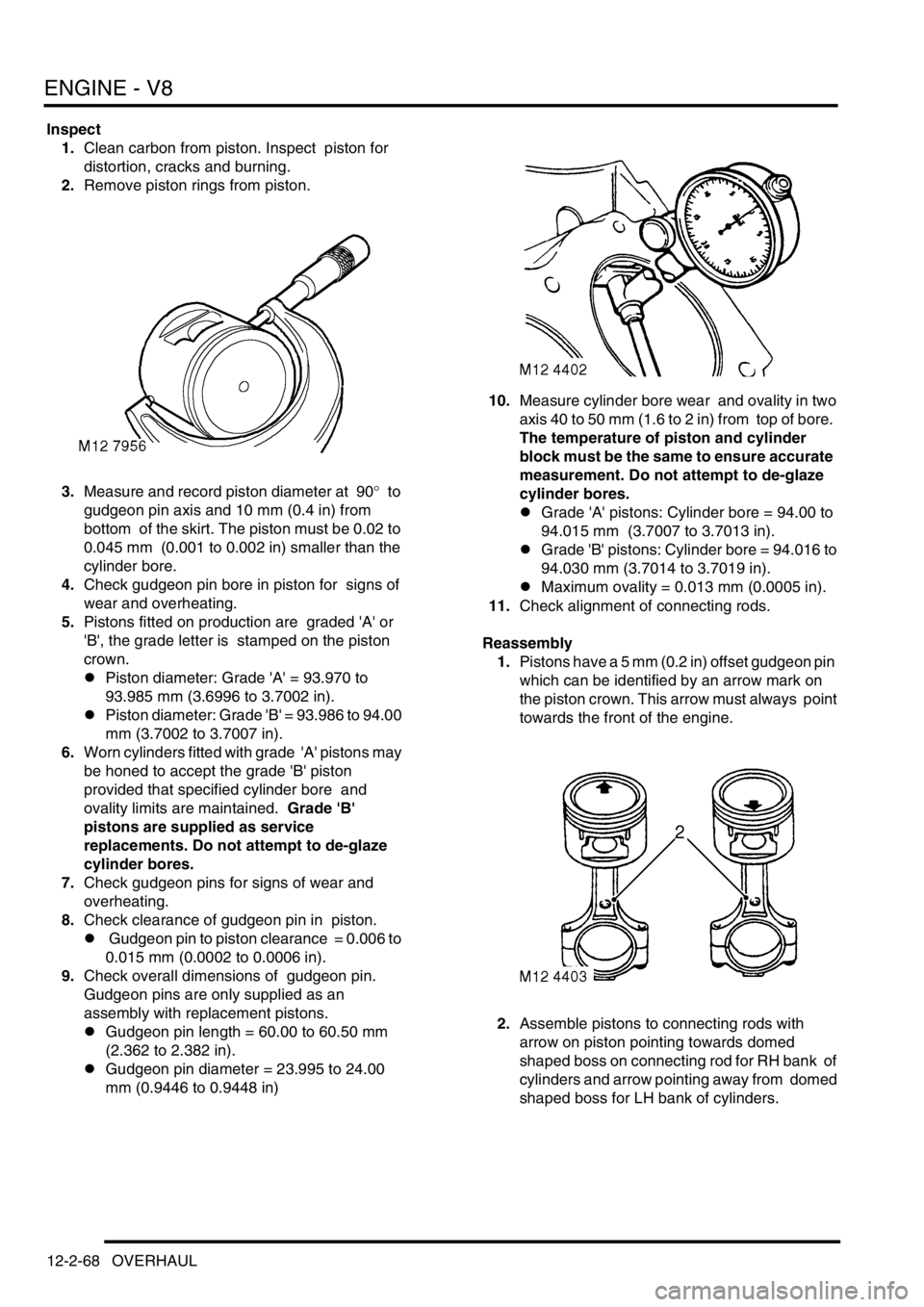
3.Measure and record piston diameter at 90
° to
gudgeon pin axis and 10 mm (0.4 in) from
bottom of the skirt. The piston must be 0.02 to
0.045 mm (0.001 to 0.002 in) smaller than the
cylinder bore.
4.Check gudgeon pin bore in piston for signs of
wear and overheating.
5.Pistons fitted on production are graded 'A' or
'B', the grade letter is stamped on the piston
crown.
lPiston diameter: Grade 'A' = 93.970 to
93.985 mm (3.6996 to 3.7002 in).
lPiston diameter: Grade 'B' = 93.986 to 94.00
mm (3.7002 to 3.7007 in).
6.Worn cylinders fitted with grade 'A' pistons may
be honed to accept the grade 'B' piston
provided that specified cylinder bore and
ovality limits are maintained. Grade 'B'
pistons are supplied as service
replacements. Do not attempt to de-glaze
cylinder bores.
7.Check gudgeon pins for signs of wear and
overheating.
8.Check clearance of gudgeon pin in piston.
l Gudgeon pin to piston clearance = 0.006 to
0.015 mm (0.0002 to 0.0006 in).
9.Check overall dimensions of gudgeon pin.
Gudgeon pins are only supplied as an
assembly with replacement pistons.
lGudgeon pin length = 60.00 to 60.50 mm
(2.362 to 2.382 in).
lGudgeon pin diameter = 23.995 to 24.00
mm (0.9446 to 0.9448 in)10.Measure cylinder bore wear and ovality in two
axis 40 to 50 mm (1.6 to 2 in) from top of bore.
The temperature of piston and cylinder
block must be the same to ensure accurate
measurement. Do not attempt to de-glaze
cylinder bores.
lGrade 'A' pistons: Cylinder bore = 94.00 to
94.015 mm (3.7007 to 3.7013 in).
lGrade 'B' pistons: Cylinder bore = 94.016 to
94.030 mm (3.7014 to 3.7019 in).
lMaximum ovality = 0.013 mm (0.0005 in).
11.Check alignment of connecting rods.
Reassembly
1.Pistons have a 5 mm (0.2 in) offset gudgeon pin
which can be identified by an arrow mark on
the piston crown. This arrow must always point
towards the front of the engine.
2.Assemble pistons to connecting rods with
arrow on piston pointing towards domed
shaped boss on connecting rod for RH bank of
cylinders and arrow pointing away from domed
shaped boss for LH bank of cylinders.
Page 312 of 1672
ENGINE - V8
OVERHAUL 12-2-69
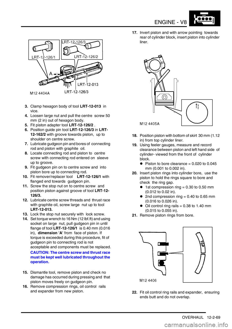
3.Clamp hexagon body of tool LRT-12-013 in
vice.
4.Loosen large nut and pull the centre screw 50
mm (2 in) out of hexagon body.
5.Fit piston adapter tool LRT-12-126/2 .
6.Position guide pin tool LRT-12-126/3 in LRT-
12-162/2 with groove towards piston, up to
shoulder on centre screw.
7.Lubricate gudgeon pin and bores of connecting
rod and piston with graphite oil.
8.Locate connecting rod and piston to centre
screw with connecting rod entered on sleeve
up to groove.
9.Fit gudgeon pin on to centre screw and into
piston bore up to connecting rod.
10.Fit remover/replacer tool LRT-12-126/1 with
flanged end towards gudgeon pin.
11.Screw the stop nut on to centre screw and
position piston against groove of tool LRT-12-
126/3.
12.Lubricate centre screw threads and thrust race
with graphite oil, screw large nut up to tool
LRT-12-013.
13.Lock the stop nut securely with lock screw.
14.Set torque wrench to 16 Nm (12 lbf.ft) and using
socket on large nut, pull gudgeon pin in until
flange of tool LRT-12-126/1 is 0.40 mm (0.016
in), dimension 'A' from face of piston. If
torque is exceeded during this procedure, fit of
gudgeon pin to connecting rod is not
acceptable and components must be replaced.
CAUTION: The centre screw and thrust race
must be kept well lubricated throughout the
operation.
15.Dismantle tool, remove piston and check no
damage has occurred during pressing and that
piston moves freely on gudgeon pin.
16.Remove compression rings, oil control rails
and expander from new piston. 17.Invert piston and with arrow pointing towards
rear of cylinder block, insert piston into cylinder
liner.
18.Position piston with bottom of skirt 30 mm (1.12
in) from top cylinder liner.
19.Using feeler gauges, measure and record
clearance between piston and left hand side of
cylinder- viewed from the front of cylinder
block.
lPiston to bore clearance = 0.020 to 0.045
mm (0.001 to 0.002 in).
20.Insert piston rings into cylinder bore, use the
piston to hold the rings square to bore and
check the ring gap.
l1st compression ring = 0.30 to 0.50 mm
(0.012 to 0.02 in).
l2nd compression ring = 0.40 to 0.65 mm
(0.016 to 0.026 in).
lOil control ring rails = 0.38 to 1.40 mm
(0.015 to 0.055 in).
21.Remove piston rings from bore.
22.Fit oil control ring rails and expander, ensuring
ends butt and do not overlap.
Page 313 of 1672
ENGINE - V8
12-2-70 OVERHAUL
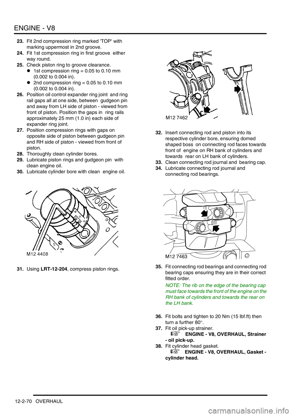
23.Fit 2nd compression ring marked 'TOP' with
marking uppermost in 2nd groove.
24.Fit 1st compression ring in first groove either
way round.
25.Check piston ring to groove clearance.
l1st compression ring = 0.05 to 0.10 mm
(0.002 to 0.004 in).
l2nd compression ring = 0.05 to 0.10 mm
(0.002 to 0.004 in).
26.Position oil control expander ring joint and ring
rail gaps all at one side, between gudgeon pin
and away from LH side of piston - viewed from
front of piston. Position the gaps in ring rails
approximately 25 mm (1.0 in) each side of
expander ring joint.
27.Position compression rings with gaps on
opposite side of piston between gudgeon pin
and RH side of piston - viewed from front of
piston.
28.Thoroughly clean cylinder bores.
29.Lubricate piston rings and gudgeon pin with
clean engine oil.
30.Lubricate cylinder bore with clean engine oil.
31.Using LRT-12-204, compress piston rings. 32.Insert connecting rod and piston into its
respective cylinder bore, ensuring domed
shaped boss on connecting rod faces towards
front of engine on RH bank of cylinders and
towards rear on LH bank of cylinders.
33.Clean connecting rod journal and bearing cap.
34.Lubricate connecting rod journal and
connecting rod bearings.
35.Fit connecting rod bearings and connecting rod
bearing caps ensuring they are in their correct
fitted order.
NOTE: The rib on the edge of the bearing cap
must face towards the front of the engine on the
RH bank of cylinders and towards the rear on
the LH bank.
36.Fit bolts and tighten to 20 Nm (15 lbf.ft) then
turn a further 80
°.
37.Fit oil pick-up strainer.
+ ENGINE - V8, OVERHAUL, Strainer
- oil pick-up.
38.Fit cylinder head gasket.
+ ENGINE - V8, OVERHAUL, Gasket -
cylinder head.
Page 314 of 1672
ENGINE - V8
OVERHAUL 12-2-71
Bearings - connecting rods
$% 12.17.16.01
Disassembly
1.Remove oil pick up strainer.
+ ENGINE - V8, OVERHAUL, Strainer
- oil pick-up.
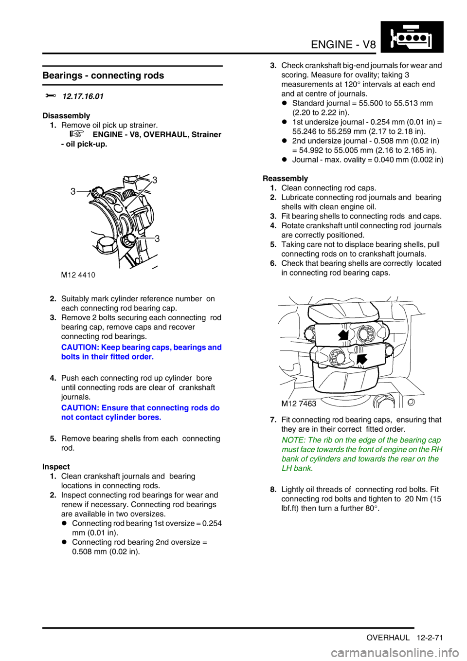
2.Suitably mark cylinder reference number on
each connecting rod bearing cap.
3.Remove 2 bolts securing each connecting rod
bearing cap, remove caps and recover
connecting rod bearings.
CAUTION: Keep bearing caps, bearings and
bolts in their fitted order.
4.Push each connecting rod up cylinder bore
until connecting rods are clear of crankshaft
journals.
CAUTION: Ensure that connecting rods do
not contact cylinder bores.
5.Remove bearing shells from each connecting
rod.
Inspect
1.Clean crankshaft journals and bearing
locations in connecting rods.
2.Inspect connecting rod bearings for wear and
renew if necessary. Connecting rod bearings
are available in two oversizes.
lConnecting rod bearing 1st oversize = 0.254
mm (0.01 in).
lConnecting rod bearing 2nd oversize =
0.508 mm (0.02 in).3.Check crankshaft big-end journals for wear and
scoring. Measure for ovality; taking 3
measurements at 120
° intervals at each end
and at centre of journals.
lStandard journal = 55.500 to 55.513 mm
(2.20 to 2.22 in).
l1st undersize journal - 0.254 mm (0.01 in) =
55.246 to 55.259 mm (2.17 to 2.18 in).
l2nd undersize journal - 0.508 mm (0.02 in)
= 54.992 to 55.005 mm (2.16 to 2.165 in).
lJournal - max. ovality = 0.040 mm (0.002 in)
Reassembly
1.Clean connecting rod caps.
2.Lubricate connecting rod journals and bearing
shells with clean engine oil.
3.Fit bearing shells to connecting rods and caps.
4.Rotate crankshaft until connecting rod journals
are correctly positioned.
5.Taking care not to displace bearing shells, pull
connecting rods on to crankshaft journals.
6.Check that bearing shells are correctly located
in connecting rod bearing caps.
7.Fit connecting rod bearing caps, ensuring that
they are in their correct fitted order.
NOTE: The rib on the edge of the bearing cap
must face towards the front of engine on the RH
bank of cylinders and towards the rear on the
LH bank.
8.Lightly oil threads of connecting rod bolts. Fit
connecting rod bolts and tighten to 20 Nm (15
lbf.ft) then turn a further 80
°.
Page 315 of 1672
ENGINE - V8
12-2-72 OVERHAUL
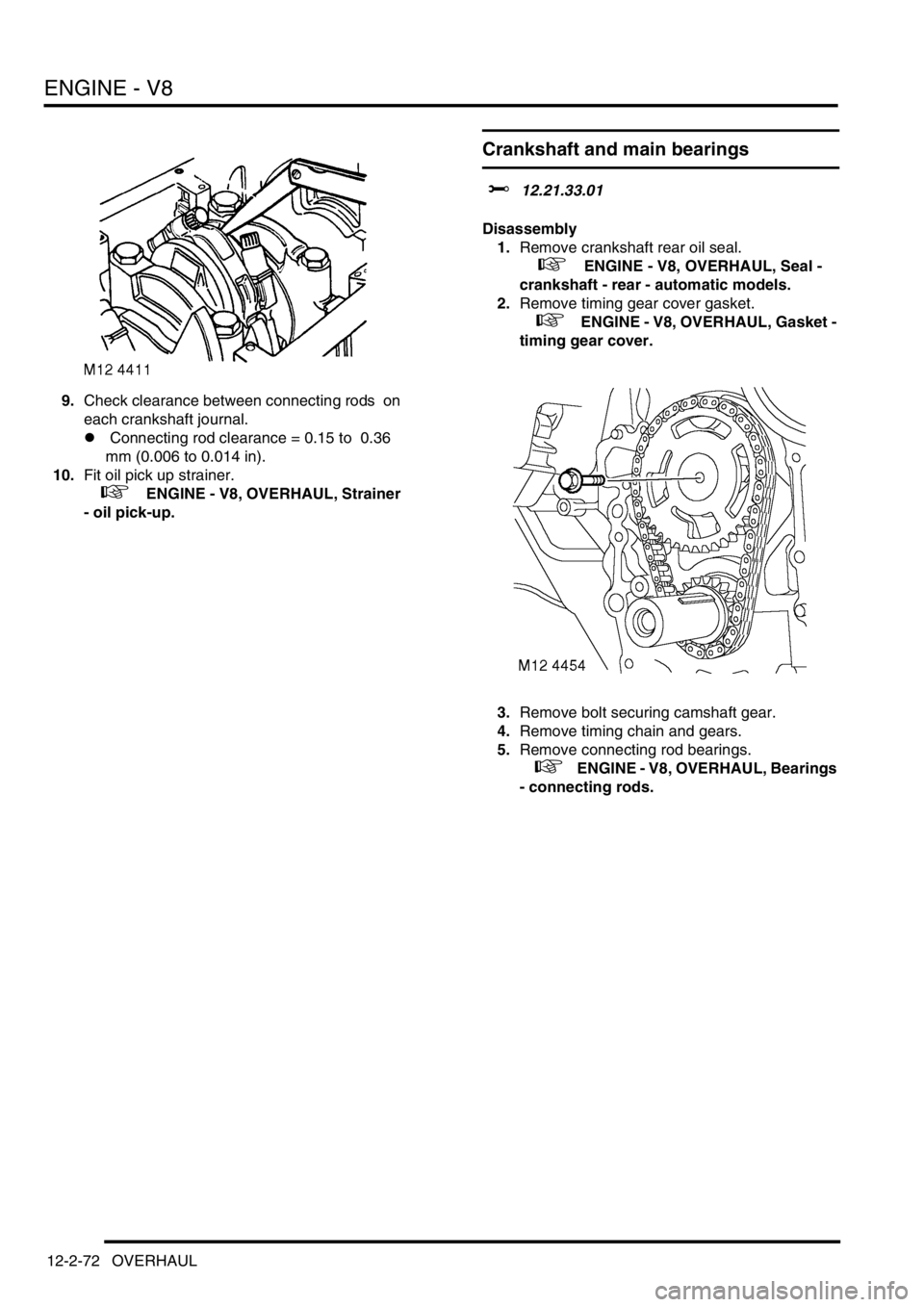
9.Check clearance between connecting rods on
each crankshaft journal.
l Connecting rod clearance = 0.15 to 0.36
mm (0.006 to 0.014 in).
10.Fit oil pick up strainer.
+ ENGINE - V8, OVERHAUL, Strainer
- oil pick-up.
Crankshaft and main bearings
$% 12.21.33.01
Disassembly
1.Remove crankshaft rear oil seal.
+ ENGINE - V8, OVERHAUL, Seal -
crankshaft - rear - automatic models.
2.Remove timing gear cover gasket.
+ ENGINE - V8, OVERHAUL, Gasket -
timing gear cover.
3.Remove bolt securing camshaft gear.
4.Remove timing chain and gears.
5.Remove connecting rod bearings.
+ ENGINE - V8, OVERHAUL, Bearings
- connecting rods.
Page 316 of 1672
ENGINE - V8
OVERHAUL 12-2-73
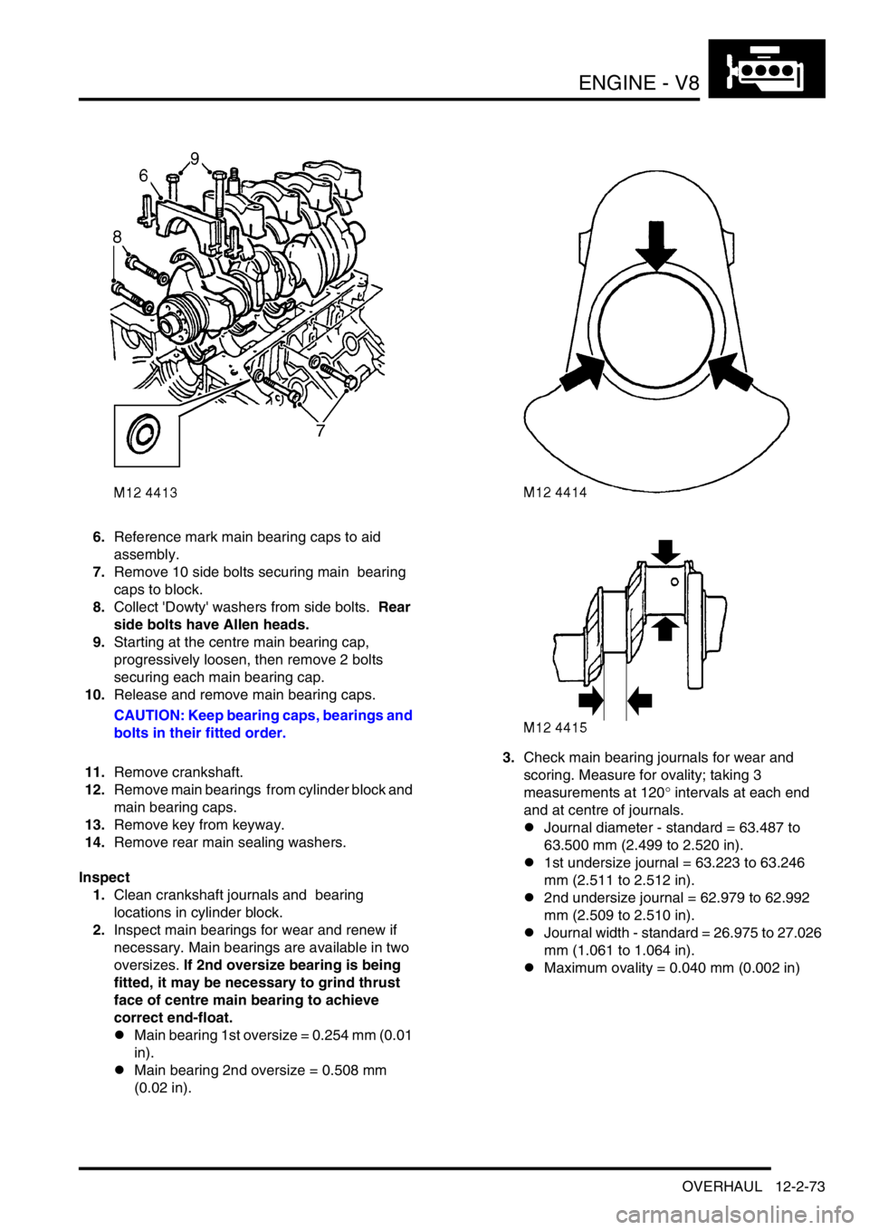
6.Reference mark main bearing caps to aid
assembly.
7.Remove 10 side bolts securing main bearing
caps to block.
8.Collect 'Dowty' washers from side bolts. Rear
side bolts have Allen heads.
9.Starting at the centre main bearing cap,
progressively loosen, then remove 2 bolts
securing each main bearing cap.
10.Release and remove main bearing caps.
CAUTION: Keep bearing caps, bearings and
bolts in their fitted order.
11.Remove crankshaft.
12.Remove main bearings from cylinder block and
main bearing caps.
13.Remove key from keyway.
14.Remove rear main sealing washers.
Inspect
1.Clean crankshaft journals and bearing
locations in cylinder block.
2.Inspect main bearings for wear and renew if
necessary. Main bearings are available in two
oversizes. If 2nd oversize bearing is being
fitted, it may be necessary to grind thrust
face of centre main bearing to achieve
correct end-float.
lMain bearing 1st oversize = 0.254 mm (0.01
in).
lMain bearing 2nd oversize = 0.508 mm
(0.02 in).3.Check main bearing journals for wear and
scoring. Measure for ovality; taking 3
measurements at 120
° intervals at each end
and at centre of journals.
lJournal diameter - standard = 63.487 to
63.500 mm (2.499 to 2.520 in).
l1st undersize journal = 63.223 to 63.246
mm (2.511 to 2.512 in).
l2nd undersize journal = 62.979 to 62.992
mm (2.509 to 2.510 in).
lJournal width - standard = 26.975 to 27.026
mm (1.061 to 1.064 in).
lMaximum ovality = 0.040 mm (0.002 in)
Page 317 of 1672
ENGINE - V8
12-2-74 OVERHAUL
Reassembly
1.Clean main bearing locations in cylinder block
and bearing caps.
2.Clean sealant from rear main bearing cap and
mating faces.
3.Fit key to keyway.
4.Check threads of main bearing cap bolts for
damage, renew bolts in pairs.
5.Lubricate grooved main bearing shells with
clean engine oil and fit to their locations in
cylinder block.
NOTE: Ensure that the flanged bearing is fitted
to the centre position.
6.Lubricate crankshaft journals with clean engine
oil.
7.Position crankshaft in cylinder block.
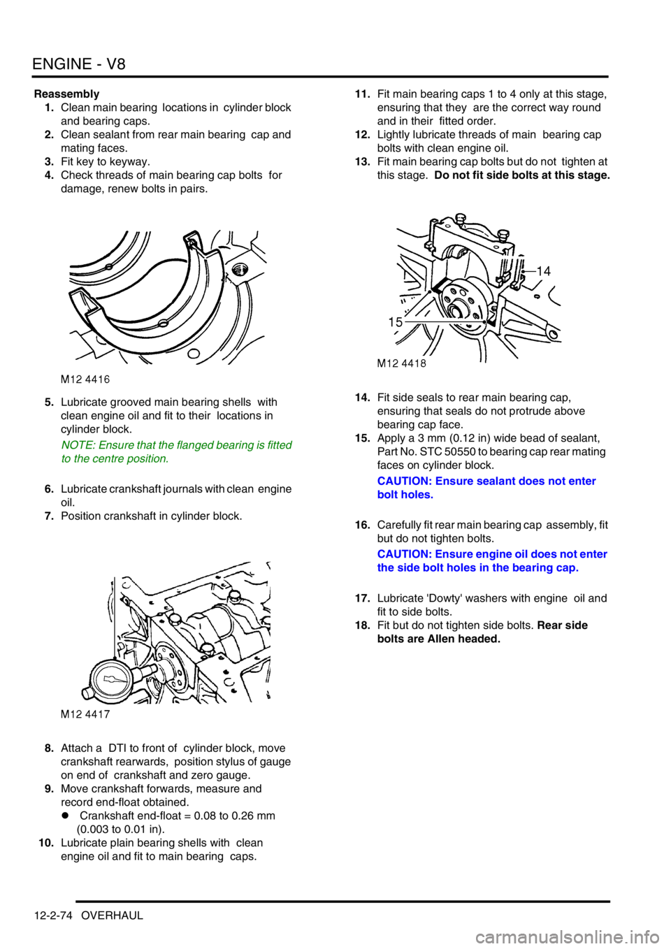
8.Attach a DTI to front of cylinder block, move
crankshaft rearwards, position stylus of gauge
on end of crankshaft and zero gauge.
9.Move crankshaft forwards, measure and
record end-float obtained.
l Crankshaft end-float = 0.08 to 0.26 mm
(0.003 to 0.01 in).
10.Lubricate plain bearing shells with clean
engine oil and fit to main bearing caps. 11.Fit main bearing caps 1 to 4 only at this stage,
ensuring that they are the correct way round
and in their fitted order.
12.Lightly lubricate threads of main bearing cap
bolts with clean engine oil.
13.Fit main bearing cap bolts but do not tighten at
this stage. Do not fit side bolts at this stage.
14.Fit side seals to rear main bearing cap,
ensuring that seals do not protrude above
bearing cap face.
15.Apply a 3 mm (0.12 in) wide bead of sealant,
Part No. STC 50550 to bearing cap rear mating
faces on cylinder block.
CAUTION: Ensure sealant does not enter
bolt holes.
16.Carefully fit rear main bearing cap assembly, fit
but do not tighten bolts.
CAUTION: Ensure engine oil does not enter
the side bolt holes in the bearing cap.
17.Lubricate 'Dowty' washers with engine oil and
fit to side bolts.
18.Fit but do not tighten side bolts. Rear side
bolts are Allen headed.
Page 318 of 1672
ENGINE - V8
OVERHAUL 12-2-75
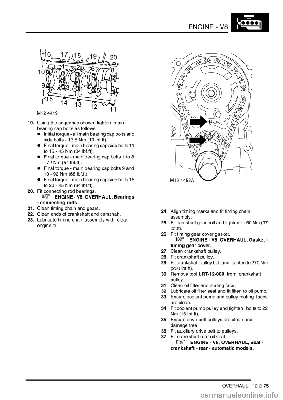
19.Using the sequence shown, tighten main
bearing cap bolts as follows:
lInitial torque - all main bearing cap bolts and
side bolts - 13.5 Nm (10 lbf.ft).
lFinal torque - main bearing cap side bolts 11
to 15 - 45 Nm (34 lbf.ft).
lFinal torque - main bearing cap bolts 1 to 8
- 72 Nm (54 lbf.ft).
lFinal torque - main bearing cap bolts 9 and
10 - 92 Nm (68 lbf.ft).
lFinal torque - main bearing cap side bolts 16
to 20 - 45 Nm (34 lbf.ft).
20.Fit connecting rod bearings.
+ ENGINE - V8, OVERHAUL, Bearings
- connecting rods.
21.Clean timing chain and gears.
22.Clean ends of crankshaft and camshaft.
23.Lubricate timing chain assembly with clean
engine oil. 24.Align timing marks and fit timing chain
assembly.
25.Fit camshaft gear bolt and tighten to 50 Nm (37
lbf.ft).
26.Fit timing gear cover gasket.
+ ENGINE - V8, OVERHAUL, Gasket -
timing gear cover.
27.Clean crankshaft pulley.
28.Fit crankshaft pulley.
29.Fit crankshaft pulley bolt and tighten to 270 Nm
(200 lbf.ft).
30.Remove tool LRT-12-080 from crankshaft
pulley.
31.Clean oil filter and mating face.
32.Lubricate oil filter seal and fit filter to oil pump.
33.Ensure coolant pump and pulley mating faces
are clean.
34.Fit coolant pump pulley and tighten bolts to 22
Nm (16 lbf.ft).
35.Ensure drive belt pulleys are clean and
damage free.
36.Fit auxiliary drive belt to pulleys.
37.Fit crankshaft rear oil seal.
+ ENGINE - V8, OVERHAUL, Seal -
crankshaft - rear - automatic models.
Page 319 of 1672
ENGINE - V8
12-2-76 OVERHAUL
Camshaft
$% 12.13.02.01
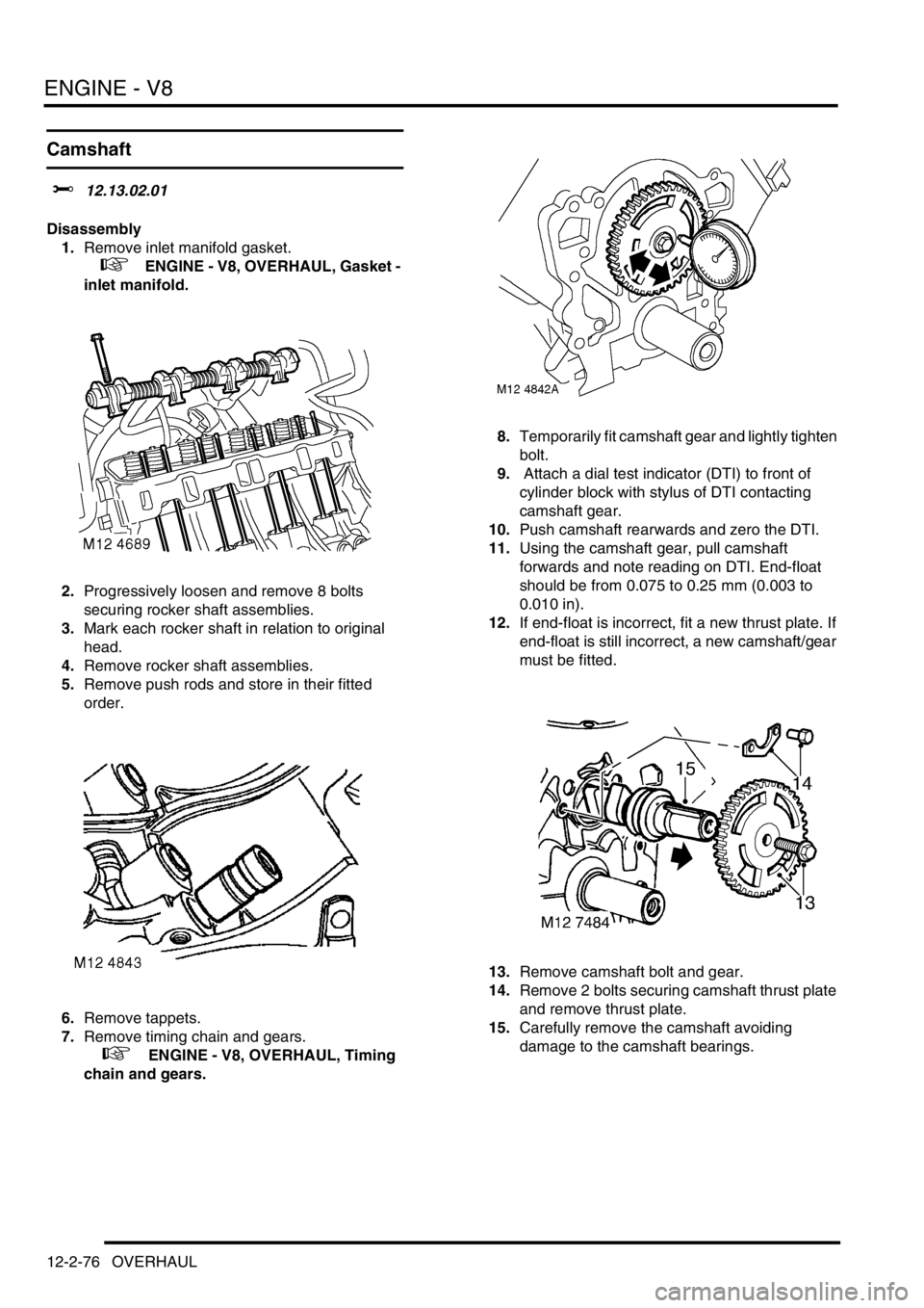
Disassembly
1.Remove inlet manifold gasket.
+ ENGINE - V8, OVERHAUL, Gasket -
inlet manifold.
2.Progressively loosen and remove 8 bolts
securing rocker shaft assemblies.
3.Mark each rocker shaft in relation to original
head.
4.Remove rocker shaft assemblies.
5.Remove push rods and store in their fitted
order.
6.Remove tappets.
7.Remove timing chain and gears.
+ ENGINE - V8, OVERHAUL, Timing
chain and gears.8.Temporarily fit camshaft gear and lightly tighten
bolt.
9. Attach a dial test indicator (DTI) to front of
cylinder block with stylus of DTI contacting
camshaft gear.
10.Push camshaft rearwards and zero the DTI.
11.Using the camshaft gear, pull camshaft
forwards and note reading on DTI. End-float
should be from 0.075 to 0.25 mm (0.003 to
0.010 in).
12.If end-float is incorrect, fit a new thrust plate. If
end-float is still incorrect, a new camshaft/gear
must be fitted.
13.Remove camshaft bolt and gear.
14.Remove 2 bolts securing camshaft thrust plate
and remove thrust plate.
15.Carefully remove the camshaft avoiding
damage to the camshaft bearings.
Page 320 of 1672

ENGINE - V8
OVERHAUL 12-2-77
Reassembly
1.Clean camshaft bearings in block.
2.Clean camshaft.
3.Wipe camshaft bearing faces and lobes.
4.Clean thrust plate and mating face.
5.Lubricate camshaft bearings with clean engine
oil.
6.Fit camshaft, take care not to damage camshaft
bearings.
7.Lubricate thrust plate and mating face with
clean engine oil.
8.Position thrust plate, fit and tighten bolts to 22
Nm (17 lbf.ft).
9.Fit timing chain and gears.
+ ENGINE - V8, OVERHAUL, Timing
chain and gears.
10.Immerse tappets in engine oil. Before fitting,
pump the inner sleeve of tappet several times
using a push rod to prime the tappets.
11.Clean tappet bores.
12.Lubricate tappets and tappet bores with clean
engine oil.
13.Fit tappets.
14.Clean push rods.
15.Lubricate tappet end of push rods with clean
engine oil.
16.Fit push rods.
17.Clean bases of rocker pillars and mating faces.
18.Clean contact surfaces on rockers and valves.
19.Lubricate contact surfaces on rockers and
valves with clean engine oil.
20.Fit rocker shafts and engage push rods. Ensure
rockers shafts are fitted to the correct cylinder
head.
21.Fit and progressively tighten rocker shaft bolts
to 40 Nm (30 lbf.ft).
22.Fit inlet manifold gasket.
+ ENGINE - V8, OVERHAUL, Gasket -
inlet manifold.