air filter LAND ROVER DISCOVERY 2002 Manual PDF
[x] Cancel search | Manufacturer: LAND ROVER, Model Year: 2002, Model line: DISCOVERY, Model: LAND ROVER DISCOVERY 2002Pages: 1672, PDF Size: 46.1 MB
Page 554 of 1672

FUEL DELIVERY SYSTEM - TD5
DESCRIPTION AND OPERATION 19-1-9
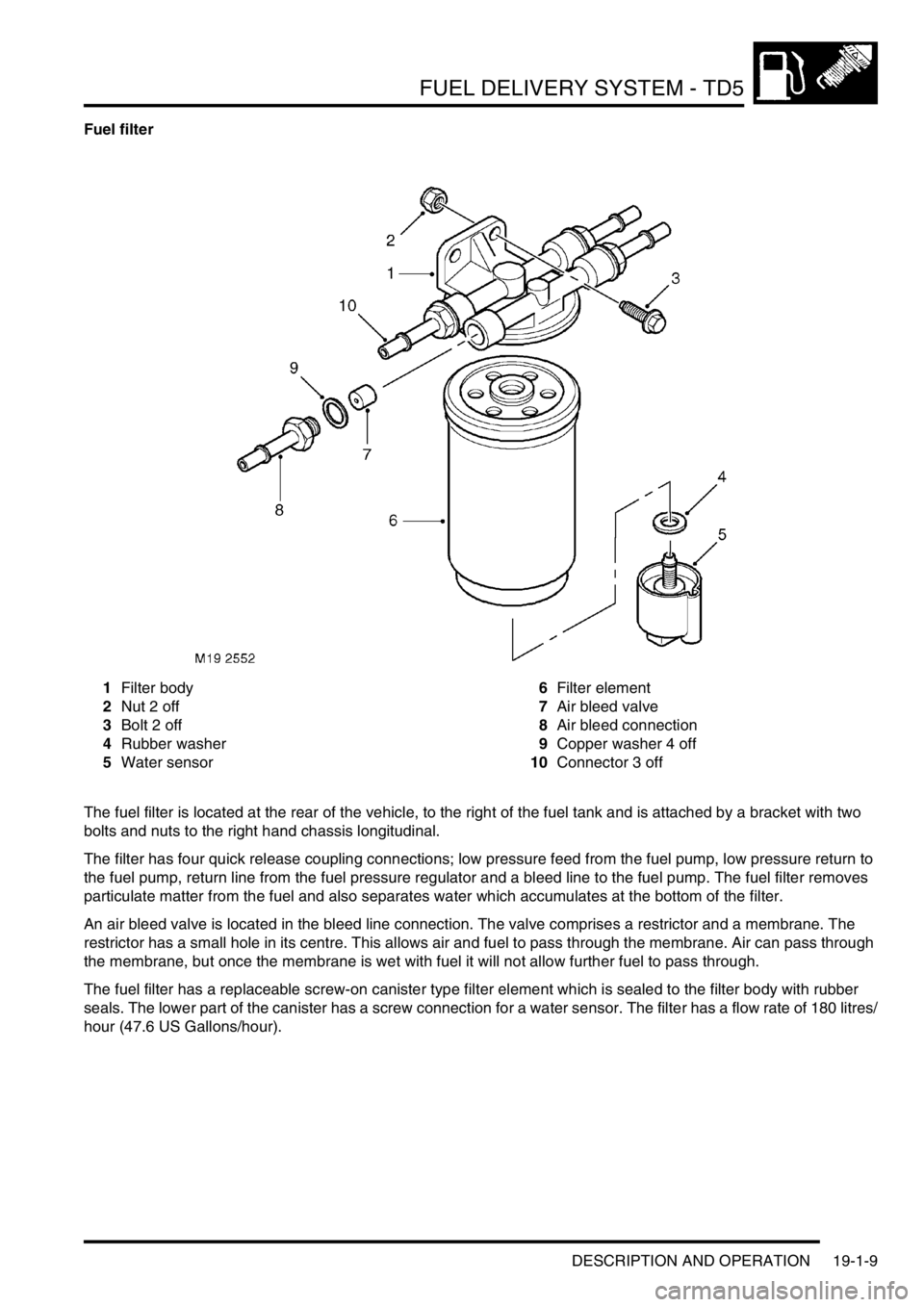
Fuel filter
1Filter body
2Nut 2 off
3Bolt 2 off
4Rubber washer
5Water sensor6Filter element
7Air bleed valve
8Air bleed connection
9Copper washer 4 off
10Connector 3 off
The fuel filter is located at the rear of the vehicle, to the right of the fuel tank and is attached by a bracket with two
bolts and nuts to the right hand chassis longitudinal.
The filter has four quick release coupling connections; low pressure feed from the fuel pump, low pressure return to
the fuel pump, return line from the fuel pressure regulator and a bleed line to the fuel pump. The fuel filter removes
particulate matter from the fuel and also separates water which accumulates at the bottom of the filter.
An air bleed valve is located in the bleed line connection. The valve comprises a restrictor and a membrane. The
restrictor has a small hole in its centre. This allows air and fuel to pass through the membrane. Air can pass through
the membrane, but once the membrane is wet with fuel it will not allow further fuel to pass through.
The fuel filter has a replaceable screw-on canister type filter element which is sealed to the filter body with rubber
seals. The lower part of the canister has a screw connection for a water sensor. The filter has a flow rate of 180 litres/
hour (47.6 US Gallons/hour).
Page 574 of 1672

FUEL DELIVERY SYSTEM - V8
DESCRIPTION AND OPERATION 19-2-9
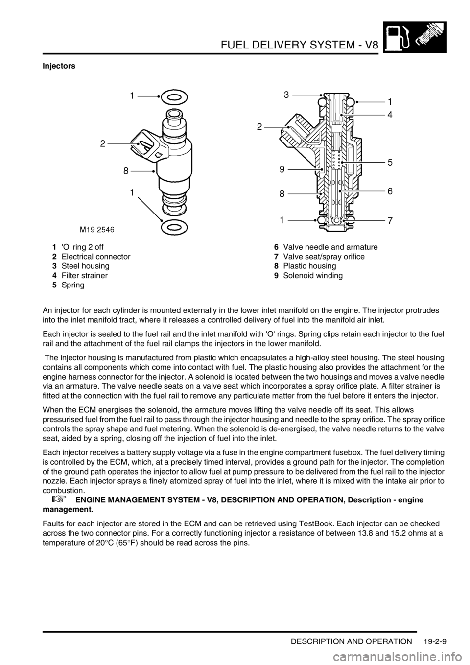
Injectors
1'O' ring 2 off
2Electrical connector
3Steel housing
4Filter strainer
5Spring6Valve needle and armature
7Valve seat/spray orifice
8Plastic housing
9Solenoid winding
An injector for each cylinder is mounted externally in the lower inlet manifold on the engine. The injector protrudes
into the inlet manifold tract, where it releases a controlled delivery of fuel into the manifold air inlet.
Each injector is sealed to the fuel rail and the inlet manifold with 'O' rings. Spring clips retain each injector to the fuel
rail and the attachment of the fuel rail clamps the injectors in the lower manifold.
The injector housing is manufactured from plastic which encapsulates a high-alloy steel housing. The steel housing
contains all components which come into contact with fuel. The plastic housing also provides the attachment for the
engine harness connector for the injector. A solenoid is located between the two housings and moves a valve needle
via an armature. The valve needle seats on a valve seat which incorporates a spray orifice plate. A filter strainer is
fitted at the connection with the fuel rail to remove any particulate matter from the fuel before it enters the injector.
When the ECM energises the solenoid, the armature moves lifting the valve needle off its seat. This allows
pressurised fuel from the fuel rail to pass through the injector housing and needle to the spray orifice. The spray orifice
controls the spray shape and fuel metering. When the solenoid is de-energised, the valve needle returns to the valve
seat, aided by a spring, closing off the injection of fuel into the inlet.
Each injector receives a battery supply voltage via a fuse in the engine compartment fusebox. The fuel delivery timing
is controlled by the ECM, which, at a precisely timed interval, provides a ground path for the injector. The completion
of the ground path operates the injector to allow fuel at pump pressure to be delivered from the fuel rail to the injector
nozzle. Each injector sprays a finely atomized spray of fuel into the inlet, where it is mixed with the intake air prior to
combustion.
+ ENGINE MANAGEMENT SYSTEM - V8, DESCRIPTION AND OPERATION, Description - engine
management.
Faults for each injector are stored in the ECM and can be retrieved using TestBook. Each injector can be checked
across the two connector pins. For a correctly functioning injector a resistance of between 13.8 and 15.2 ohms at a
temperature of 20
°C (65°F) should be read across the pins.
Page 590 of 1672

COOLING SYSTEM - TD5
DESCRIPTION AND OPERATION 26-1-7
Pipes and hoses
The coolant circuit comprises flexible hoses and metal formed pipes which direct the coolant into and out of the
engine, radiator and heater matrix. Plastic pipes are used for the bleed and overflow pipes to the expansion tank.
A bleed screw is installed in the radiator top hose and is used to bleed air during system filling. A drain plug to drain
the heater and cylinder block circuit of coolant is located on the underside of the coolant pump feed pipe.
Oil cooler
The oil cooler is located on the left hand side of the engine block behind the oil centrifuge and oil filter. Oil from the oil
pump is passed through a heat exchanger which is surrounded by coolant in a housing on the side of the engine.
Full water pump flow is directed along the cooler housing which also distributes the flow evenly along the block into
three core holes for cylinder cooling. This cools the engine oil before it is passed into the engine. A small percentage
of the coolant from the oil cooler passes into a metal pipe behind the engine. It then flows into the lower radiator via
a hose.
Fuel cooler
The fuel cooler is located on the right hand side of the engine and is attached to the inlet manifold. The cooler is
cylindrical in design and has a coolant feed connection at its forward end. A 'T' connection at the rear of the cooler
provides a connection for the coolant return from the heater matrix and coolant return from the fuel cooler.
The 'T' connection houses a thermostat which opens at approximately 82
°C. This prevents the cooler operating in
cold climates.
Two quick release couplings on the cooler allow for the connection of the fuel feed from the pressure regulator and
return to the fuel tank. A counter flow system is used within the cooler.
Fuel flows around a coolant jacket within the cooler and flows from the back to the front of the cooler. As the hot fuel
cools travelling slowly forwards it meets progressively colder coolant travelling in the opposite direction maintaining a
differential cooling effect.
EGR Cooler
The EGR Cooler is mounted on the front of the cylinder head. Coolant from the oil cooler flows around the EGR cooler,
cooling the exhaust gas, to improve exhaust emissions, before being returned to the expansion tank.
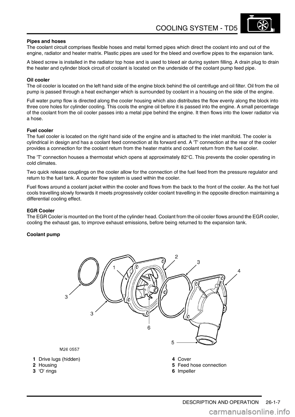
Coolant pump
1Drive lugs (hidden)
2Housing
3'O' rings4Cover
5Feed hose connection
6Impeller
Page 842 of 1672

AUTOMATIC GEARBOX - ZF4HP22 - 24
REPAIRS 44-45
Filter - oil
$% 44.24.07
Remove
1.Remove oil sump gasket.
+ AUTOMATIC GEARBOX - ZF4HP22
- 24, REPAIRS, Gasket - oil sump.
2.Remove Torx screw securing oil pick-up tube
and remove tube.
3.Remove 2 Torx screws securing filter to valve
body and discard 'O' rings.
Refit
1.Clean filter and pick-up tube using a lint free
cloth.
2.Fit new 'O' rings to filter.
3.Position filter and tighten Torx screws to 8 Nm
(6 lbf.ft).
4.Position oil pick-up tube and tighten Torx
screw to 8 Nm (6 lbf.ft).
5.Fit oil sump gasket.
+ AUTOMATIC GEARBOX - ZF4HP22
- 24, REPAIRS, Gasket - oil sump.
Cooler - fluid - Td5
$% 44.24.10
Remove
1.Remove intercooler.
+ ENGINE MANAGEMENT SYSTEM -
Td5, REPAIRS, Intercooler.
2.Disconnect fluid temperature sensor multiplug.
3.Position absorbent cloth under each gearbox
cooler hose connection to collect spillage.
4.Push against coupling release ring and
disconnect both fluid hoses from cooler.
5.Remove screw and release cooler from
radiator.
6.Carefully remove cooler.
Page 844 of 1672

AUTOMATIC GEARBOX - ZF4HP22 - 24
REPAIRS 44-47
7.Remove temperature sensor and discard
sealing washer.
Refit
1.Use new sealing washer and tighten
temperature sensor to 14 Nm (10 lbf.ft).
2.Fit cooler, engage with radiator and secure with
screw.
3.Connect temperature sensor multiplug.
4.Ensure connections are clean and fit hoses to
cooler.
5. If fitted:Fit engine oil cooler.
+ ENGINE - V8, REPAIRS, Cooler -
engine oil.
6.Check and if necessary top up gearbox fluid.
Valve body assembly
$% 44.40.01
Remove
1.Remove gearbox oil filter.
+ AUTOMATIC GEARBOX - ZF4HP22
- 24, REPAIRS, Filter - oil.
2.Remove 2 bolts securing speed sensor
harness bracket to valve body.
3.Disconnect multiplug from gearbox housing.
4.Using a 30 mm socket, remove nut securing
multiplug connector block to gearbox housing.
Page 845 of 1672

AUTOMATIC GEARBOX - ZF4HP22 - 24
44-48 REPAIRS
5.Remove 6 long bolts securing valve body to
gearbox.
6.Remove 5 short bolts securing valve body to
gearbox.7.Release speed sensor and remove valve body.
8.Remove and discard 'O' ring from multiplug
connector.
Refit
1.Clean valve body and mating faces.
2.Fit new 'O' ring to multiplug connector block.
3.With assistance, position multiplug to gearbox
housing and tighten nut.
4.Align valve body to gearbox, ensure manual
valve is correctly located. Position speed
sensor retaining bracket, and tighten screws
to 8 Nm (6 lbf.ft).
5.Connect multiplug to gearbox connector.
6.Fit gearbox oil filter.
+ AUTOMATIC GEARBOX - ZF4HP22
- 24, REPAIRS, Filter - oil.
Page 892 of 1672

STEERING
DESCRIPTION AND OPERATION 57-5
Description
General
The major steering components comprise an impact absorbing telescopic steering column, a Power Assisted Steering
(PAS) box, a PAS pump, and fluid reservoir. Hydraulic fluid from the fluid reservoir is filtered and then supplied
through the suction line to the inlet on the PAS pump. The PAS pump supplies fluid to the steering box through a
pressure line routed above the front cross member. Fluid returns to the reservoir along the same route through a
return line. On LH drive vehicles the pipe route above the front cross member is still used, the length of pipe acting
as an oil cooler.
To minimise driver's injury in the event of an accident the steering system has a number of safety features including
a collapsible steering column. An additional safety feature is an air bag located in the steering wheel.
+ RESTRAINT SYSTEMS, DESCRIPTION AND OPERATION, Description - SRS.
Steering column assembly and intermediate shaft
The steering column central shaft comprises of two shafts, the upper shaft is splined to accept the steering wheel and
located in bearings in the column tube. A universal joint is located on the bottom of the upper shaft, the joint allows
for angular movement between the upper and lower shafts. The lower shaft is made in two parts, the top section of
the lower shaft is located outside of the lower section. The two sections of the lower shaft are connected by two nylon
injection moulded shear pins. The lower shaft goes through a lower bearing attached to the bulkhead, the lower shaft
is connected by a universal joint to the intermediate shaft in the engine compartment.
Steering column
An upper column tube provides for the location of the steering lock and ignition switch and also the steering switch
gear and a rotary coupler. The rotary coupler provides the electrical connection for the steering wheel mounted airbag,
switches and horn. The upper mounting bracket has two slots, a slotted metal bracket is held in each slot by four resin
shear pins.
The column is mounted on four captive studs which are located on a column mounting bracket. The captive studs
pass through the metal brackets, locknuts secure the steering column to the bulkhead. The two lower mountings are
fixed and cannot move when loads are applied to them. The upper mounting is designed to disengage or deform when
a load is applied, allowing the column to collapse in the event of an accident. The steering column must be replaced
as a complete assembly if necessary.
When an axial load is applied to the upper column tube, energy absorption is achieved by the following mechanism:
lthe mounting bracket deforms,
lthe resin shear pins holding the slotted metal brackets shear,
lthe top mounting bracket slides out of the slotted metal brackets.
The slotted metal brackets remain on the captive studs on the bulkhead. If the column mounting moves, injection
moulded shear pins retaining the two sections of the lower column shaft will shear. This allows the two sections of the
lower shaft to 'telescope' together.
In the event of a collision where the steering box itself moves, two universal joints in the column allow the intermediate
shaft to articulate, minimising movement of the column towards the driver. If movement continues energy absorption
is achieved by the following mechanism:
lthe decouple joint in the intermediate shaft will disengage,
lthe lower section of the steering column shaft will move through the lower bearing,
lthe injection moulded shear pins retaining the two sections of the lower column shaft will shear.
This allows the two sections of the lower shaft to 'telescope' together reducing further column intrusion. Protection to
the drivers face and upper torso is provided by an SRS airbag module located in the centre of the steering wheel.
+ RESTRAINT SYSTEMS, DESCRIPTION AND OPERATION, Description - SRS.
Page 894 of 1672

STEERING
DESCRIPTION AND OPERATION 57-7
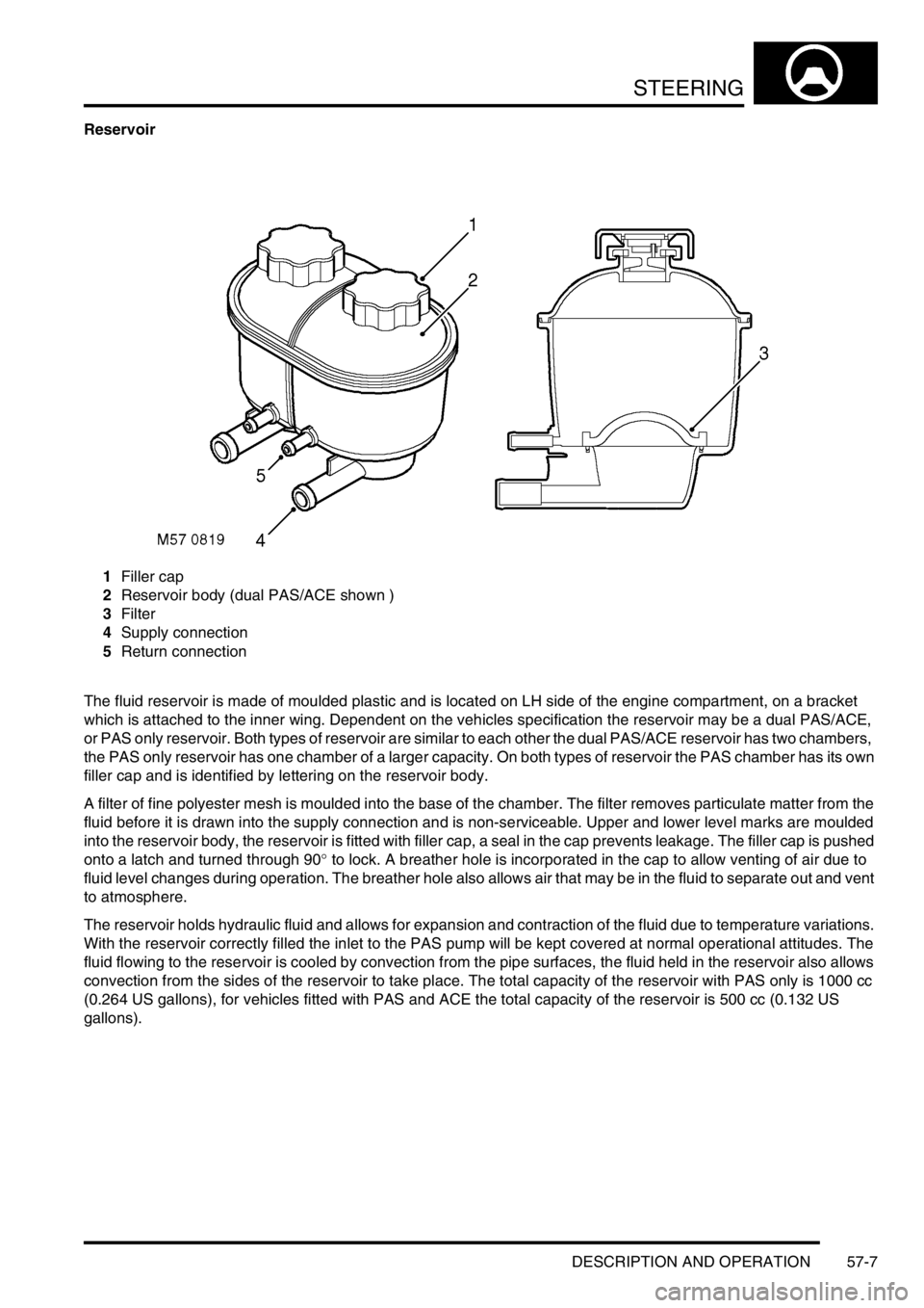
Reservoir
1Filler cap
2Reservoir body (dual PAS/ACE shown )
3Filter
4Supply connection
5Return connection
The fluid reservoir is made of moulded plastic and is located on LH side of the engine compartment, on a bracket
which is attached to the inner wing. Dependent on the vehicles specification the reservoir may be a dual PAS/ACE,
or PAS only reservoir. Both types of reservoir are similar to each other the dual PAS/ACE reservoir has two chambers,
the PAS only reservoir has one chamber of a larger capacity. On both types of reservoir the PAS chamber has its own
filler cap and is identified by lettering on the reservoir body.
A filter of fine polyester mesh is moulded into the base of the chamber. The filter removes particulate matter from the
fluid before it is drawn into the supply connection and is non-serviceable. Upper and lower level marks are moulded
into the reservoir body, the reservoir is fitted with filler cap, a seal in the cap prevents leakage. The filler cap is pushed
onto a latch and turned through 90
° to lock. A breather hole is incorporated in the cap to allow venting of air due to
fluid level changes during operation. The breather hole also allows air that may be in the fluid to separate out and vent
to atmosphere.
The reservoir holds hydraulic fluid and allows for expansion and contraction of the fluid due to temperature variations.
With the reservoir correctly filled the inlet to the PAS pump will be kept covered at normal operational attitudes. The
fluid flowing to the reservoir is cooled by convection from the pipe surfaces, the fluid held in the reservoir also allows
convection from the sides of the reservoir to take place. The total capacity of the reservoir with PAS only is 1000 cc
(0.264 US gallons), for vehicles fitted with PAS and ACE the total capacity of the reservoir is 500 cc (0.132 US
gallons).
Page 915 of 1672

STEERING
57-28 REPAIRS
7. RH drive models:Remove 4 bolts securing oil
filter housing, remove housing and discard 'O'
ring.
CAUTION: Always fit plugs to open
connections to prevent contamination.
8.Remove bolt securing PAS pipe bracket to
steering box, release pipes and discard 'O'
rings.
CAUTION: Always fit plugs to open
connections to prevent contamination.9.Remove securing nut and bolt and release
Panhard rod.
10.Remove nut securing drag link to drop arm.
Using LRT-57-036, break taper joint and
release drag link.
11. RH drive models with ACE: Remove nut
securing anti-roll bar link lower ball joint and
release joint.
Page 916 of 1672

STEERING
REPAIRS 57-29
12. RH drive models with ACE: Position ACE
control arms to access steering box bolts.
13.With assistance remove 4 securing bolts and
remove steering box.
14.Remove centralising bolt from steering box. Refit
1.Fit centralising bolt to steering box.
2. With assistance, position steering box, fit bolts
and tighten to 90 Nm (66 lbf.ft).
3. RH drive models with ACE: Ensure washer is
in place on lower ball joint of anti-roll bar link,
then connect lower ball joint to axle. Tighten nut
to 100 Nm (74 lbf.ft).
4.Position drag link, fit nut and tighten to 80 Nm
(59 lbf.ft).
5.Position Panhard rod, fit bolt and nut and
tighten to 230 Nm (170 lbf.ft).
6.Clean PAS pipe ends and 'O' ring recess.
7.Lubricate new 'O' rings for PAS pipes with clean
PAS fluid.
8.Fit 'O' rings to PAS pipes and position pipes in
steering box. Fit PAS pipe bracket and tighten
bolt to 22 Nm (16 lbf.ft).
9. RHD models: Fit oil filter and housing:
lClean oil filter housing and engine mating
faces.
lLubricate new 'O' ring with clean engine oil
and fit to housing.
lPosition oil filter housing and tighten bolts to
9 Nm (7 lbf.ft).
10.Ensure steering wheel is centralised. Fit
universal joint between steering box and
intermediate shaft and tighten bolts to 25 Nm
(18 lbf.ft).
11.Remove centralising bolt from steering box.
12.Fit road wheel(s) and tighten nuts to 140 Nm
(103 lbf.ft)..
13.Remove stand(s) and lower vehicle.
14.Check and top up engine oil.
15.Bleed PAS system.
+ STEERING, ADJUSTMENTS,
Hydraulic system - bleed.
16.Centralise steering linkage
+ STEERING, ADJUSTMENTS,
Steering linkage - centralise.