LAND ROVER DISCOVERY 2002 Workshop Manual
Manufacturer: LAND ROVER, Model Year: 2002, Model line: DISCOVERY, Model: LAND ROVER DISCOVERY 2002Pages: 1672, PDF Size: 46.1 MB
Page 851 of 1672
AUTOMATIC GEARBOX - ZF4HP22 - 24
44-54 REPAIRS
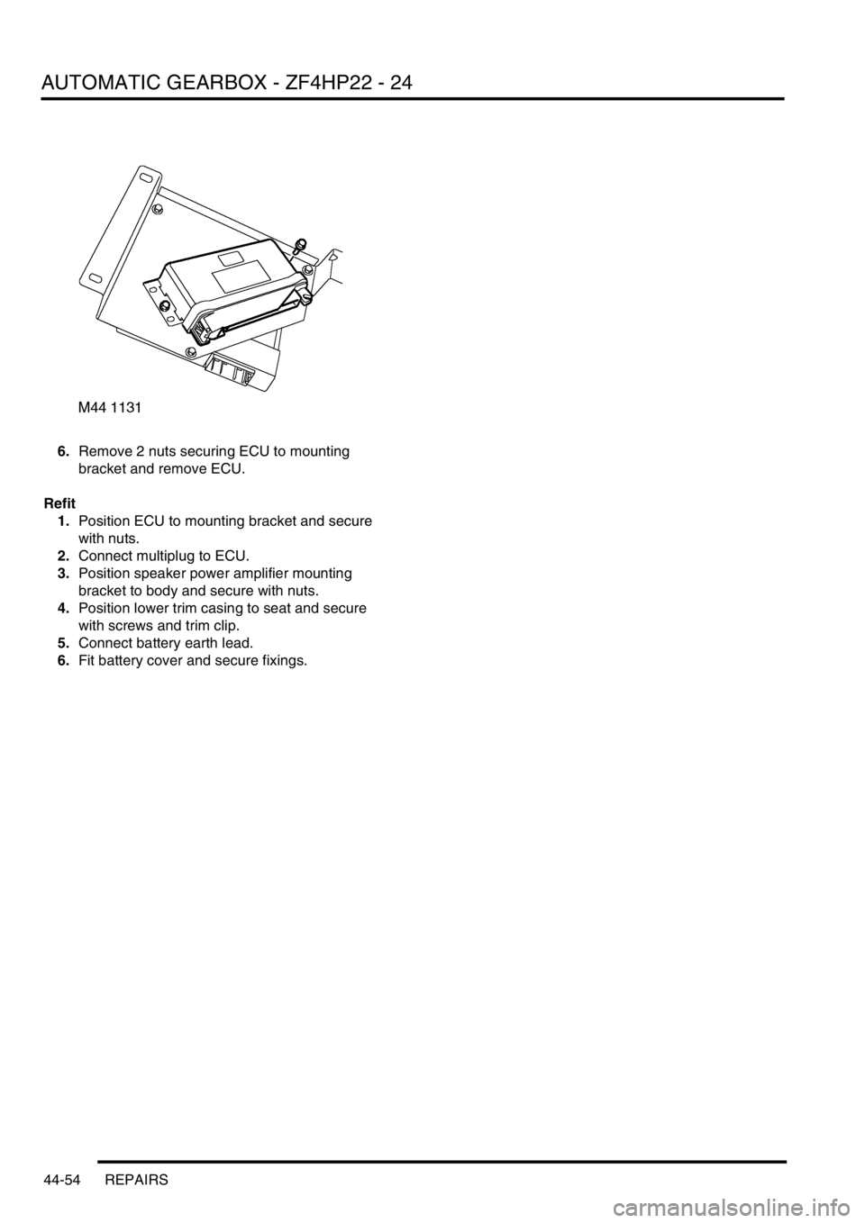
6.Remove 2 nuts securing ECU to mounting
bracket and remove ECU.
Refit
1.Position ECU to mounting bracket and secure
with nuts.
2.Connect multiplug to ECU.
3.Position speaker power amplifier mounting
bracket to body and secure with nuts.
4.Position lower trim casing to seat and secure
with screws and trim clip.
5.Connect battery earth lead.
6.Fit battery cover and secure fixings.
Page 852 of 1672
PROPELLER SHAFTS
DESCRIPTION AND OPERATION 47-1
PROPELLER SH AFTS DESCRIPTION AND OPERAT ION
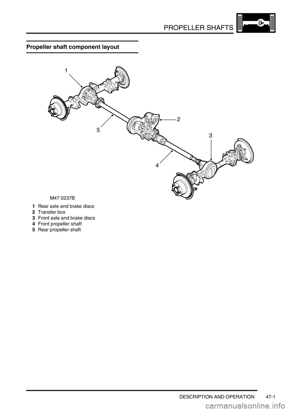
Propeller shaft component layout
1Rear axle and brake discs
2Transfer box
3Front axle and brake discs
4Front propeller shaft
5Rear propeller shaft
M47 0237B
1
2
3
4
5
Page 853 of 1672
PROPELLER SHAFTS
47-2 DESCRIPTION AND OPERATION
Description
General
Front and rear propeller shafts transmit the drive from the transfer box to the axles.
On vehicles from 03 model year fitted with the 4.6l V8 engine and 4HP24 transmission, the front propeller shaft is 15
mm (0.6 in) longer and the rear propeller shaft is 15mm (0.6 in) shorter than those used on vehicles with the 4.0l V8
and Td5 engines. This is to accomodate an increase in length of the 4HP24 transmission.
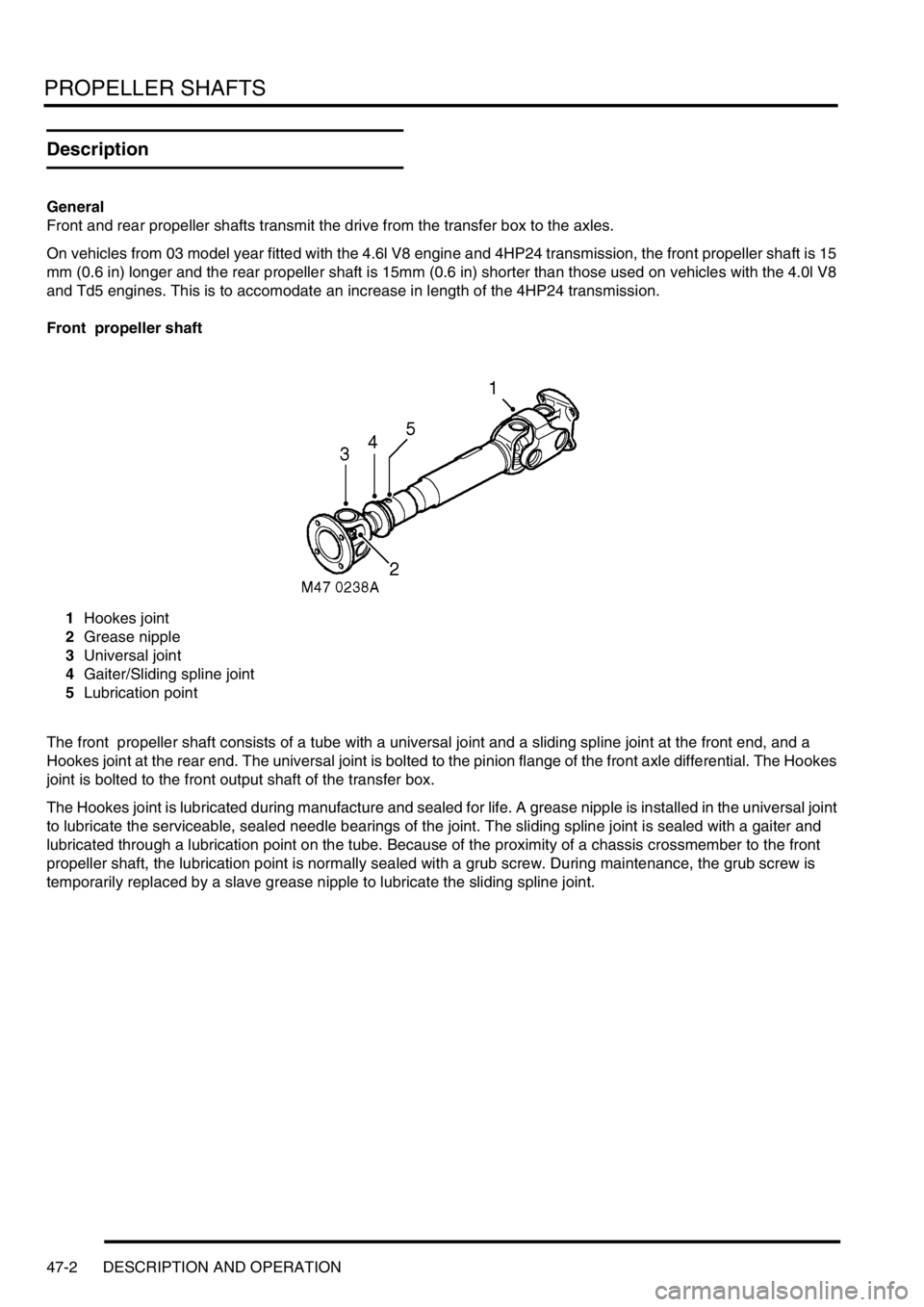
Front propeller shaft
1Hookes joint
2Grease nipple
3Universal joint
4Gaiter/Sliding spline joint
5Lubrication point
The front propeller shaft consists of a tube with a universal joint and a sliding spline joint at the front end, and a
Hookes joint at the rear end. The universal joint is bolted to the pinion flange of the front axle differential. The Hookes
joint is bolted to the front output shaft of the transfer box.
The Hookes joint is lubricated during manufacture and sealed for life. A grease nipple is installed in the universal joint
to lubricate the serviceable, sealed needle bearings of the joint. The sliding spline joint is sealed with a gaiter and
lubricated through a lubrication point on the tube. Because of the proximity of a chassis crossmember to the front
propeller shaft, the lubrication point is normally sealed with a grub screw. During maintenance, the grub screw is
temporarily replaced by a slave grease nipple to lubricate the sliding spline joint.
Page 854 of 1672
PROPELLER SHAFTS
DESCRIPTION AND OPERATION 47-3
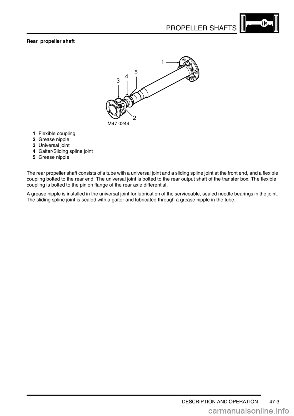
Rear propeller shaft
1Flexible coupling
2Grease nipple
3Universal joint
4Gaiter/Sliding spline joint
5Grease nipple
The rear propeller shaft consists of a tube with a universal joint and a sliding spline joint at the front end, and a flexible
coupling bolted to the rear end. The universal joint is bolted to the rear output shaft of the transfer box. The flexible
coupling is bolted to the pinion flange of the rear axle differential.
A grease nipple is installed in the universal joint for lubrication of the serviceable, sealed needle bearings in the joint.
The sliding spline joint is sealed with a gaiter and lubricated through a grease nipple in the tube.
Page 855 of 1672
PROPELLER SHAFTS
47-4 DESCRIPTION AND OPERATION
Page 856 of 1672
PROPELLER SHAFTS
REPAIRS 47-5
REPAIRS
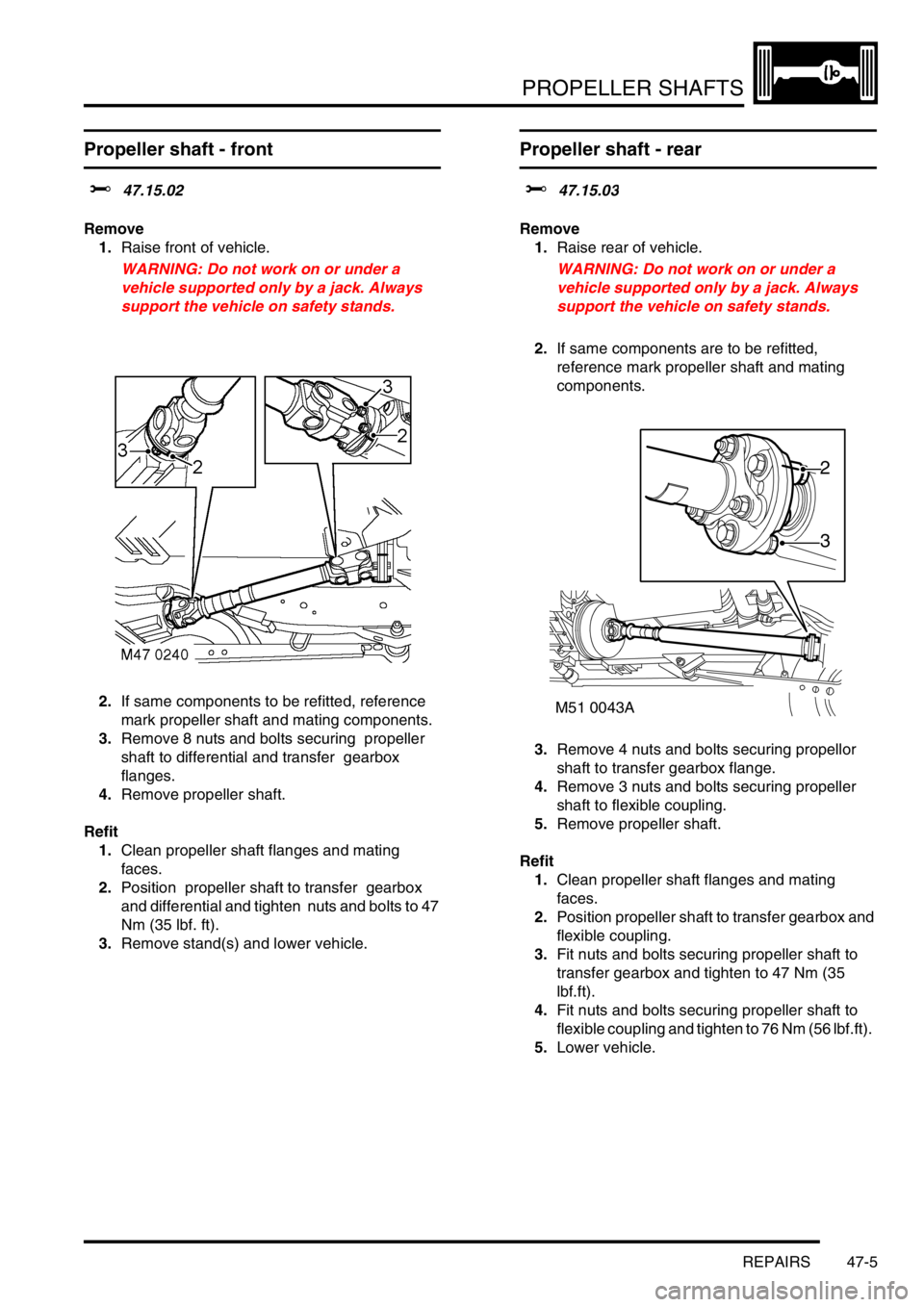
Propeller shaft - front
$% 47.15.02
Remove
1.Raise front of vehicle.
WARNING: Do not work on or under a
vehicle supported only by a jack. Always
support the vehicle on safety stands.
2.If same components to be refitted, reference
mark propeller shaft and mating components.
3.Remove 8 nuts and bolts securing propeller
shaft to differential and transfer gearbox
flanges.
4.Remove propeller shaft.
Refit
1.Clean propeller shaft flanges and mating
faces.
2.Position propeller shaft to transfer gearbox
and differential and tighten nuts and bolts to 47
Nm (35 lbf. ft).
3.Remove stand(s) and lower vehicle.
Propeller shaft - rear
$% 47.15.03
Remove
1.Raise rear of vehicle.
WARNING: Do not work on or under a
vehicle supported only by a jack. Always
support the vehicle on safety stands.
2.If same components are to be refitted,
reference mark propeller shaft and mating
components.
3.Remove 4 nuts and bolts securing propellor
shaft to transfer gearbox flange.
4.Remove 3 nuts and bolts securing propeller
shaft to flexible coupling.
5.Remove propeller shaft.
Refit
1.Clean propeller shaft flanges and mating
faces.
2.Position propeller shaft to transfer gearbox and
flexible coupling.
3.Fit nuts and bolts securing propeller shaft to
transfer gearbox and tighten to 47 Nm (35
lbf.ft).
4.Fit nuts and bolts securing propeller shaft to
flexible coupling and tighten to 76 Nm (56 lbf.ft).
5.Lower vehicle.
M51 0043A
2
3
Page 857 of 1672

PROPELLER SHAFTS
47-6 REPAIRS
Flexible coupling
$% 47.20.08
Remove
1.Raise rear of vehicle.
WARNING: Do not work on or under a
vehicle supported only by a jack. Always
support the vehicle on safety stands.
2.If same components to be refitted, reference
mark flexible coupling and mating components.
3.Remove 3 nuts and bolts securing propeller
shaft to flexible coupling.
4.Move propeller shaft forwards to release from
flexible coupling and differential drive flange
spigot.
5.Tie propeller shaft aside.
6.Remove 3 nuts and bolts securing flexible
coupling to differential drive flange and remove
flexible coupling.Refit
1.Ensure flexible coupling, spigot and drive
flanges are clean.
2.Align the arrows on the flexible coupling with
the securing bolt positions as illustrated. Fit
flexible coupling to differential drive flange and
tighten nuts and bolts to 76 Nm (56 lbf.ft).
3.Fit propeller shaft to spigot and flexible
coupling. Tighten nuts and bolts to 76 Nm (56
lbf.ft).
4.Remove stand(s) and lower vehicle.
Page 858 of 1672
PROPELLER SHAFTS
OVERHAUL 47-7
OVERHAUL
Propeller shaft
$% 47.15.11
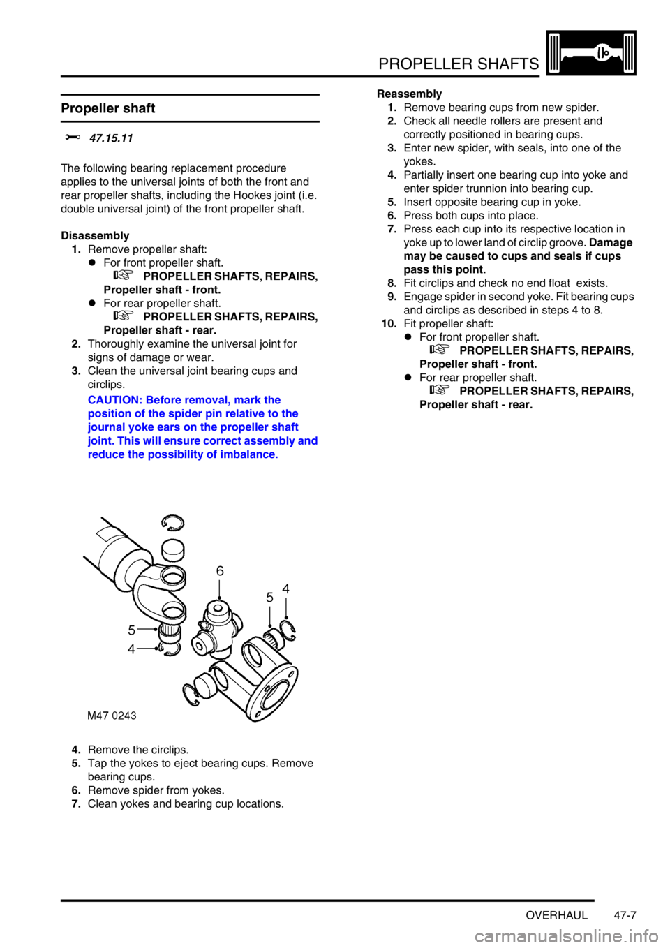
The following bearing replacement procedure
applies to the universal joints of both the front and
rear propeller shafts, including the Hookes joint (i.e.
double universal joint) of the front propeller shaft.
Disassembly
1.Remove propeller shaft:
lFor front propeller shaft.
+ PROPELLER SHAFTS, REPAIRS,
Propeller shaft - front.
lFor rear propeller shaft.
+ PROPELLER SHAFTS, REPAIRS,
Propeller shaft - rear.
2.Thoroughly examine the universal joint for
signs of damage or wear.
3.Clean the universal joint bearing cups and
circlips.
CAUTION: Before removal, mark the
position of the spider pin relative to the
journal yoke ears on the propeller shaft
joint. This will ensure correct assembly and
reduce the possibility of imbalance.
4.Remove the circlips.
5.Tap the yokes to eject bearing cups. Remove
bearing cups.
6.Remove spider from yokes.
7.Clean yokes and bearing cup locations. Reassembly
1.Remove bearing cups from new spider.
2.Check all needle rollers are present and
correctly positioned in bearing cups.
3.Enter new spider, with seals, into one of the
yokes.
4.Partially insert one bearing cup into yoke and
enter spider trunnion into bearing cup.
5.Insert opposite bearing cup in yoke.
6.Press both cups into place.
7.Press each cup into its respective location in
yoke up to lower land of circlip groove. Damage
may be caused to cups and seals if cups
pass this point.
8.Fit circlips and check no end float exists.
9.Engage spider in second yoke. Fit bearing cups
and circlips as described in steps 4 to 8.
10.Fit propeller shaft:
lFor front propeller shaft.
+ PROPELLER SHAFTS, REPAIRS,
Propeller shaft - front.
lFor rear propeller shaft.
+ PROPELLER SHAFTS, REPAIRS,
Propeller shaft - rear.
Page 859 of 1672
PROPELLER SHAFTS
47-8 OVERHAUL
Page 860 of 1672
REAR AXLE
DESCRIPTION AND OPERATION 51-1
REAR AXLE DESCRIPTION AND OPERAT ION
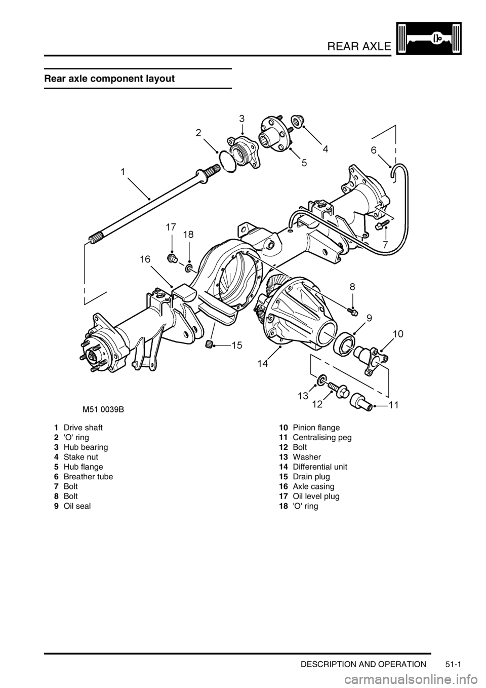
Rear axle component layout
1Drive shaft
2'O' ring
3Hub bearing
4Stake nut
5Hub flange
6Breather tube
7Bolt
8Bolt
9Oil seal10Pinion flange
11Centralising peg
12Bolt
13Washer
14Differential unit
15Drain plug
16Axle casing
17Oil level plug
18'O' ring