LAND ROVER FREELANDER 2001 Workshop Manual
Manufacturer: LAND ROVER, Model Year: 2001, Model line: FREELANDER, Model: LAND ROVER FREELANDER 2001Pages: 1007, PDF Size: 23.47 MB
Page 171 of 1007
MAINTENANCE
10-24 MAINTENANCE
Engine Oil and Filter – KV6
Drain
1.Raise vehicle on ramp.
2.Remove underbelly panel.
+ EXTERIOR FITTINGS, REPAIRS,
Panel - underbelly.
3.Place a suitable container under engine sump
drain plug, remove plug and discard sealing
washer. Allow oil to drain.
WARNING: Observe due care when draining
engine oil as the oil can be very hot.
WARNING: Avoid excessive skin contact
with used engine oil. Used engine oil
contains potentially harmful contaminants
which may cause skin cancer or other
serious skin disorders.
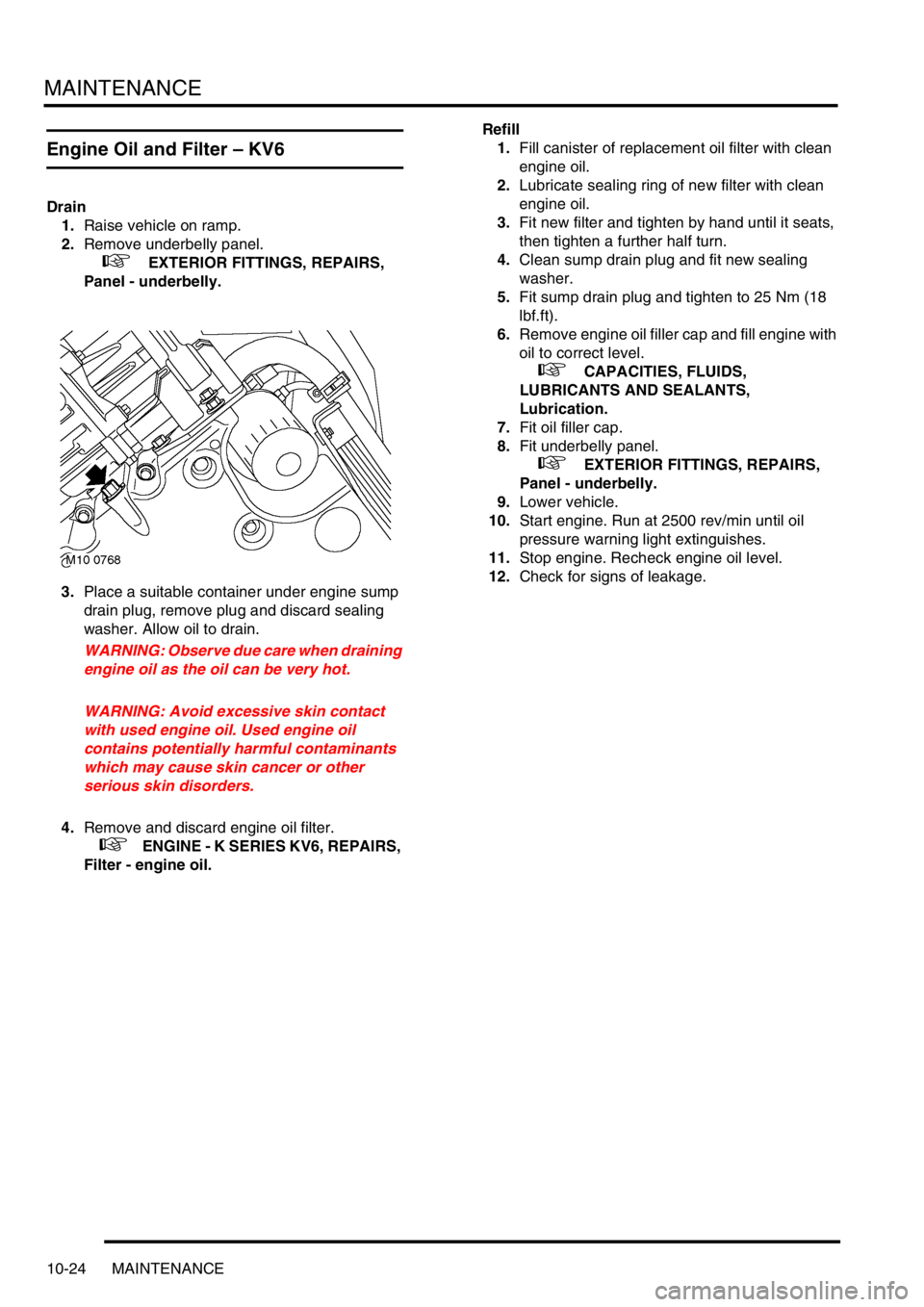
4.Remove and discard engine oil filter.
+ ENGINE - K SERIES KV6, REPAIRS,
Filter - engine oil.Refill
1.Fill canister of replacement oil filter with clean
engine oil.
2.Lubricate sealing ring of new filter with clean
engine oil.
3.Fit new filter and tighten by hand until it seats,
then tighten a further half turn.
4.Clean sump drain plug and fit new sealing
washer.
5.Fit sump drain plug and tighten to 25 Nm (18
lbf.ft).
6.Remove engine oil filler cap and fill engine with
oil to correct level.
+ CAPACITIES, FLUIDS,
LUBRICANTS AND SEALANTS,
Lubrication.
7.Fit oil filler cap.
8.Fit underbelly panel.
+ EXTERIOR FITTINGS, REPAIRS,
Panel - underbelly.
9.Lower vehicle.
10.Start engine. Run at 2500 rev/min until oil
pressure warning light extinguishes.
11.Stop engine. Recheck engine oil level.
12.Check for signs of leakage.
Page 172 of 1007
MAINTENANCE
MAINTENANCE 10-25
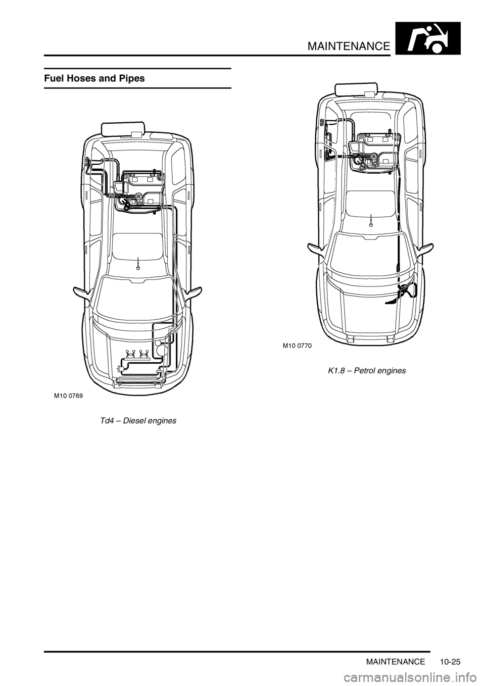
Fuel Hoses and Pipes
Td4 – Diesel enginesK1.8 – Petrol engines
Page 173 of 1007
MAINTENANCE
10-26 MAINTENANCE
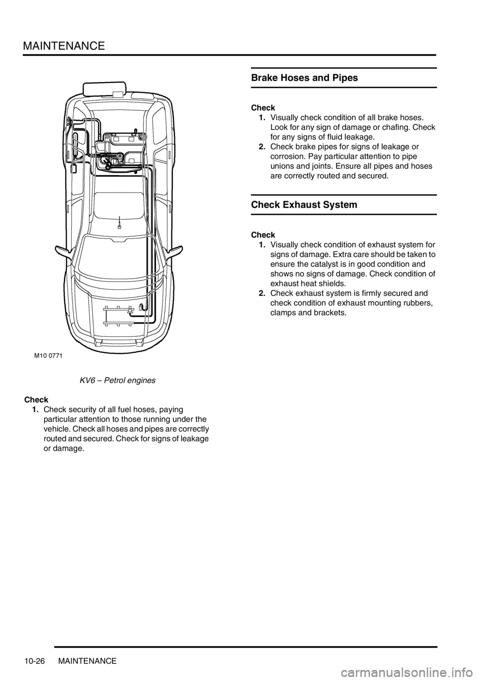
KV6 – Petrol engines
Check
1.Check security of all fuel hoses, paying
particular attention to those running under the
vehicle. Check all hoses and pipes are correctly
routed and secured. Check for signs of leakage
or damage.
Brake Hoses and Pipes
Check
1.Visually check condition of all brake hoses.
Look for any sign of damage or chafing. Check
for any signs of fluid leakage.
2.Check brake pipes for signs of leakage or
corrosion. Pay particular attention to pipe
unions and joints. Ensure all pipes and hoses
are correctly routed and secured.
Check Exhaust System
Check
1.Visually check condition of exhaust system for
signs of damage. Extra care should be taken to
ensure the catalyst is in good condition and
shows no signs of damage. Check condition of
exhaust heat shields.
2.Check exhaust system is firmly secured and
check condition of exhaust mounting rubbers,
clamps and brackets.
Page 174 of 1007
MAINTENANCE
MAINTENANCE 10-27
Suspension
Check Front Suspension
1.Check condition of all ball joint dust covers,
including anti-roll bar links.
2.Check tightness of all accessible suspension
fixings including tie rods.
3.Check wheel bearings and suspension struts
for signs of excessive play or wear.
4.Check track rod ends for wear by attempting to
move the joint forwards and backwards, side to
side and up and down. No wear should be
apparent, if any is detected then the joint must
be replaced.
5.Check for signs of leakage from suspension
dampers.Check Rear Suspension
1.Check tightness of all accessible suspension
fixings including transverse links.
2.Check wheel bearings and suspension struts
for signs of excessive play or wear.
3.Check for signs of leakage from suspension
dampers.
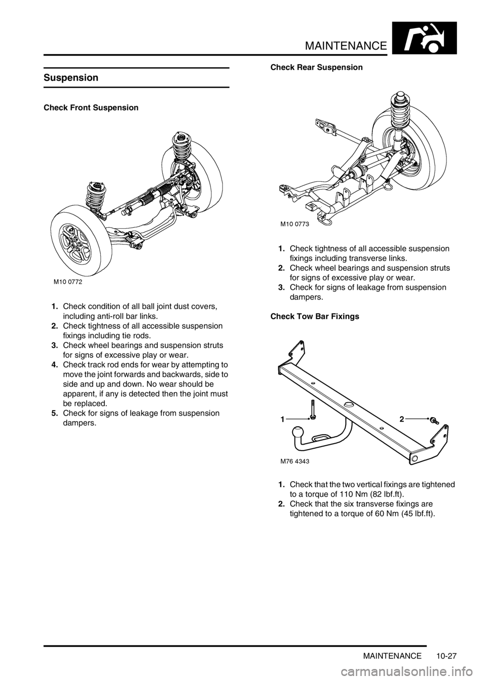
Check Tow Bar Fixings
1.Check that the two vertical fixings are tightened
to a torque of 110 Nm (82 lbf.ft).
2.Check that the six transverse fixings are
tightened to a torque of 60 Nm (45 lbf.ft).
Page 175 of 1007
MAINTENANCE
10-28 MAINTENANCE
Steering
Check
1.Check/tighten steering unit and steering rod
ball joint fixings.
2.Check condition of ball joints and dust covers.
3.Check steering rack bellows for any signs of
leakage.
Road Test
There are two purposes for conducting a road test.
Firstly, to ensure the work completed within the
dealership meets the standards required as laid
down by dealership processes. Secondly, for a
skilled technician to assess the general condition of
the vehicle and report any conditions that the
customer should be made aware of.
CAUTION: Two wheel dynamometer tests must
not be carried out. Four wheel dynamometer
tests must be restricted to 3 mph (5 kph).
Engine Start
1.Check for correct operation of starter switch.
Ensure the engine starts in a correct manner.
Leave the engine running.
Starter Inhibitor Switch – (Automatic only)
1.Select 'D' gear lever position.
2.Check that engine will not start.
3.Select 'R' gear lever position and repeat start
check.
4.Check that engine will start in 'P' and 'N'
positions.
Selector Cable – (Automatic only)
1.Check for correct setting of gear selector cable.
Engine Performance and Throttle Operation
1.Start engine and check that it starts easily.
2.Check that 'oil pressure' and 'no charge'
warning lamps extinguish.
3.Check that throttle pedal movement is free and
unrestricted.
4.Check that engine is responsive to throttle
movement.
Clutch and Gear Selection –
(Manual only, normal driving conditions)
1.Check that clutch engages smoothly without
judder, slipping or noise.
2.Check for abnormal transmission noise.
3.Check for smooth quiet gear changes and that
gear selected engages easily.
Page 176 of 1007

MAINTENANCE
MAINTENANCE 10-29
Gear Change and Parking Pawl Engagement –
(Automatic only, normal driving conditions)
1.Select 'R' and check for smooth take up.
2.Select 'D' and check for smooth up-changes of
ratio from rest.
3.Slow down vehicle and check for smooth down-
changes of ratio.
4.Stop vehicle on a slope.
5.Select 'P' and release handbrake.
6.Check that vehicle does not move and that
selector does not slip out of 'P'.
7.Carry out a similar check with vehicle facing in
the opposite direction.
Steering
1.With vehicle stationary, turn steering from lock
to lock. Check for smooth operation and ensure
there is no undue noise from the power steering
pump or drive belt.
Suspension
1.Check for noise, irregularity in ride (e.g.
dampers) and wheel imbalance.
Foot brake
1.Check for pedal effort, travel, braking
efficiency, pulling and binding.
Handbrake
1.Apply handbrake firmly, check travel and
ratchet hold and release.
Instruments
1.Check for correct operation of all instruments
and warning devices where practical.
Body
1.Check for abnormal body noise.
Seat Belts
1.Check for operation of inertia reels.Road Test
1.Drive vehicle on a short road test. Check all
vehicle systems for correct operation. Pay
particular attention to:
lEngine noise
lGearbox noise
lSuspension noise
lBody noise
lBraking system operation
lGear selection
lEngine performance
2.Where possible, check for correct operation of
Hill Descent Control (HDC) system. This should
not be carried out if excessive journey time is
required.
3.After road test, carry out a final inspection of the
vehicle on vehicle ramps.
4.Check all underbonnet fluid levels and top-up if
necessary.
Page 177 of 1007
MAINTENANCE
10-30 MAINTENANCE
Endorse Service Record
Check
1.Insert date and mileage of next service.
2.Insert current mileage.
3.Tick one of the boxes on the brake fluid
replacement indicator.
4.Tick one of the boxes on the camshaft drive belt
indicator.
5.Endorse service record with dealer stamp.
6.Sign and date the service record.
7.Sign and date the maintenance check sheet.
Report any Unusual Features
Check
1.Produce a written report detailing additional
work necessary, or items which may require
attention prior to the next service.
Page 178 of 1007
ENGINE - K SERIES KV6
ADJUSTMENTS 12-3-1
ENGIN E - K SERIES KV6 ADJUST ME NTS
Engine oil pressure check
$% 12.90.09.01
Check
1.Remove oil pressure switch.
+ ENGINE - K SERIES KV6, REPAIRS,
Switch - oil pressure.
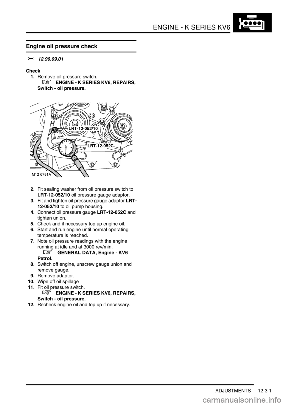
2.Fit sealing washer from oil pressure switch to
LRT-12-052/10 oil pressure gauge adaptor.
3.Fit and tighten oil pressure gauge adaptor LRT-
12-052/10 to oil pump housing.
4.Connect oil pressure gauge LRT-12-052C and
tighten union.
5.Check and if necessary top up engine oil.
6.Start and run engine until normal operating
temperature is reached.
7.Note oil pressure readings with the engine
running at idle and at 3000 rev/min.
+ GENERAL DATA, Engine - KV6
Petrol.
8.Switch off engine, unscrew gauge union and
remove gauge.
9.Remove adaptor.
10.Wipe off oil spillage
11.Fit oil pressure switch.
+ ENGINE - K SERIES KV6, REPAIRS,
Switch - oil pressure.
12.Recheck engine oil and top up if necessary.
Page 179 of 1007

Page 180 of 1007
ENGINE - K SERIES KV6
REPAIRS 12-3-3
REPAIRS
Camshafts - LH cylinder head
$% 12.13.02
Remove
1.Disconnect battery earth lead.
2.Remove camshaft timing belt.
+ ENGINE - K SERIES KV6, REPAIRS,
Camshaft timing belt.
3.Remove LH camshaft rear timing belt.
+ ENGINE - K SERIES KV6, REPAIRS,
Camshaft rear timing belt - LH cylinder
head.
4.Remove LH camshaft cover gasket.
+ ENGINE - K SERIES KV6, REPAIRS,
Camshaft cover gasket - LH - Up to 03MY.
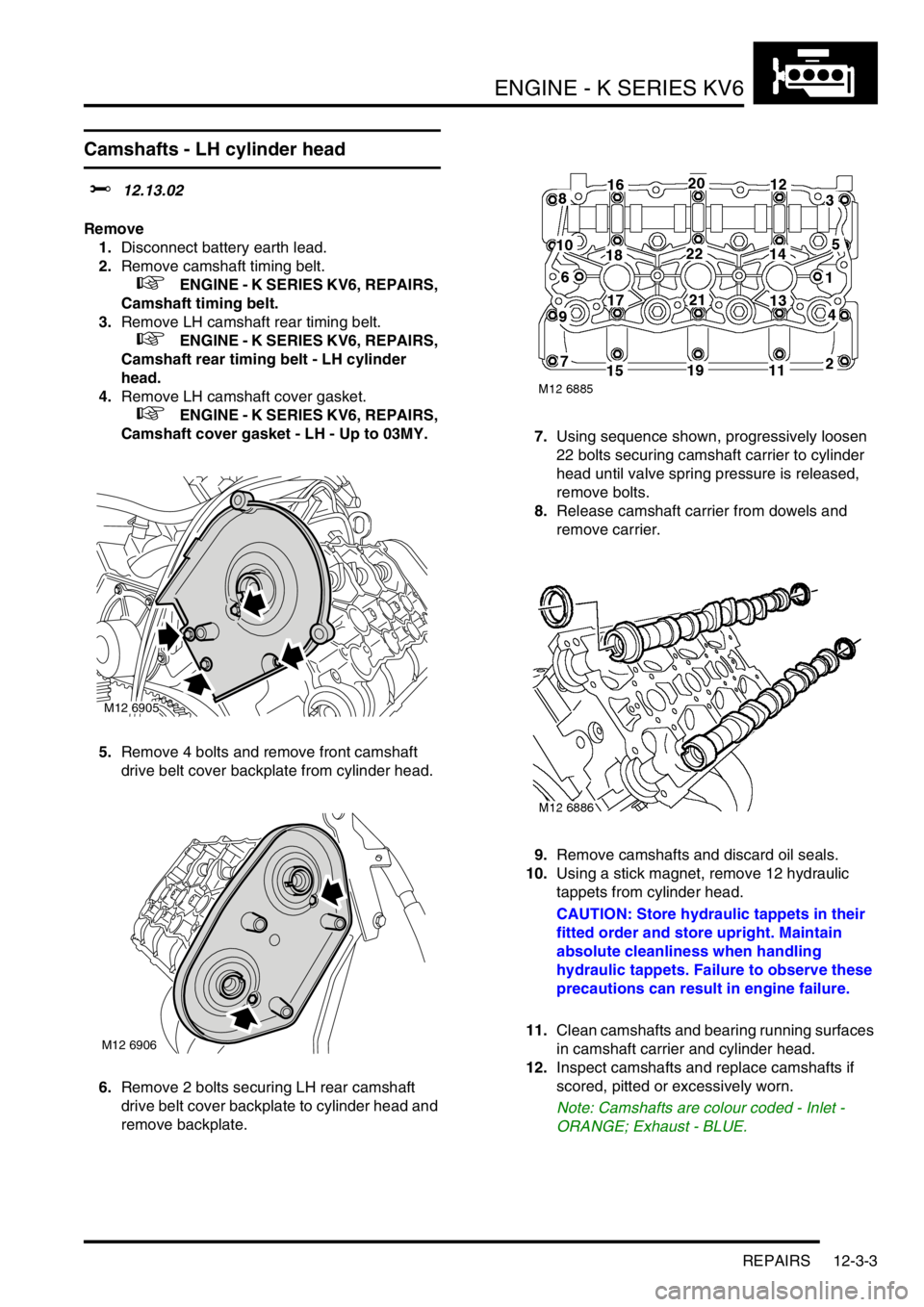
5.Remove 4 bolts and remove front camshaft
drive belt cover backplate from cylinder head.
6.Remove 2 bolts securing LH rear camshaft
drive belt cover backplate to cylinder head and
remove backplate.7.Using sequence shown, progressively loosen
22 bolts securing camshaft carrier to cylinder
head until valve spring pressure is released,
remove bolts.
8.Release camshaft carrier from dowels and
remove carrier.
9.Remove camshafts and discard oil seals.
10.Using a stick magnet, remove 12 hydraulic
tappets from cylinder head.
CAUTION: Store hydraulic tappets in their
fitted order and store upright. Maintain
absolute cleanliness when handling
hydraulic tappets. Failure to observe these
precautions can result in engine failure.
11.Clean camshafts and bearing running surfaces
in camshaft carrier and cylinder head.
12.Inspect camshafts and replace camshafts if
scored, pitted or excessively worn.
Note: Camshafts are colour coded - Inlet -
ORANGE; Exhaust - BLUE.
M12 6905
M12 6906