LAND ROVER FRELANDER 2 2006 Repair Manual
Manufacturer: LAND ROVER, Model Year: 2006, Model line: FRELANDER 2, Model: LAND ROVER FRELANDER 2 2006Pages: 3229, PDF Size: 78.5 MB
Page 1801 of 3229
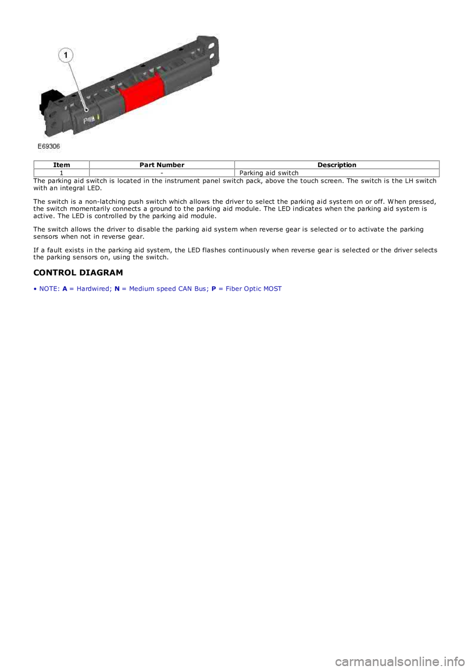
ItemPart NumberDescription
1-Parking aid s wit chThe parking ai d s wit ch is locat ed in the ins trument panel swit ch pack, above t he t ouch s creen. The swi tch i s t he LH s wit chwit h an integral LED.
The s wit ch is a non-lat chi ng pus h swi tch whi ch allows the driver to sel ect t he parking ai d s ys t em on or off. W hen pres sed,t he swit ch momentari ly connect s a ground to t he parki ng aid module. The LED i ndi cat es when t he parking ai d s ys t em i sact ive. The LED i s cont roll ed by t he parking ai d module.
The s wit ch allows the driver to di s abl e t he parking ai d s ys t em when revers e gear i s s elected or t o acti vat e t he parkings ens ors when not in reverse gear.
If a fault exi st s i n the parking aid sys t em, the LED flas hes cont inuousl y when revers e gear is sel ect ed or the driver s el ect st he parking s ensors on, us i ng the swi tch.
CONTROL DIAGRAM
• NOTE: A = Hardwi red; N = Medium s peed CAN Bus ; P = Fiber Opt ic MOST
Page 1802 of 3229
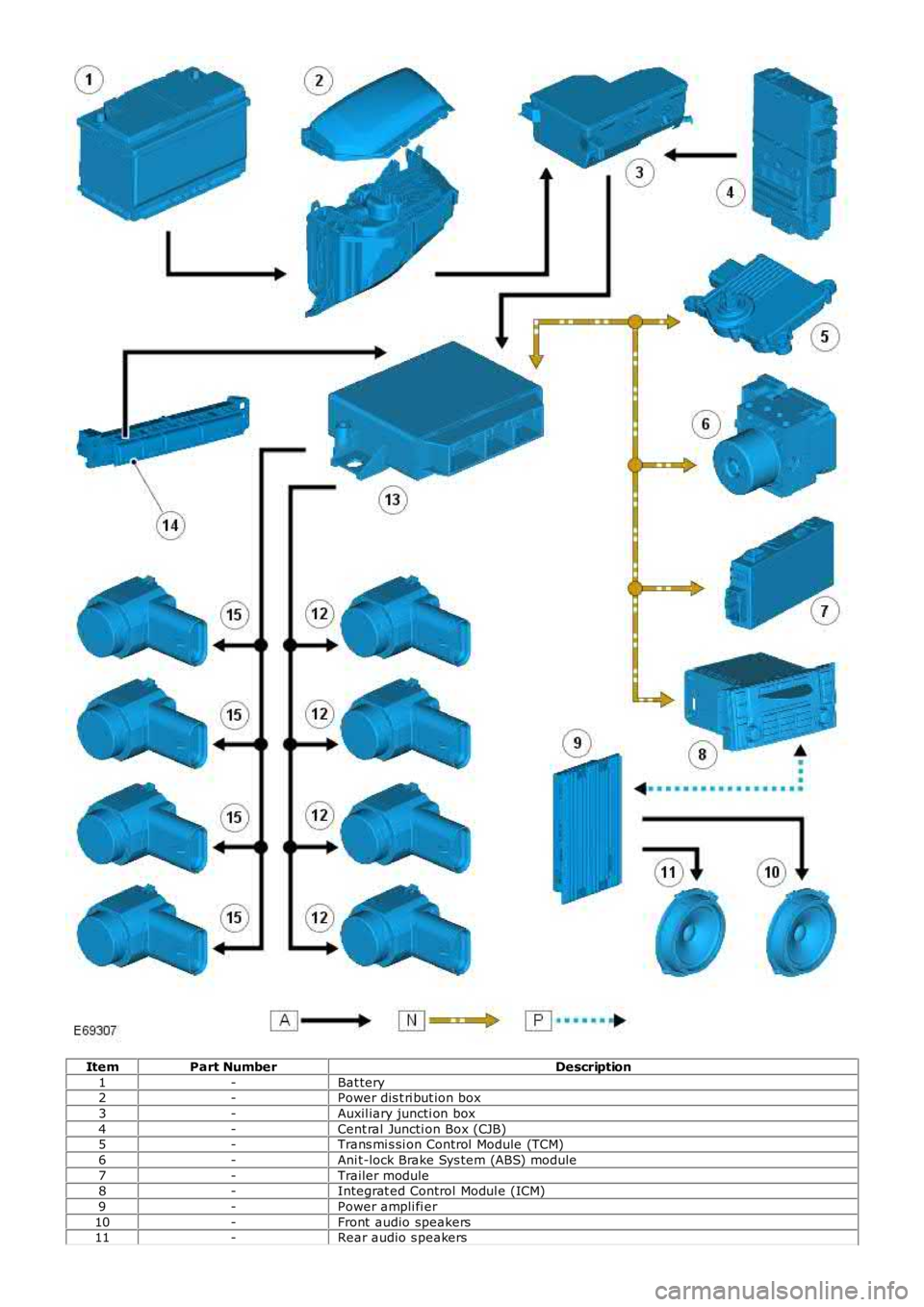
ItemPart NumberDescription
1-Bat tery2-Power dis t ri but ion box
3-Auxil iary juncti on box
4-Cent ral Juncti on Box (CJB)5-Trans mi s si on Control Module (TCM)
6-Ani t-lock Brake Sys tem (ABS) module
7-Trailer module8-Integrat ed Control Modul e (ICM)
9-Power ampli fi er
10-Front audio speakers11-Rear audio s peakers
Page 1803 of 3229
12-Rear parking ai d s ensor
13-Parki ng aid modul e
14-Parki ng aid swi tch15-Front parki ng aid sens or
PRINCIPLES OF OPERATION
W hen t he parking ai d module act ivates t he s yst em, t he s wit ch LED is i ll uminated and a s ingle tone i s emit ted from t hefront and rear audi o s peakers to indicate that the sys tem is operati ng. The parki ng aid module then proces s es si gnal sreceived from the s ens ors t o determine if t here is an object wit h t he det ecti on range of the sens ors .
In the combi ned mode, t he s ensors emit a s eries of ult ras onic i mpuls es and t hen swi tch t o recei ver mode t o recei ve theecho refl ect ed by an obs tacle wit hin t he detecti on range. The received echo si gnal s are amplified and converted from ananal ogue si gnal t o a di git al s i gnal by t he s ens or. The di gi tal s ignal is pas s ed to the parki ng aid modul e and compared wi thpre-programmed dat a s t ored i n an EEPRO M wi thin the modul e. The modul e receives t his data via t he s ignal line from t hes ens or and cal cul ates t he dis t ance from the object us ing the el aps ed t ime bet ween t he transmit ted and recei ved i mpuls e.The durat ion of t he impuls e durati on is det ermi ned by the modul e, wit h the sens or cont roll ing t he frequency of t he impuls eoutput.
In receiver mode, t he s ensor receives i mpuls es that were emit t ed by adjacent s ensors. The modul e us es thi s informat iont o precis ely det ermi ne the pos it ion and di s tance of the object .
If no object s are detected t here are no furt her warning t ones . If an object is detect ed, repeat ed audi ble t ones are emi tt edfrom ei ther t he front or rear audio s peakers as appropriate. The t ime delay between t he t ones decreas es as the di s tancebetween t he object and the vehicle decreas es , unt il at approximat ely 250 mm (10 inches), t he audi bl e t one becomescont inuous.
If, aft er the init ial detecti on of an object, t here i s no decrease in di st ance bet ween t he object and t he vehicle, t he audi bl ewarni ng tones remain const ant if t he object is det ect ed by a central s ens or or s t ops after 3 seconds if t he object i sdetected by a corner sens or.
The audi ble t ones wil l st op i f the vehicle is moved out of revers e gear. The module cont inues to monit or the di st ance andwil l res ume t he warni ng tones i f a decreas e in di st ance is detect ed.
Syst em operat ion i s cancell ed when t he parking ai d s wit ch is press ed or t he ignit ion i s s wit ched off. Sys tem operati on isals o cancel led i f the vehicle travels more than 50 m (164 ft ) or the vehicle forward s peed exceeds 30 km/h (19 mph).
The s ys t em can detect when a t rai ler is connect ed t o t he vehi cl e by a mess age output on t he medium s peed CAN bus fromt he trailer module. W hen the parki ng aid modul e detects that a t rai ler is connect ed t o the vehicl e, t he rear s ensors aredis abled t o prevent cons tant warni ngs due to the cl os e proxi mit y of t he trail er.
The parking ai d module al s o incorporat es s oftware t hat compens at es for t he effect s of fros t, i ce or rain on the sens ors . Icecompens ati on occurs if t he ambient t emperature, recei ved on a medium s peed CAN bus mes sage from t he ins trumentclus ter, is l es s t han 6°C (43°F).
Distance Calculation
• NOTE: A = Int ermit tent warni ng tone; B = Conti nuous warni ng t one
Page 1804 of 3229
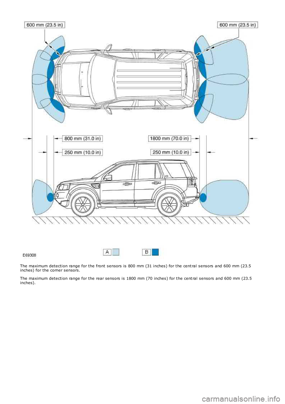
The maximum detecti on range for the front s ensors is 800 mm (31 i nches ) for t he central s ens ors and 600 mm (23.5inches) for the corner s ensors.
The maximum detecti on range for the rear sens ors i s 1800 mm (70 inches ) for t he central s ensors and 600 mm (23.5inches).
Page 1805 of 3229

Publi s hed: 11-May-2011
Parking Aid - Parking Aid
Diagnosi s and Tes ti ng
Principle of Operation
For a detail ed descripti on of the parki ng aid sys tem, refer t o t he rel evant Des cription and Operat ion s ecti on in theworks hop manual .REFER to: Parki ng Aid (413-13 Parki ng Aid, Descripti on and Operat ion).
Inspection and Verification
CAUTION: Di agnos is by s ubs ti tut ion from a donor vehicle is NO T acceptabl e. Subs ti tut ion of cont rol modules doesnot guarant ee confirmat ion of a faul t, and may als o caus e addit ional fault s i n t he vehi cl e being t est ed and/or t he donorvehi cl e.
1. Verify t he cus t omer concern.1.
2. Vis ually ins pect for obvious s igns of damage and s ys t em i ntegri ty.2.
• NOTE: Part icular att enti on s hould be paid t o t he fol lowi ng it ems where DTCs may not be logged:
Check for cont aminati on (e.g. dirt, gri me, fros ti ng, i ce) around t he parking ai d s ensors, i f s o refer to the parki ng aids ect ion i n t he vehi cl e handbook.Check for the correct ins tall ati on and ali gnment of t he s ens ors to t he bumper.Spurious det ect ion of t he ground may occur duri ng front s ys t em operat ion on an up-s lope, or down s l ope.
Visual Inspection
ElectricalFuse(s )Relay(s )W iri ng Harnes sElectrical connect or(s )Front parking ai d s ensor(s ) and holdersRear parking aid s ens or(s ) and hol dersAudio s ys tem.REFER to: Informati on and Entert ainment Syst em (415-01 Informati on and Entertainment Sys tem, Di agnos is andTes ti ng).Parking ai d s wit ch and LEDParking ai d module
3. If an obvious cause for an obs erved or report ed concern is found, correct t he caus e (if pos s ible) beforeproceeding t o t he next s t ep.3.
4. If t he caus e is not vis ually evi dent , check for Di agnos ti c Trouble Codes (DTCs) and refer t o t he DTC Index.4.
DTC Index
• NOTE: If the control modul e is sus pect and t he vehicle remains under manufact urer warranty, refer to the W arrant y Poli cyand Procedures manual (s ect ion B1.2), or determine i f any prior approval programme is i n operat ion, prior t o t heins t al lat ion of a new modul e.
• NOTE: Generic scan t ool s may not read the codes li st ed, or may read only fi ve digit codes . Mat ch the five di git s from t hes can tool to the firs t fi ve di git s of the seven digi t code l is ted to ident ify t he faul t (t he las t t wo digi ts gi ve addi ti onalinformat ion read by the manufact urer approved diagnos t ic s ys tem).
• NOTE: W hen performing volt age or res is t ance t est s , always use a digi tal mult imeter (DMM) accurat e t o t hree deci malplaces, and wi th an up-t o-date cal ibrat ion cert ificate. W hen tes ti ng res is t ance al ways take t he res is t ance of t he DMMleads i nt o account .
• NOTE: Check and recti fy bas ic faul ts before beginni ng diagnos t ic rout ines i nvol vi ng pinpoint t es t s.
• NOTE: Ins pect connect ors for s igns of water ingres s , and pins for damage and/or corros ion.
• NOTE: If DTCs are recorded and, aft er performi ng the pi npoi nt tes ts , a fault is not present , an int ermi tt ent concern maybe t he caus e. Always check for loose connect ions and corroded terminals .
• NOTE: W hen carrying out repair/di agnos is of t he s yst em, on removal of t he front or rear bumper ins pect t he s ensorconnectors to ens ure they were correct ly l atched and check fly l eads for si gns of chaffing or t rapped wi res .
For a compl ete lis t of all Di agnos ti c Trouble Codes (DTCs) t hat could be logged on this vehicle, pleas e refer to Sect ion100-00
REFER to: Di agnos ti c Trouble Code (DTC) Index - DTC: Parking Ai d Module (PAM) (100-00 General Informat ion, Des cri pti onand Operat ion).
Page 1806 of 3229
Publi s hed: 11-May-2011
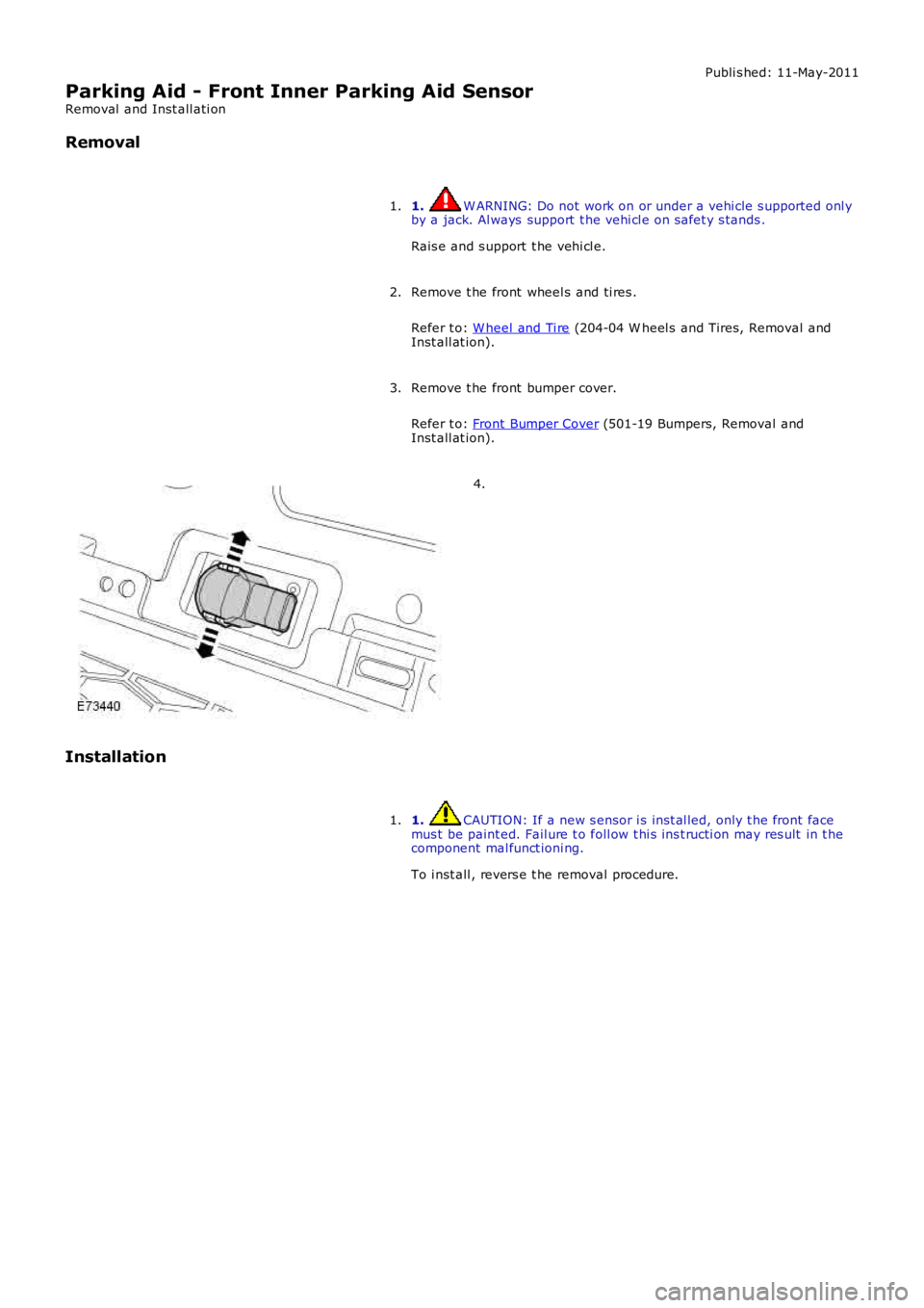
Parking Aid - Front Inner Parking Aid Sensor
Removal and Inst all ati on
Removal
1. W ARNING: Do not work on or under a vehi cle s upported onl yby a jack. Al ways support t he vehi cl e on s afet y s tands .
Rais e and s upport t he vehi cl e.
1.
Remove t he front wheel s and ti res .
Refer t o: W heel and Ti re (204-04 W heel s and Tires, Removal andInst all at ion).
2.
Remove t he front bumper cover.
Refer t o: Front Bumper Cover (501-19 Bumpers, Removal andInst all at ion).
3.
4.
Installation
1. CAUTION: If a new s ensor i s ins t al led, only t he front facemus t be paint ed. Fail ure t o foll ow t hi s ins t ructi on may res ult in t hecomponent mal funct ioni ng.
To i nst all , revers e t he removal procedure.
1.
Page 1807 of 3229
Publi s hed: 11-May-2011
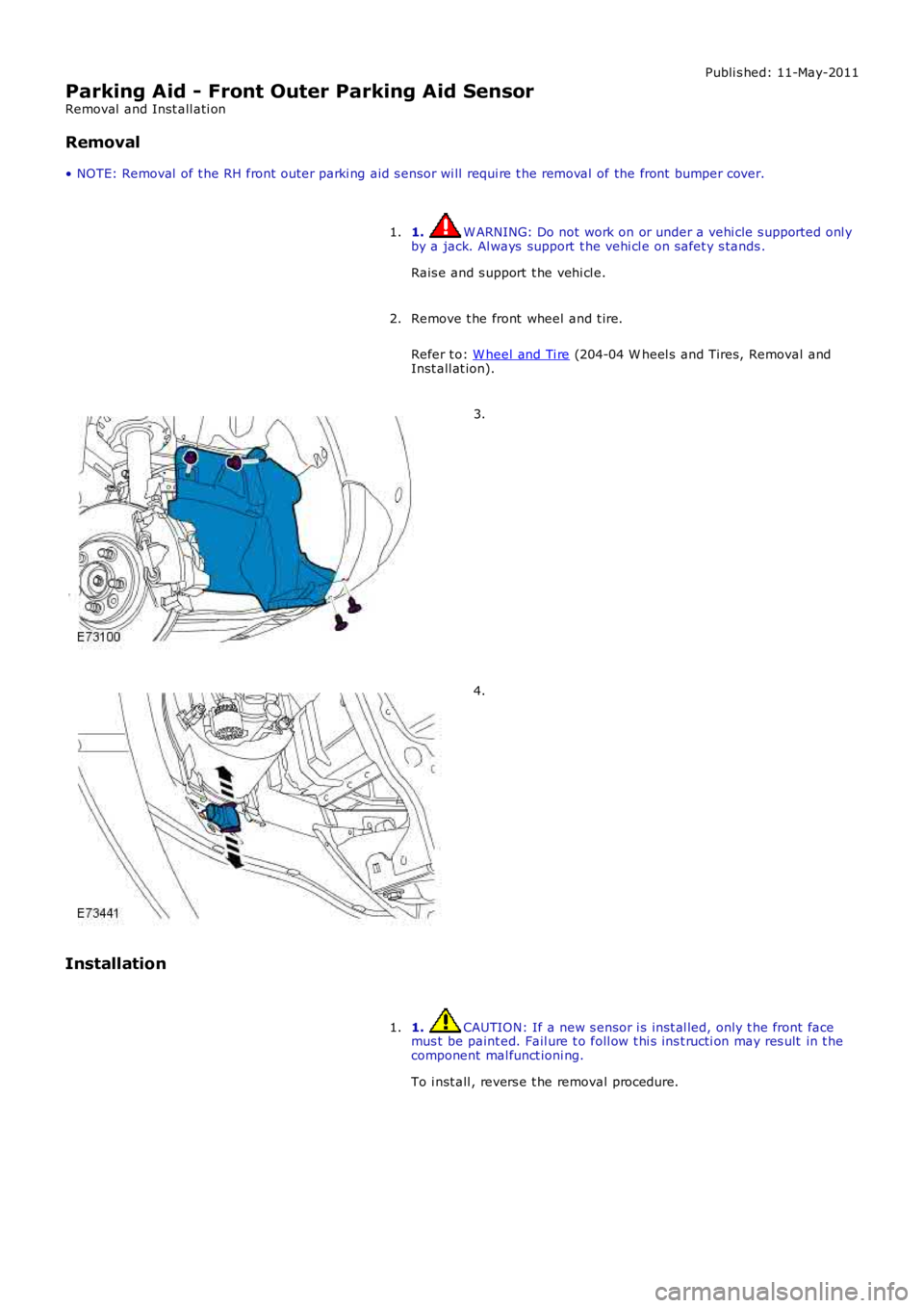
Parking Aid - Front Outer Parking Aid Sensor
Removal and Inst all ati on
Removal
• NOTE: Removal of t he RH front outer parki ng aid s ensor wi ll requi re t he removal of the front bumper cover.
1. W ARNING: Do not work on or under a vehi cle s upported onl yby a jack. Al ways support t he vehi cl e on s afet y s tands .
Rais e and s upport t he vehi cl e.
1.
Remove t he front wheel and t ire.
Refer t o: W heel and Ti re (204-04 W heel s and Tires, Removal andInst all at ion).
2.
3.
4.
Installation
1. CAUTION: If a new s ensor i s ins t al led, only t he front facemus t be paint ed. Fail ure t o foll ow t hi s ins t ructi on may res ult in t hecomponent mal funct ioni ng.
To i nst all , revers e t he removal procedure.
1.
Page 1808 of 3229
Publi s hed: 11-May-2011
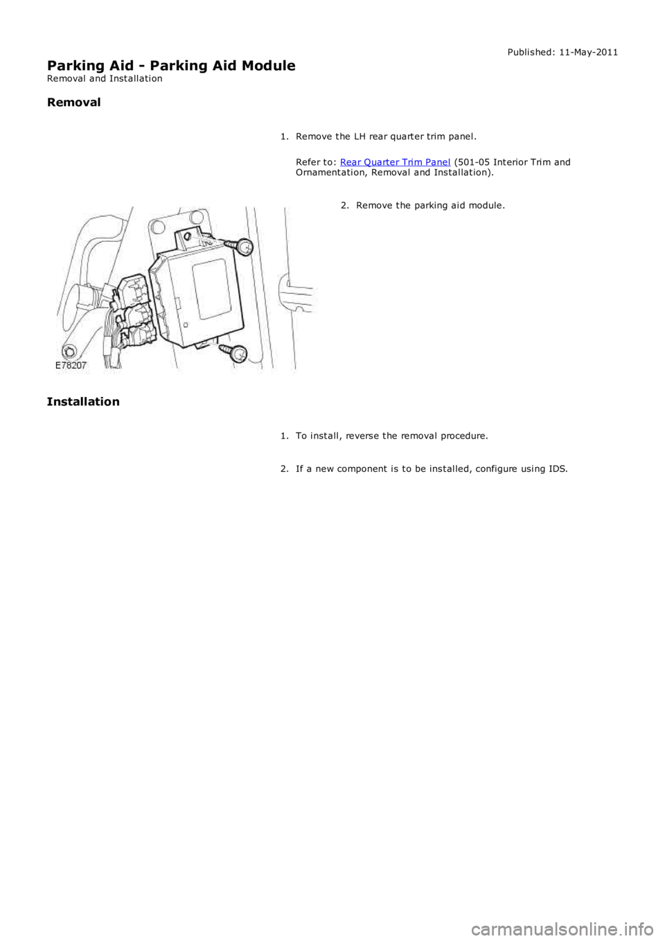
Parking Aid - Parking Aid Module
Removal and Inst all ati on
Removal
Remove t he LH rear quart er trim panel .
Refer t o: Rear Quarter Tri m Panel (501-05 Int erior Tri m andOrnament ati on, Removal and Ins tal lat ion).
1.
Remove t he parking ai d module.2.
Installation
To i nst all , revers e t he removal procedure.1.
If a new component i s t o be ins t al led, configure usi ng IDS.2.
Page 1809 of 3229
Publi s hed: 11-May-2011
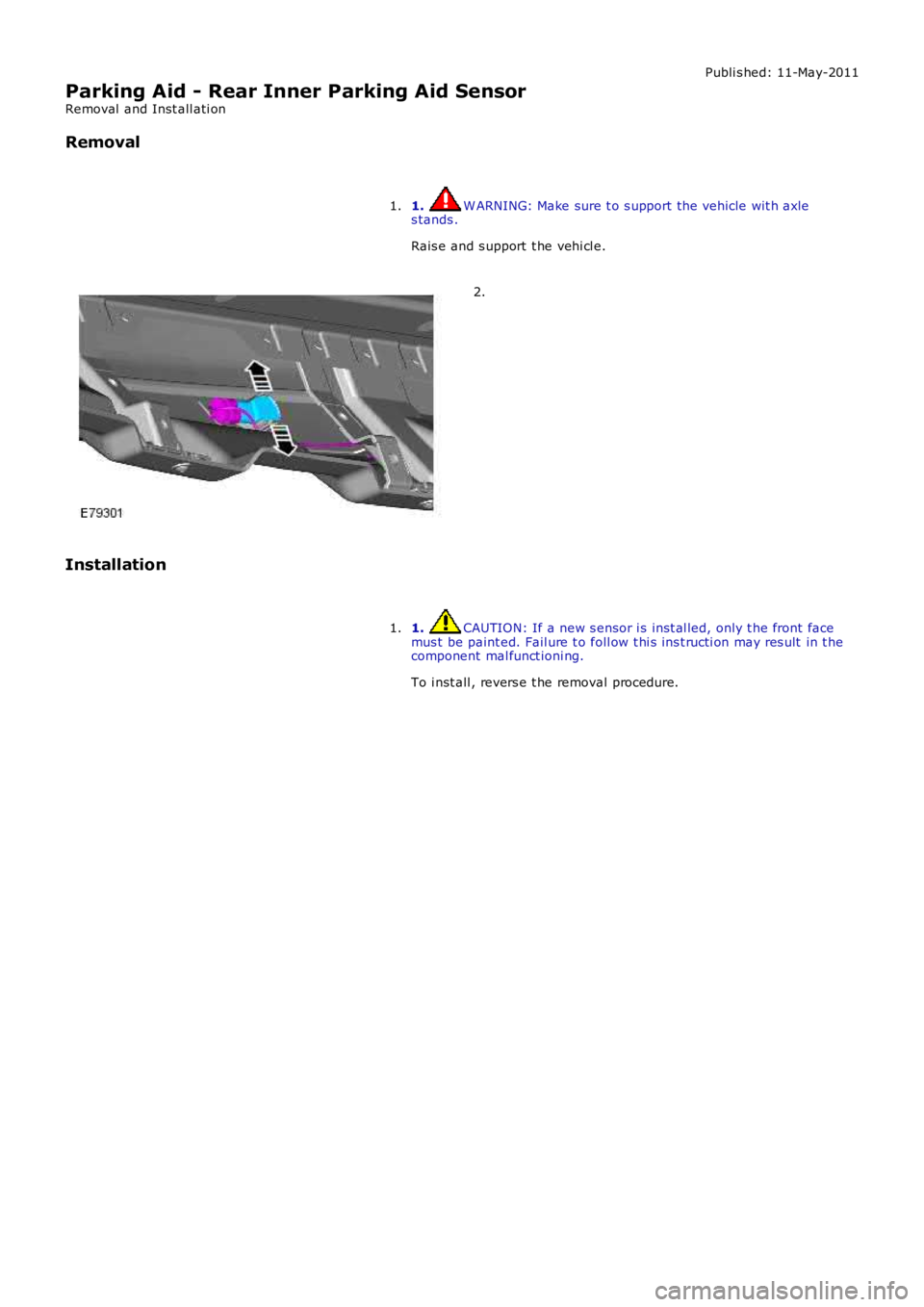
Parking Aid - Rear Inner Parking Aid Sensor
Removal and Inst all ati on
Removal
1. W ARNING: Make sure t o s upport the vehicle wit h axles tands .
Rais e and s upport t he vehi cl e.
1.
2.
Installation
1. CAUTION: If a new s ensor i s ins t al led, only t he front facemus t be paint ed. Fail ure t o foll ow t hi s ins t ructi on may res ult in t hecomponent mal funct ioni ng.
To i nst all , revers e t he removal procedure.
1.
Page 1810 of 3229
Publi s hed: 11-May-2011
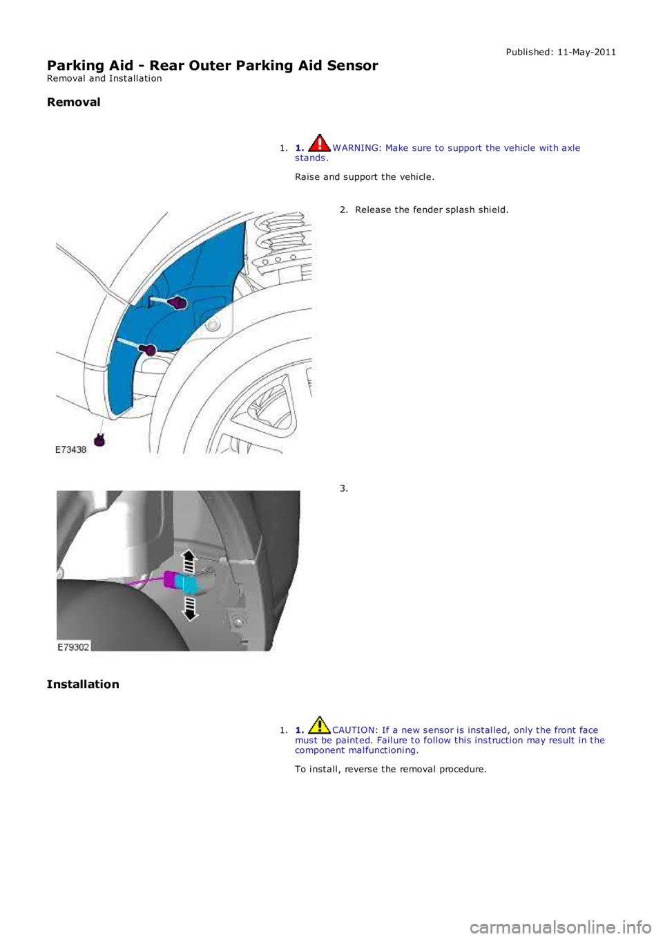
Parking Aid - Rear Outer Parking Aid Sensor
Removal and Inst all ati on
Removal
1. W ARNING: Make sure t o s upport the vehicle wit h axles tands .
Rais e and s upport t he vehi cl e.
1.
Releas e t he fender spl as h shi el d.2.
3.
Installation
1. CAUTION: If a new s ensor i s ins t al led, only t he front facemus t be paint ed. Fail ure t o foll ow t hi s ins t ructi on may res ult in t hecomponent mal funct ioni ng.
To i nst all , revers e t he removal procedure.
1.