LAND ROVER FRELANDER 2 2006 Repair Manual
Manufacturer: LAND ROVER, Model Year: 2006, Model line: FRELANDER 2, Model: LAND ROVER FRELANDER 2 2006Pages: 3229, PDF Size: 78.5 MB
Page 1821 of 3229
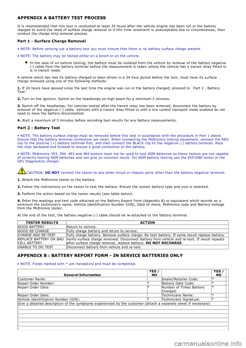
APPENDIX A BATTERY TEST PROCESS
It is recommended t hat this tes t is conduct ed at leas t 24 hours after t he vehi cl e engine has been run or t he batt erycharged to avoi d the need of s urface charge removal or i f thi s t ime cons traint is unaccept abl e due t o circums t ances , thenconduct the charge s t ri p removal process .
Part 1 - Surface Charge Removal
• NOTE: Before carryi ng out a batt ery t est you must ens ure t hat there is no bat t ery s urface charge present .
• NOTE: The batt ery may be t es t ed eit her on a bench or on t he vehicle.
In the cas e of on-vehicle tes ti ng, t he batt ery must be is olated from t he vehi cl e by removal of t he bat t ery negati ve(-) cable from the bat tery t ermi nal before t he measurement is t aken unl ess the vehicle has a transi t rel ay fi tt ed oris in t rans it mode.
A vehicle which has had it s batt ery charged or been dri ven in a 24 hour period before t he tes t , must have i ts s urfacecharge removed us ing one of t he fol lowi ng methods :
1. If 24 hours have pas s ed s ince the las t ti me t he engine was run or the bat tery charged, proceed t o `Part 2 - Bat teryTest '.
2. Turn on t he i gni ti on. Swi tch on t he headlamps on hi gh beam for a mini mum 3 minut es .
3. Swit ch off t he headl amps . For vehi cl es tes t ed aft er t he t rans it relay has been removed, di s connect t he batt ery byremoval of the negati ve (-) cabl e. Vehi cl es wit h a trans i t relay fit t ed or wit h a l ow current t rans port mode enabled do notneed to have t he batt ery di s connect ed.
4. W ait a maximum of 5 mi nut es before recordi ng tes t res ult s for any bat tery measurements .
Part 2 - Battery Test
• NOTE: The batt ery s urface charge mus t be removed before t his t est i n accordance with the procedure in Part 1 above.Ensure t hat t he batt ery terminal connect ors are clean. W hen connecti ng t he Midt ronics t est ing equipment , connect the REDclip to the pos it ive (+) batt ery terminal fi rs t, and t hen connect the BLACK cl ip t o t he negat ive (-) bat tery t ermi nal . Rockt he cl ips backward and forward to ens ure a good connecti on to the bat tery.
• NOTE: Mi dt roni cs 393, 394. 493 and 494 t es ters mus t not be us ed t o t est AGM batt eri es as thes e t est ers are not capableof correctl y t es t ing AGM batt eries and can gi ve an incorrect resul t. For AGM batt ery tes ti ng us e the EXP1080 t es t er or t heGR1 Di agnos ti cs charger.
CAUTION: DO NOT connect t he t es t er to any ot her ci rcuit or chas s is poi nt ot her than t he batt ery negati ve terminal.
1. Att ach the Midtronics tes t er t o t he batt ery.
2. Fol low the i nst ruct ions on t he tes t er t o t est the bat tery. Ens ure t he correct batt ery type and s ize i s s elect ed.
3. Perform the acti on based on the t es ter res ult s (s ee table bel ow).
4. Ent er the readings and t es t code obtained on the Bat tery Report Form (Appendi x B) or equi val ent whi ch records as ami ni mum the t echni ci an's name, Vehi cl e Ident ificati on Number (VIN), Dat e of check, Midtronics code and Bat t ery Volt agefrom the Mi dtroni cs tes ter.
At t he end of the t est , t he bat t ery negati ve (-) cabl e s houl d be re-att ached to t he batt ery terminal.
T EST ER RESULT SACT ION
GOOD BATTERYReturn t o s ervice.
GOOD RE-CHARGEFully charge bat tery and ret urn to servi ce.CHARGE AND RE-TESTFully charge bat tery. Remove s urface charge. Re-tes t batt ery. If s ame res ult repl ace bat tery.
REPLACE BATTERY OR BADCELL BATTERYVeri fy s urface charge removed. Dis connect bat tery from vehicle and re-tes t. If res ult repeat saft er surface charge removal , replace batt ery. DO NOT RECHARGE.
UNABLE TO DO TESTDis connect batt ery from vehi cl e and re-t es t .
APPENDIX B : BATTERY REPORT FORM - IN SERVICE BATTERIES ONLY
• NOTE: Fields marked wi th * are mandat ory and mus t be complet ed.
General InformationYES /NO YES /NO
Cus tomer Name: Dealer/Retai ler Code:*
Repair Order Number:*Batt ery Dat e Code:* Repair Order Dat e:*Number of Ti mes Bat teryCharged:*
Repair Order Dat e: Technici ans Name:*
Vehicle Identi fi cat ion Number (VIN):*Technici ans Si gnat ure:*
Gi ve a detail ed descripti on of the sympt oms experienced by the cus tomer (att ach a s eparate sheet if necess ary)-
-
--
-
-
Page 1822 of 3229
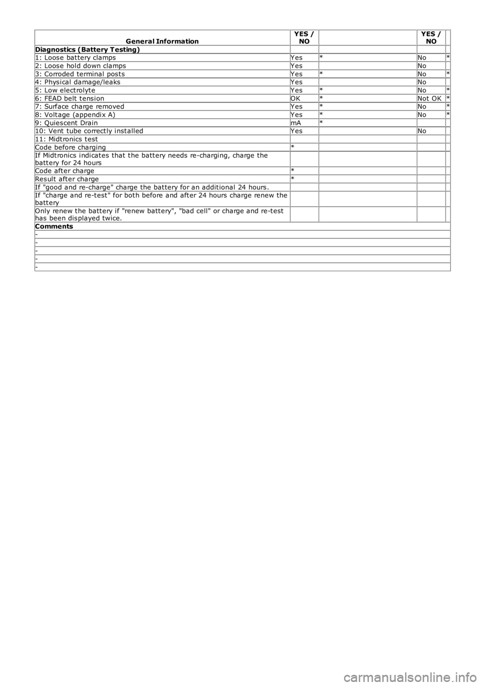
General InformationYES /NO YES /NO
Diagnostics (Battery T esting) 1: Loos e bat tery clampsY es*No*
2: Loos e hol d down clampsY es No
3: Corroded terminal pos t sY es*No*4: Phys i cal damage/leaksY es No
5: Low elect rolyt eY es*No*
6: FEAD belt t ens i onOK*Not OK*7: Surface charge removedY es*No*
8: Volt age (appendi x A)Y es*No*
9: Quies cent DrainmA* 10: Vent tube correct ly i nst all edY es No
11: Midt ronics t est
Code before charging* If Midt ronics i ndi cat es that t he batt ery needs re-chargi ng, charge thebatt ery for 24 hours
Code aft er charge*
Res ul t aft er charge*
If "good and re-charge" charge the bat tery for an addit ional 24 hours . If "charge and re-t est " for bot h before and aft er 24 hours charge renew thebatt ery
Only renew t he batt ery i f "renew batt ery", "bad cell" or charge and re-t esthas been dis played twice.
Comments-
-
--
-
Page 1823 of 3229
Publ is hed: 20-Oct -2011
Battery and Charging System - General Information - Quiescent Drain
Des cript ion and Operat ion
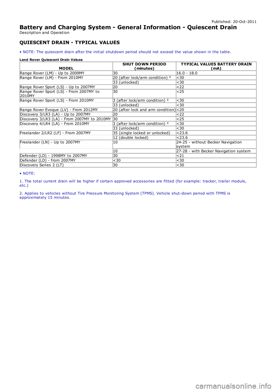
QUIESCENT DRAIN - TYPICAL VALUES
• NOTE: The quies cent drai n aft er the init ial s hut down peri od s hould not exceed the val ue shown in t he t abl e.
Land Rover Quiescent Drain Values
MODELSHUT DO WN PER IOD(minutes)T YPICAL VALUES BAT T ERY DRAIN(mA)
Range Rover (LM) - Up t o 2009MY3016.0 - 18.0Range Rover (LM) - From 2010MY20 (aft er l ock/arm condit ion) ²<30
33 (unl ocked)<30
Range Rover Sport (LS) - Up t o 2007MY20<22Range Rover Sport (LS) - From 2007MY t o2010MY30<25
Range Rover Sport (LS) - From 2010MY3 (aft er lock/arm condit ion) ²<30
33 (unl ocked)<30
Range Rover Evoque (LV) - From 2012MY20 (aft er l ock and arm condit ion)<20Di scovery 3/LR3 (LA) - Up t o 2007MY20<22
Di scovery 3/LR3 (LA) - From 2007MY to 2010MY30<25
Di scovery 4/LR4 (LA) - From 2010MY3 (aft er lock/arm condit ion) ²<3033 (unl ocked)<30
Freelander 2/LR2 (LF) - From 2007MY35 (si ngl e l ocked or unlocked)<23.6
12 (double locked)<23.6Freelander (LN) - Up to 2007MY1024-25 - wi thout Becker Navi gati onsys t em
1027-28 - wi th Becker Navi gat ion s ys temDefender (LD) - 1998MY t o 2007MY30<21
Defender (LD) - from 2007MY<30<30
Di scovery Seri es 2 (LT)30<30
• NOTE:
1. The tot al current drain wil l be higher i f certai n approved acces sories are fi tt ed (for exampl e: tracker, t rai ler module,etc.)
2. Appl ies t o vehicles wi thout Tire Pres s ure Monit ori ng Syst em (TPMS). Vehicle shut -down peri od wi th TPMS isapproximat el y 15 minutes .
Page 1824 of 3229
Publ is hed: 05-Dec-2011
Battery and Charging System - General Information - Charging System
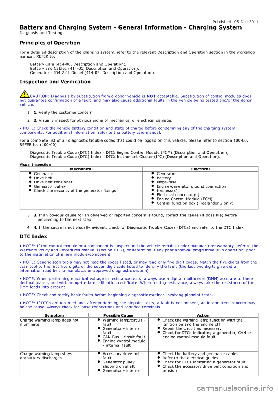
Diagnosi s and Tes ti ng
Principles of Operation
For a detail ed descripti on of the chargi ng s ys t em, refer t o t he rel evant Des cript ion and Operat ion secti on in the workshopmanual. REFER to:
Bat t ery Care (414-00, Des cript ion and Operat ion),Bat t ery and Cables (414-01, Des cri pti on and Operati on),Generator - ID4 2.4L Di esel (414-02, Des cri pt ion and Operati on).
Inspection and Verification
CAUTION: Di agnos is by s ubs ti tut ion from a donor vehicle is NO T acceptabl e. Subs ti tut ion of cont rol modules doesnot guarant ee confirmat ion of a faul t, and may als o caus e addit ional fault s i n t he vehi cl e being t est ed and/or t he donorvehi cl e.
1. Verify t he cus t omer concern.1.
2. Vis ually ins pect for obvious s igns of mechani cal or electrical damage.2.
• NOTE: Check the vehicle bat tery condi ti on and st ate of charge before condemning any of the chargi ng s ys t emcomponents . For addi ti onal i nformat ion, refer to the bat tery care manual.
For a compl ete lis t of all di agnos ti c troubl e codes that coul d be l ogged on t his vehicle, pleas e refer to s ect ion 100-00.REFER to: (100-00)
Diagnos t ic Troubl e Code (DTC) Index - DTC: Engine Cont rol Module (PCM) (Des cri pt ion and Operati on),Diagnos t ic Troubl e Code (DTC) Index - DTC: Ins trument Clus ter (IPC) (Des cri pti on and Operati on).
Visual Inspection
MechanicalElectricalGenerat orDrive beltDrive belt t ensi onerGenerat or pull eyCheck the s ecurit y of t he generat or fi xings
Generat orBat teryMega-fus eEngine/generat or ground connecti onHarness (s)El ect ri cal connector(s )Engine Cont rol Module (ECM)Cent ral juncti on box (Freel ander 2 onl y)
3. If an obvious cause for an obs erved or report ed concern is found, correct t he caus e (if pos s ible) beforeproceeding t o t he next s t ep3.
4. If t he caus e is not vis ually evi dent , check for Di agnos ti c Trouble Codes (DTCs) and refer t o t he DTC Index.4.
DTC Index
• NOTE: If the control modul e or a component i s s us pect and the vehicle remains under manufacturer warrant y, refer t o theW arranty Pol icy and Procedures manual (s ect ion B1.2), or determine i f any pri or approval programme is in operat ion, pri ort o the ins tall ati on of a new module/component.
• NOTE: Generic scan t ool s may not read the codes li st ed, or may read only fi ve digit codes . Mat ch the five di git s from t hes can tool to the firs t fi ve di git s of the seven digi t code l is ted to ident ify t he faul t (t he las t t wo digi ts gi ve ext rainformat ion read by the manufact urer-approved diagnost ic s ys tem).
• NOTE: W hen performing el ect ri cal volt age or resi s tance tes t s, al ways us e a digit al mult imet er (DMM) accurate to threedeci mal places , and wi th an up-to-date cali brat ion cert ificate. W hen t es ti ng res is t ance, always take t he res i st ance of t heDMM leads int o account.
• NOTE: Check and recti fy bas ic faul ts before beginni ng diagnos t ic rout ines i nvol vi ng pinpoint t es t s.
• NOTE: If DTCs are recorded and, aft er performi ng the pi npoi nt tes ts , a fault is not present , an int ermi tt ent concern maybe t he caus e. Always check for loose connect ions and corroded terminals .
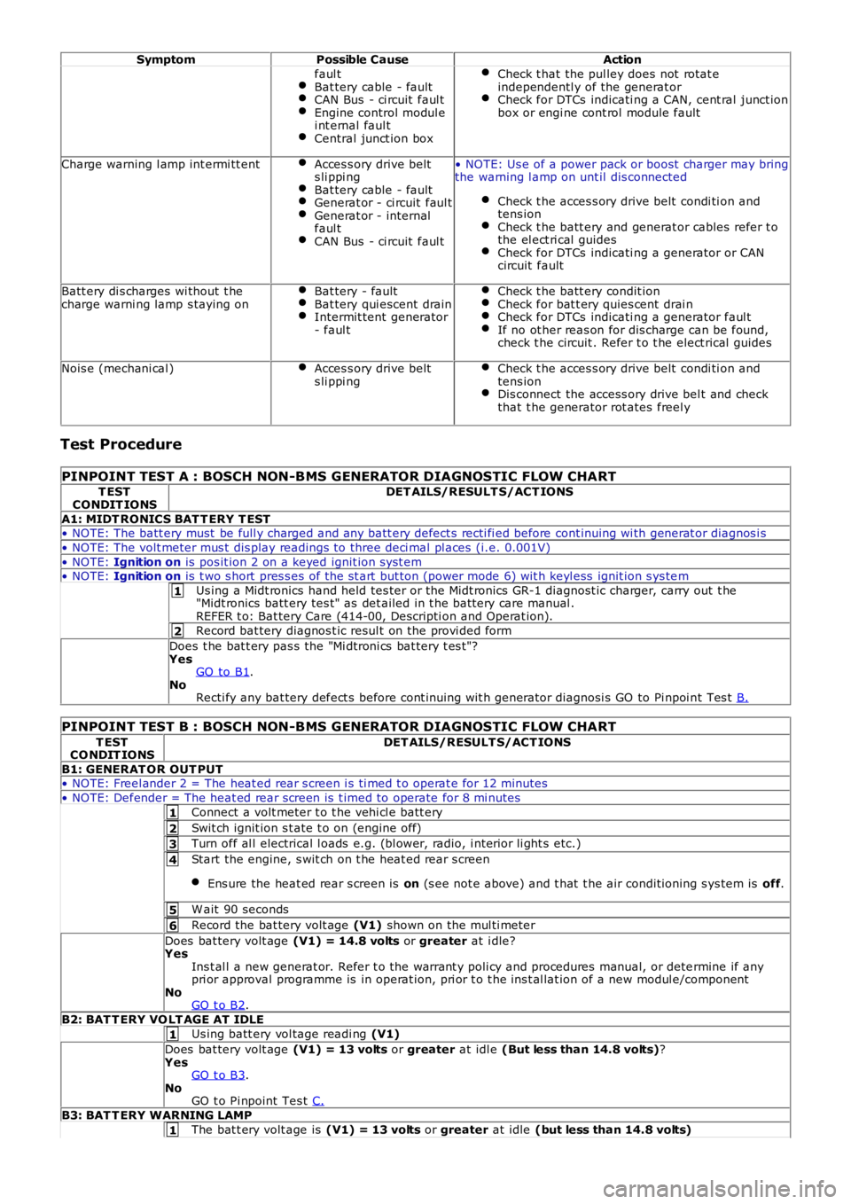
SymptomPossible CauseAction
Charge warning l amp does noti llumi nateW arning l amp/circui t -faul tGenerat or - internalfaul tCAN Bus - ci rcuit faul tEngine control modul e- i nternal faul t
Check t he warni ng lamp functi on wit h t heignit ion on and the engine offRepai r the ci rcuit as neces s aryCheck for DTCs indicati ng a generator, CAN orengi ne cont rol module fault
Charge warning l amp s tayson/bat tery dis chargesAcces s ory drive belt -faul tGenerat or pul leys li ppi ng on s haftGenerat or - internal
Check t he batt ery and generat or cablesRefer t o the el ect ri cal guidesCheck for DTCs indicati ng a generator faul tCheck t he acces s ory drive belt condi ti on andtens ion
Page 1825 of 3229
1
2
1
2
3
4
5
6
1
1
SymptomPossible CauseAction
faul tBat tery cable - faultCAN Bus - ci rcuit faul tEngine control modul ei nt ernal faul tCentral junct ion box
Check t hat the pul ley does not rotat eindependentl y of the generat orCheck for DTCs indicati ng a CAN, cent ral junct ionbox or engi ne cont rol module fault
Charge warning l amp int ermi tt entAcces s ory drive belts li ppi ngBat tery cable - faultGenerat or - ci rcuit faul tGenerat or - internalfaul tCAN Bus - ci rcuit faul t
• NOTE: Us e of a power pack or boost charger may bringthe warning l amp on unt il dis connected
Check t he acces s ory drive belt condi ti on andtens ionCheck t he batt ery and generat or cables refer t othe el ect ri cal guidesCheck for DTCs indicati ng a generator or CANcircuit fault
Batt ery di s charges wi thout t hecharge warni ng lamp s taying onBat tery - faultBat tery qui escent drainIntermit tent generator- faul t
Check t he batt ery condit ionCheck for bat t ery quies cent drai nCheck for DTCs indicati ng a generator faul tIf no ot her reas on for dis charge can be found,check t he circuit . Refer t o t he elect rical guides
Nois e (mechani cal )Acces s ory drive belts li ppi ngCheck t he acces s ory drive belt condi ti on andtens ionDis connect the access ory drive bel t and checkthat t he generator rot ates freel y
Test Procedure
PINPOINT TEST A : BOSCH NON-BMS GENERATOR DIAGNOSTIC FLOW CHART
T ESTCONDIT IONSDET AILS/RESULT S/ACT IONS
A1: MIDT RONICS BAT T ERY T EST• NOTE: The batt ery must be full y charged and any batt ery defect s recti fi ed before cont inuing wi th generat or diagnos i s
• NOTE: The volt meter mus t dis play readings to three deci mal pl aces (i.e. 0.001V)
• NOTE: Ignition on is pos it ion 2 on a keyed ignit ion s yst em• NOTE: Ignition on is t wo s hort pres s es of the st art but ton (power mode 6) wit h keyl ess ignit ion s ys tem
Us ing a Midt ronics hand held tes ter or t he Midt ronics GR-1 diagnost ic charger, carry out t he"Midt ronics batt ery tes t" as det ailed in t he batt ery care manual .REFER t o: Bat tery Care (414-00, Descripti on and Operat ion).
Record bat tery diagnos t ic resul t on the provi ded form
Does t he bat t ery pas s the "Mi dtroni cs bat tery t es t "?YesGO to B1.NoRecti fy any bat tery defect s before cont inuing wit h generator diagnosi s GO to Pi npoi nt Tes t B.
PINPOINT TEST B : BOSCH NON-BMS GENERATOR DIAGNOSTIC FLOW CHART
T ESTCO NDIT IONSDET AILS/RESULT S/ACT IONS
B1: GENERAT OR OUT PUT• NOTE: Freel ander 2 = The heat ed rear s creen i s ti med t o operat e for 12 minutes
• NOTE: Defender = The heat ed rear s creen is t imed to operate for 8 mi nutes
Connect a volt meter t o t he vehi cl e batt ery
Swit ch ignit ion s t ate t o on (engine off)
Turn off al l electrical l oads e.g. (bl ower, radio, i nteri or li ght s etc.)
Start the engine, s wit ch on t he heat ed rear s creen
Ens ure the heat ed rear s creen is on (s ee not e above) and t hat t he air condit ioning s ys tem is off.
W ait 90 seconds
Record the bat tery volt age (V1) shown on the mul ti meter
Does bat tery volt age (V1) = 14.8 volts or greater at i dle?YesIns t al l a new generat or. Refer t o the warrant y poli cy and procedures manual, or determine if anypri or approval programme is in operat ion, pri or t o t he ins t al lat ion of a new modul e/componentNoGO t o B2.
B2: BAT T ERY VO LT AGE AT IDLE
Us ing batt ery vol tage readi ng (V1)
Does bat tery volt age (V1) = 13 volts or greater at idl e (But less than 14.8 volts)?YesGO t o B3.NoGO t o Pi npoint Tes t C.
B3: BAT T ERY WARNING LAMP
The bat t ery volt age is (V1) = 13 volts or greater at idle (but less than 14.8 volts)
Page 1826 of 3229
1
2
1
2
3
4
5
1
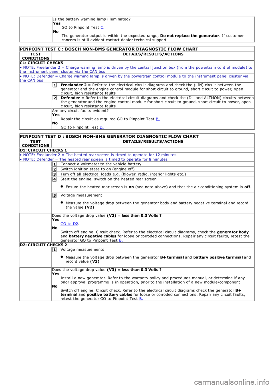
Is the bat tery warning lamp i ll uminated?YesGO t o Pi npoint Tes t C.NoThe generat or output is wit hi n t he expected range, Do not replace the generator. If cus tomerconcern i s s ti ll evident cont act dealer t echnical support
PINPOINT TEST C : BOSCH NON-BMS G ENERATOR DIAG NOSTIC FLOW CHART
T ESTCONDIT IONSDET AILS/RESULT S/ACT IONS
C1: CIRCUIT CHECKS
• NOTE: Freel ander 2 = Charge warni ng lamp is driven by t he cent ral juncti on box (from t he powert rain cont rol module) tot he ins trument panel clus ter via the CAN bus
• NOTE: Defender = Charge warning lamp i s dri ven by the powertrain control modul e t o the ins trument panel cl ust er viat he CAN busFreelander 2 = Refer t o t he elect rical circui t diagrams and check t he (LIN) ci rcuit bet ween thegenerat or and the engine control modul e for s hort ci rcuit t o ground, short ci rcuit to power, openci rcuit , hi gh res i st ance fault s
Defender = Refer to the el ect ri cal circuit di agrams and check the (D+ and ALTMON) circui ts bet weenthe generat or and t he engine control modul e for s hort circui t to ground, s hort circui t t o power, openci rcuit , hi gh res i st ance fault s
Are any circui t fault s evident?YesRepair t he circui t as required GO t o Pi npoi nt Tes t B.NoGO t o Pinpoint Tes t D.
PINPOINT TEST D : BOSCH NON-BMS GENERATOR DIAGNOSTIC FLOW CHART
T ESTCO NDIT IONSDET AILS/RESULT S/ACT IONS
D1: CIRCUIT CHECKS 1
• NOTE: Freel ander 2 = The heat ed rear s creen i s ti med t o operat e for 12 minutes• NOTE: Defender = The heat ed rear s creen is t imed to operate for 8 mi nutes
Connect a volt meter t o t he vehi cl e batt ery
Swit ch ignit ion s t at e t o on (engine off)
Turn off al l elect rical l oads e.g. (bl ower, radio, i nt eri or light s etc.)
Start the engine, s wit ch on the heat ed rear s creen
Ens ure the heated rear s creen is on (s ee note above) and t hat t he air condi ti oning s yst em is off.
Vol tage meas urement
Meas ure the volt age drop bet ween the generat or body and bat tery negat ive t ermi nal and recordthe value (V2)
Does t he volt age drop value (V2) = less than 0.3 Volts ?YesGO t o D2.NoSwit ch off engi ne. Ci rcuit check. Refer t o t he electrical ci rcuit diagrams, check the generator bodyand battery negative cables for loos e or corroded connecti ons . Repair any circuit fault s, retes t t hegenerat or GO t o Pi npoint Tes t B.D2: CIRCUIT CHECKS 2
Vol tage meas urement s
Meas ure the volt age drop bet ween the generat or B+ terminal and battery positive terminal andrecord value (V3)
Does t he volt age drop value (V3) = less than 0.3 Volts ?YesIns tal l a new generator. Refer to the warrant y policy and procedures manual, or determine if anyprior approval programme is i n operat ion, prior t o t he ins t al lat ion of a new modul e/componentNoSwit ch off engi ne. Ci rcuit check. Refer t o t he electrical ci rcuit diagrams check t he generator B+terminal and positive battery cables for l oose or corroded connect ions . Repai r any ci rcuit faul ts ,ret es t t he generator GO to Pi npoi nt Tes t B.
Page 1827 of 3229
Publi s hed: 11-May-2011
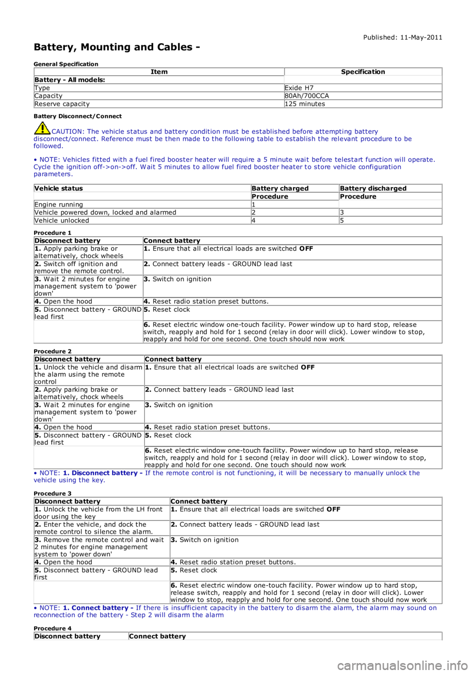
Battery, Mounting and Cables -
General SpecificationItemSpecification
Battery - All models:
TypeExide H7Capaci ty80Ah/700CCA
Res erve capacit y125 minutes
Battery Disconnect/C onnect
CAUTION: The vehicle s t atus and batt ery condit ion mus t be es t abl is hed before att empti ng bat t erydis connect/connect . Reference mus t be t hen made t o t he fol lowing table to es t abl is h t he rel evant procedure t o befol lowed.
• NOTE: Vehicles fit ted wit h a fuel fired boos t er heat er will requi re a 5 mi nute wait before tel es t art funct ion wi ll operate.Cycl e t he ignit ion off->on->off. W ai t 5 mi nutes t o all ow fuel fired boos t er heat er to s t ore vehicle confi gurati onparamet ers .
Vehicle statusBattery chargedBattery discharged
ProcedureProcedure
Engine runni ng1Vehicle powered down, l ocked and alarmed23
Vehicle unl ocked45
Procedure 1
Disconnect batteryConnect battery1. Apply parki ng brake oralt ernat ively, chock wheels1. Ens ure that all el ect ri cal loads are s wit ched O FF
2. Swit ch off i gni ti on andremove the remote cont rol.2. Connect bat t ery l eads - GROUND lead l ast
3. W ai t 2 mi nut es for enginemanagement sys tem t o 'powerdown'
3. Swit ch on ignit ion
4. Open t he hood4. Reset radi o s tat ion preset but tons .
5. Dis connect batt ery - GROUNDl ead firs t5. Reset clock
6. Reset elect ric window one-t ouch facili ty. Power window up t o hard s top, rel eas es wit ch, reapply and hol d for 1 s econd (relay i n door wil l cl ick). Lower window t o s top,reapply and hold for one s econd. One t ouch s hould now work
Procedure 2
Disconnect batteryConnect battery
1. Unlock t he vehi cl e and dis armt he alarm us ing t he remotecont rol
1. Ensure t hat al l el ect ri cal l oads are s wit ched OFF
2. Apply parki ng brake oralt ernat ively, chock wheels2. Connect batt ery l eads - GROUND l ead las t
3. W ai t 2 mi nut es for enginemanagement sys tem t o 'powerdown'
3. Swit ch on i gni ti on
4. Open t he hood4. Res et radio s t ati on pres et but tons .
5. Dis connect batt ery - GROUNDl ead firs t5. Res et cl ock
6. Res et el ect ri c window one-touch facil it y. Power window up to hard s top, rel eases wit ch, reappl y and hold for 1 s econd (rel ay in door wil l cl ick). Lower window t o s top,reapply and hol d for one s econd. One t ouch should now work
• NOTE: 1. Disconnect battery - If the remot e cont rol is not funct ioning, it will be necess ary to manual ly unlock thevehi cl e us ing t he key.
Procedure 3
Disconnect batteryConnect battery1. Unlock t he vehi cl e from the LH frontdoor us i ng the key1. Ens ure t hat al l electrical l oads are s wi tched OFF
2. Enter t he vehi cl e, and dock t heremote control to si lence the al arm.2. Connect batt ery leads - GROUND l ead las t
3. Remove t he remot e cont rol and wai t2 minutes for engi ne managements yst em to 'power down'
3. Swi tch on i gni ti on
4. Open t he hood4. Res et radio st ati on pres et but t ons .
5. Dis connect batt ery - GROUND leadfirst5. Res et cl ock
6. Res et el ect ri c wi ndow one-touch facil it y. Power wi ndow up to hard s t op,release s wit ch, reapply and hol d for 1 second (relay i n door wil l cl ick). Lowerwi ndow to s top, reapply and hold for one s econd. One t ouch s hould now work
• NOTE: 1. Connect battery - If there is ins uffi cient capacit y in the bat tery to di s arm the al arm, t he alarm may sound onreconnect ion of t he bat t ery - St ep 2 wi ll dis arm t he alarm
Procedure 4
Disconnect batteryConnect battery
Page 1828 of 3229
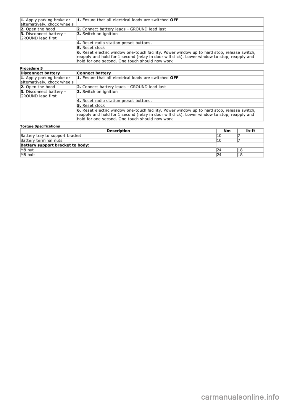
1. Apply parki ng brake oralt ernat ively, chock wheels1. Ens ure t hat al l elect rical l oads are s wit ched OFF
2. Open t he hood2. Connect batt ery leads - GROUND l ead las t3. Dis connect batt ery -GROUND lead firs t3. Swit ch on i gni ti on
4. Res et radio s t ati on pres et but tons .
5. Res et cl ock
6. Res et el ect ri c window one-touch facil it y. Power wi ndow up to hard s t op, release swit ch,reapply and hol d for 1 s econd (relay i n door wil l cl ick). Lower window t o s top, reapply andhold for one s econd. One t ouch s houl d now work
Procedure 5
Disconnect batteryConnect battery1. Apply parki ng brake oralt ernat ively, chock wheels1. Ens ure t hat al l elect rical l oads are s wit ched OFF
2. Open t he hood2. Connect batt ery leads - GROUND l ead las t
3. Dis connect batt ery -GROUND lead firs t3. Swit ch on i gni ti on
4. Res et radio s t ati on pres et but tons .
5. Res et cl ock
6. Res et el ect ri c window one-touch facil it y. Power wi ndow up to hard s t op, release swit ch,reapply and hol d for 1 s econd (relay i n door wil l cl ick). Lower window t o s top, reapply andhold for one s econd. One t ouch s houl d now work
Torque SpecificationsDescriptionNmlb-ft
Batt ery tray to support bracket107
Batt ery terminal nut s107Battery support bracket to body:
M8 nut2418
M8 bol t2418
Page 1829 of 3229
Publi s hed: 11-May-2011
Battery, Mounting and Cables - Battery and Cables
Des cript ion and Operat ion
COMPONENT LOCATION
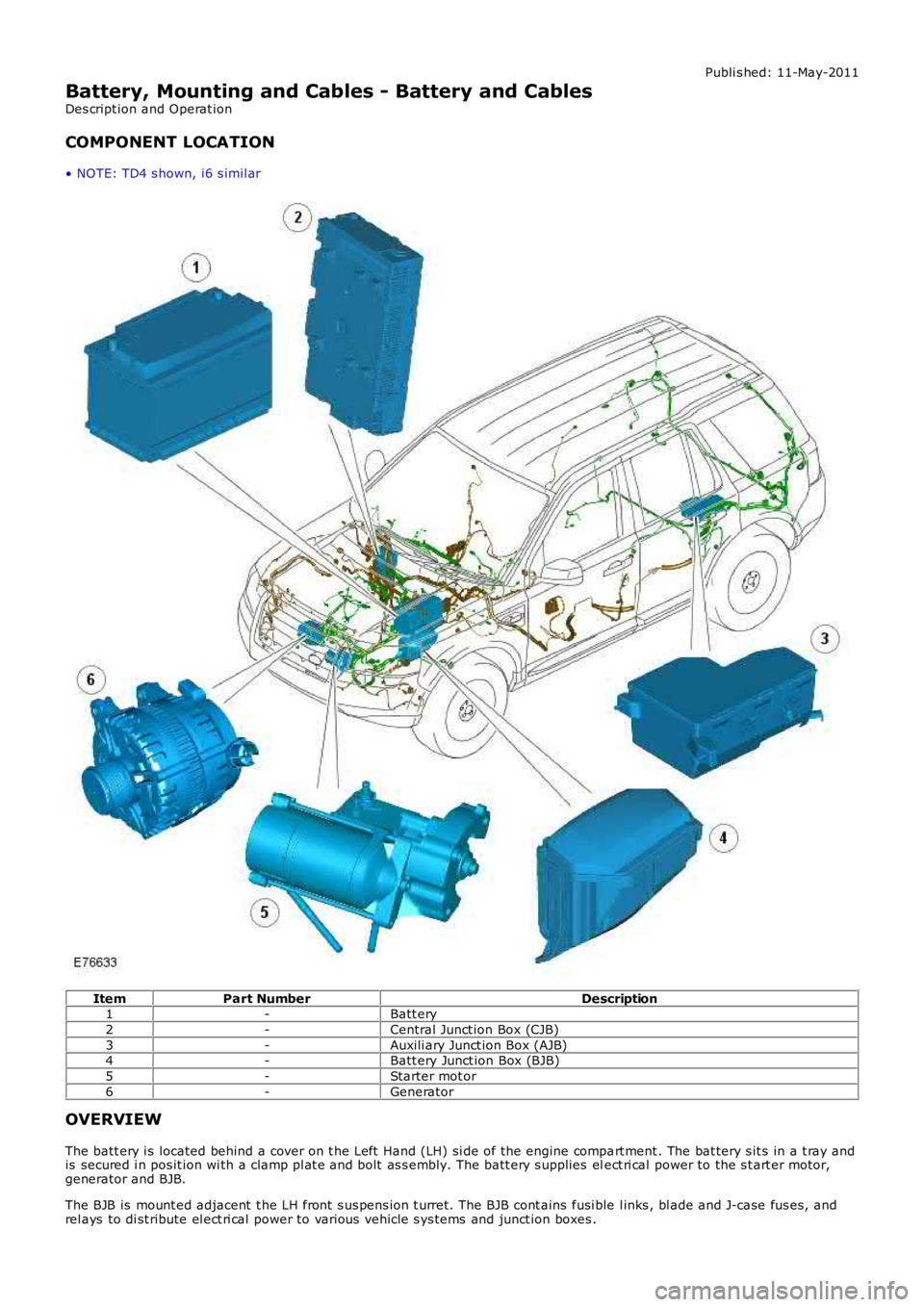
• NOTE: TD4 s hown, i6 s imil ar
ItemPart NumberDescription1-Batt ery
2-Central Junct ion Box (CJB)
3-Auxili ary Junct ion Box (AJB)4-Batt ery Junct ion Box (BJB)
5-Starter mot or
6-Generator
OVERVIEW
The batt ery i s located behind a cover on t he Left Hand (LH) si de of the engine compart ment . The bat tery s it s in a t ray andis secured i n pos it ion wi th a clamp pl at e and bolt as s embly. The batt ery s upplies elect ri cal power to the s t art er motor,generator and BJB.
The BJB is mount ed adjacent t he LH front s us pens ion t urret. The BJB cont ains fusi ble l inks , bl ade and J-case fus es, andrel ays to di st ribute el ect ri cal power to various vehicle s ys tems and junct ion boxes .
Page 1830 of 3229
• NOTE: The fus i bl e l inks are mount ed on t he inboard s i de of the BJB behind a series of removable covers .
The CJB is mount ed behind t he glovebox and recei ves it s main power s uppl y from the BJB. In addi ti on to cont aining bl adefus es , the CJB i s t he main controll er for a number of vehicle s ys t ems. Thes e functi ons are out li ned in t he rel evant s ect ionsof thi s manual .
The AJB is locat ed beneat h t he luggage compartment carpet , adjacent t he spare wheel wel l. The AJB i s a modular des ign,and compris es up t o 3 individual elements depending on vehicle specificati on. The AJB cont ains bl ade and J-cas e fuses ,and rel ays to di st ribute el ect ri cal power to sys t ems used at the rear of t he vehi cle. The AJB receives it s mai n power s upplyfrom the BJB.
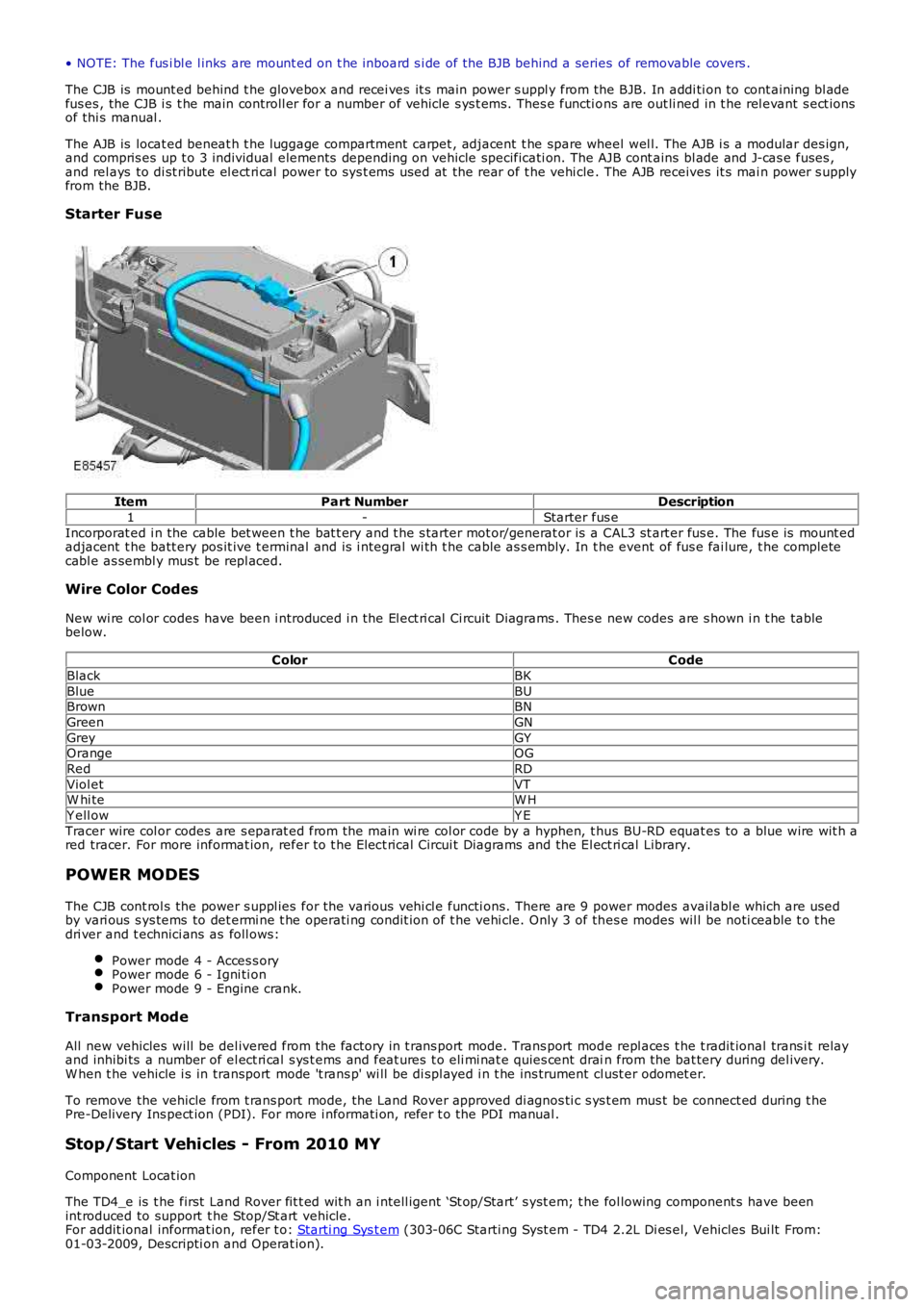
Starter Fuse
ItemPart NumberDescription
1-Starter fus e
Incorporat ed i n the cable bet ween t he bat t ery and t he s tarter mot or/generat or is a CAL3 st art er fus e. The fus e is mount edadjacent t he batt ery pos it ive t erminal and is i ntegral wi th t he cable as s embly. In the event of fus e fai lure, t he completecabl e as sembl y mus t be repl aced.
Wire Color Codes
New wi re col or codes have been i ntroduced i n the El ect ri cal Ci rcuit Di agrams . Thes e new codes are s hown i n t he tablebelow.
ColorCode
BlackBK
BlueBUBrownBN
GreenGN
GreyGYOrangeOG
RedRD
Viol etVTW hi teW H
Y ell owY E
Tracer wire col or codes are s eparat ed from the main wi re col or code by a hyphen, t hus BU-RD equat es to a blue wire wit h ared tracer. For more informat ion, refer to t he Elect rical Circui t Diagrams and the El ect ri cal Library.
POWER MODES
The CJB cont rol s the power s uppl ies for the vari ous vehi cl e functi ons. There are 9 power modes availabl e which are usedby vari ous s ys tems to det ermi ne t he operati ng condit ion of t he vehi cle. Only 3 of thes e modes wil l be noti ceable t o t hedri ver and t echnici ans as foll ows:
Power mode 4 - Acces s oryPower mode 6 - Igni ti onPower mode 9 - Engine crank.
Transport Mode
All new vehicles will be del ivered from the factory in t rans port mode. Trans port mode repl aces t he t radit ional trans i t relayand inhibi ts a number of el ect ri cal s ys t ems and feat ures t o eli mi nat e quies cent drain from the bat tery during del ivery.W hen t he vehicle i s in transport mode 't rans p' wi ll be di spl ayed i n t he ins trument cl ust er odomet er.
To remove the vehicle from t rans port mode, the Land Rover approved di agnos ti c s ys t em mus t be connect ed during t hePre-Delivery Ins pect ion (PDI). For more i nformati on, refer t o the PDI manual .
Stop/Start Vehicles - From 2010 MY
Component Locat ion
The TD4_e is t he first Land Rover fit t ed wit h an i ntell igent ‘St op/Start’ s yst em; t he fol lowing component s have beenint roduced to support t he Stop/St art vehicle.For addit ional informat ion, refer t o: Starti ng Sys t em (303-06C Starti ng Syst em - TD4 2.2L Di es el, Vehicles Bui lt From:01-03-2009, Descripti on and Operat ion).