LAND ROVER FRELANDER 2 2006 Repair Manual
Manufacturer: LAND ROVER, Model Year: 2006, Model line: FRELANDER 2, Model: LAND ROVER FRELANDER 2 2006Pages: 3229, PDF Size: 78.5 MB
Page 1811 of 3229
Publi s hed: 11-May-2011
Battery and Charging System - General Information -
Vehicle Jump (Emergency) Starting - Using another vehicle
• W ARNINGS:
During normal us e, bat t eries emi t expl osi ve hydrogen gas suffi ci ent t o cause severe expl os i ons and capabl e ofcaus ing serious injury - keep s parks and naked li ght s away from the engine compart ment.
DO NOT at tempt t o s tart the di s abl ed vehi cl e i f it is sus pect ed t hat t he elect rolyte in the bat tery is frozen.
Suit able eye prot ect ion must be worn when working i n t he vicinit y of t he bat t ery.
Take care when working near rot at ing parts of t he engine.
Prior to att empti ng to st art t he dis abled vehicle, ens ure t hat the parki ng brake i s appl ied or s uit abl y chock t hewheels . Ens ure that 'P' - PARK - Aut omati c Trans mis s ion or NEUTRAL - Manual Trans mi ss i on is s elect ed.
• CAUTIO NS:
Ens ure t hat al l electrical l oads are s wi tched OFF pri or to connect ing boos ter cabl es and dis connect boos t er cablespri or to us ing el ect ri cal equipment .
Ens ure t hat the bat tery of the DO NOR vehicle is of 12 volt capaci ty and that all electrical loads on t he dis abl edvehi cl e are s wit ched O FF prior t o connecti ng boost er cables .
Ens ure t hat there is no phys ical contact between t he donor and di sabl ed vehi cl es other than t he boost er cabl es .
• NOTE: Disconnect battery: If t he remote control hands et is not functi oning, it wi ll be neces s ary t o manuall y unlock thevehi cl e us ing t he key.
Carry out the following operation in the sequence given:
1. Connect one end of the Red (+) boos t er cable to t he pos it ive (+) batt ery terminal of the DISABLED vehicle.2. Connect t he other end of the Red (+) boos ter cable t o t he posi ti ve (+) batt ery t erminal of t he DONOR vehicle.
3. Connect one end of the Black (-) boos ter cabl e t o t he Ground (-) bat t ery t ermi nal of t he DONOR vehi cle.
4. Connect t he other end of the Bl ack (-) boost er cabl e t o a good eart h point e.g. unpainted metal s urface or enginemounti ng at leas t 0.5 m (20.0 i n) from t he batt ery or fuel l ines on t he DISABLED vehi cle.
5. Start the engi ne of the DO NOR vehicle and al low it t o i dl e for a few minut es .6. Start the engi ne of the DISABLED vehicle.
7. All ow engines of both vehicles t o i dle for a few mi nut es t hen swi tch off the engine of t he DONO R vehicle.
8. Dis connect t he Black (-)boos t er cable from t he eart h point of t he PREVIO USLY DISABLED vehi cl e.9. Dis connect t he Black (-)boos t er cable from t he batt ery of t he DONO R vehicle.
10. Dis connect the Red (+) boos t er cable from t he batt ery of t he DONOR vehi cl e.
11. Dis connect the Red (+) boos t er cable from t he batt ery of t he PREVIOUSLY DISABLED vehi cl e.
Vehicle Jump (Emergency) Starting - Using a Slave Battery/Starting Aid
• W ARNINGS:
During normal us e, bat t eries emi t expl osi ve hydrogen gas suffi ci ent t o cause severe expl os i ons and capabl e ofcaus ing serious injury - keep s parks and naked li ght s away from the engine compart ment.
DO NOT at tempt t o s tart the di s abl ed vehi cl e i f it is sus pect ed t hat t he elect rolyte in the bat tery is frozen.
Suit able eye prot ect ion must be worn when working i n t he vicinit y of t he bat t ery.
Take care when working near rot at ing parts of t he engine.
Prior to att empti ng to st art t he dis abled vehicle, ens ure t hat the parki ng brake i s appl ied or s uit abl y chock t hewheels . Ens ure that 'P' - PARK - Aut omati c Trans mis s ion or NEUTRAL - Manual Trans mi ss i on is s elect ed.
• CAUTIO NS:
Ens ure t hat al l electrical l oads are s wi tched OFF pri or to connect ing boos ter cabl es and dis connect boos t er cablespri or to us ing el ect ri cal equipment .
Ens ure t hat the s l ave bat tery/s tarti ng aid are of 12 volt capacit y and t hat al l elect rical l oads on the di sabl ed vehi cl eare swi tched OFF prior t o connecti ng boos t er cables .
Page 1812 of 3229

Carry out the following operation in the sequence given:
1. Connect t he end of the Red (+) boos ter cable t o t he posi ti ve (+) batt ery t erminal vehicle of the vehicle.
2. Connect t he end of the Bl ack (-) boost er cabl e to a good eart h point e.g. unpainted metal s urface or engine mount ingat leas t 0.5 m (20.0 i n) from t he batt ery or fuel l ines on t he vehicle.
3. Start the engi ne of the vehicle and al low it t o idl e.
4. Dis connect t he Black (-) boos ter cabl e from the earth poi nt of t he vehicle.Di sconnect t he Red (+) boos t er cable from t he batt ery t erminal of t he vehicle.
Page 1813 of 3229
Publi shed: 14-Jul-2011
Battery and Charging System - General Information - Battery Care
Des cript ion and Operat ion
12V LEAD ACID BATTERY CARE MANUAL FOR DEALER / RETAILER USE
1. INTRODUCTION
2. GENERAL RULES FOR BATTERY CARE
3. EQU IPMENT (MINIMU M STANDARD)
4. HEALTH AND SAFETY PRECAUTIONS
5. DETERMINING BATTERY CONDITION
6. BATTERY CHARGING AND MAINTENANCE
7. CHARGING SYSTEM TEST AND DIAGNOSIS
8. VEHICLE QUIESCENT CURRENT TESTING
APPENDIX A: BATTERY TEST PROCESS
APPENDIX B: BATTERY REPORT FORM - IN SERVICE BATTERIES ONLY
1. INTRODUCTION
This publi cat ion s ets out , for t he benefit of dealers / ret ailers worl dwide, requirement s for the care and maint enance ofbatt eri es , from the vehicles hand-over to the dealer / retail er to the handover t o the cus t omer or i n t he cas e of a sparepart batt ery from i s delivery to the dealer / retail er to it s fi tment t o a cus tomer vehicle.
It appl ies t o all t ypes of 12 volt Lead Acid Bat teries us ed, whet her they are convent ional fl ooded t echnology or Abs orbedGlas s Mat (AGM) technol ogy and als o applies to bot h Pri mary and Secondary or Auxi li ary Bat teri es.
The clearl y lai d out and ill ust rat ed s ect ions guide dealers / ret ail ers t hrough each st age of the vehicl es or s pare partsreceipt , st orage, pre-del ivery and cus tomer hand-over. This publi cat ion can be us ed as a gui de to the handli ng and care ofbatt eri es in s ervi ce. It is vi tal t o appreci ate that unles s each proces s i s ri gorousl y appl ied on al l vehi cl es, t he cust omer wil lreceive a vehicl e wit h a bat tery or a s pare part bat t ery which will not provide a s at is fact ory s ervi ce life.
It is very import ant that all t est s quoted throughout this publ icat ion are adhered to. If t hey are appli ed incorrect lybatt eri es could be s crapped unneces s ari ly. Refer to the bat tery tes t ing s ect ion for detail ed informat ion.
It is equally important therefore to not e t he fol lowing key point s :
Mos t new vehi cl es leave t he factory wi th ei ther a t rans it relay i ns t alled and/or have a trans it mode programmedint o t he vehi cl e cont rol modules . The t rans it rel ay mus t be removed and t he t rans it mode di sabled (whereappl icable) us ing an approved diagnost ic sys tem, NOT MO RE T HAN 24 HOURS before t he cust omer t akes deli very.12 Volt Lead Acid Bat teries rely on i nternal chemical proces s es to create a vol tage and deli ver current. Theseprocess es and t he int ernal chemi cal s truct ure of the bat tery can be damaged i f the bat tery is allowed t o di schargeover a number of weeks / months , or is left i n a di scharged s t at e for a lengt hy ti me peri od. For t hi s reas on t hebatt ery mus t be t es ted / re-charged i f neces sary every mont h, and MUST BE re-charged after every t hree mont hperi od of st orage. Refer to the vehicle st orage manual and updat e t he vehi cl e his t ory s heet.Under no ci rcums tances should the bat tery be dis connected wit h the engi ne running becaus e under thes e condi ti onst he alt ernator can give a very high output volt age. This hi gh t rans ient vol tage wi ll damage t he electroni ccomponents in t he vehicle. Loos e or i ncompl et e bat tery connect ions may al s o caus e high transi ent volt age.On vehicles wi th conventi onal ignit ion keys , thes e mus t not be left in t he i gni ti on lock barrel when the t rans it relayhas been removed, ot herwi se qui escent current wi ll increas e and t he bat t ery wi ll discharge more rapi dl y.Two t ypes of Lead acid bat teri es are us ed; s tandard Fl ooded t ype and AGM (Absorbed Glas s Mat) or VRLA (Valveregulat ed Lead Aci d) types. AGM batt eries offer i mproved res is t ance t o cycl ing as seen i n s top st art appli cat ions .AGM Bat teries are ful ly s ealed and cannot have t he electrolyte level t opped up.
Dealers and retailers involved in the storage, handling of vehicles and spare parts batteries have a responsibility toensure that only vehicles and spare parts having a fully satisfactory battery may be processed further through thedistribution selling chain.
• NOTE: It is very important that t est proces s es quot ed t hroughout t hi s publicati on are adhered to.
If they are not adhered t o correct ly bat teries could be scrapped unneces saril y or a batt ery wit h an is s ue remains in use.Refer t o t he bat t ery t est ing s ecti on for detai led i nformat ion.
2. GENERAL RULES FOR BATTERY CARE
Frequency of Battery Cond ition Checks.
Any batt ery i n s torage whether it i s in a vehi cle or i n s pare part s i nventory mus t have it s charge s tat us checked every 30days as des cri bed in Appendix A, and mus t be recharged every 90 days as des cribed i n t he "Bat tery Charging andMaint enance" secti on of thi s manual.
Dealer Demonstration Vehicles
Page 1814 of 3229
Due t o t he high depth of di scharge a deal er demons trati on vehi cl e batt ery may experience, bat teri es t hat are fi tt ed t ovehi cl es us ed as deal er demons trati on vehi cl es mus t be connected t o a power s upply / charger capable of deli vering 50Amps or more whil st the vehicle is being demons trated and t he engine i s not running. Thi s wi ll prevent the bat tery frombeing damaged from "energy t hroughput " wear out during a demons t rat ion.
Software Reflash, SDD work or Ig nition On related Workshop Activities.
Due t o t he high elect rical current demand and high dept h of Dis charge that can occur duri ng vehi cl e s oft ware re-flas hact ivi ti es , SDD work or igni ti on on rel at ed work in the workshop, vehi cl es that are undergoi ng s uch act ivit ies MUST havet he elect rical s ys tem on t he vehi cl e s upported wi th a power supply / charger / vehicle maintai ner capabl e of deliveri ng 50Amps or more.
Jump Starting New vehicles Before They Have Been Delivered to the Customer.
It is t he dealer / ret ailers res ponsi bili ty to ens ure the bat tery is not al lowed t o go flat by fol lowi ng the i nst ruct ionsand process es defi ned in this manual .However i f ci rcums tances dictat e t hat a new vehi cl e mus t be jump s t arted due to a flat bat t ery whil s t the vehicle isin the dealer / retail ers care, t he batt ery on this vehi cl e mus t be repl aced wi th a new one prior to del ivery to thecus t omer at the dealer / retail ers l iabil it y.The vehi cl e s houl d als o undergo inves t igati on as t o why t he batt ery went flat.Do not connect the jump s t art ing cable t o t he negat ive (-) terminal of the bat tery. Al ways connect t o t herecommended eart hing point . As defined i n t he owners handbook or s ervice document ation for t hat vehi cl e.
Jump Starting or Boost Charging Vehicles in Service
Do not connect the jump s t art ing cable t o t he negat ive (-) terminal of the bat tery. Al ways connect t o t he recommendedeart hing point . As defined i n t he owners handbook or s ervice document ati on for t hat vehi cl e.
Charging AG M Batteries
AGM bat teries mus t not be charged wit h volt ages above 14.8 Vol ts . Doing so wil l damage t hem.
Testing AGM Batteries
Midt ronics 393, 394, 493 and 494 t es ters are not capabl e of tes ti ng AGM bat teries . Doing s o can give an incorrect res ult .
W hen i t is necess ary to tes t an AGM bat tery us e t he Midt ronics EXP1080 tes ter or t he GR1 Diagnost ics Charger.
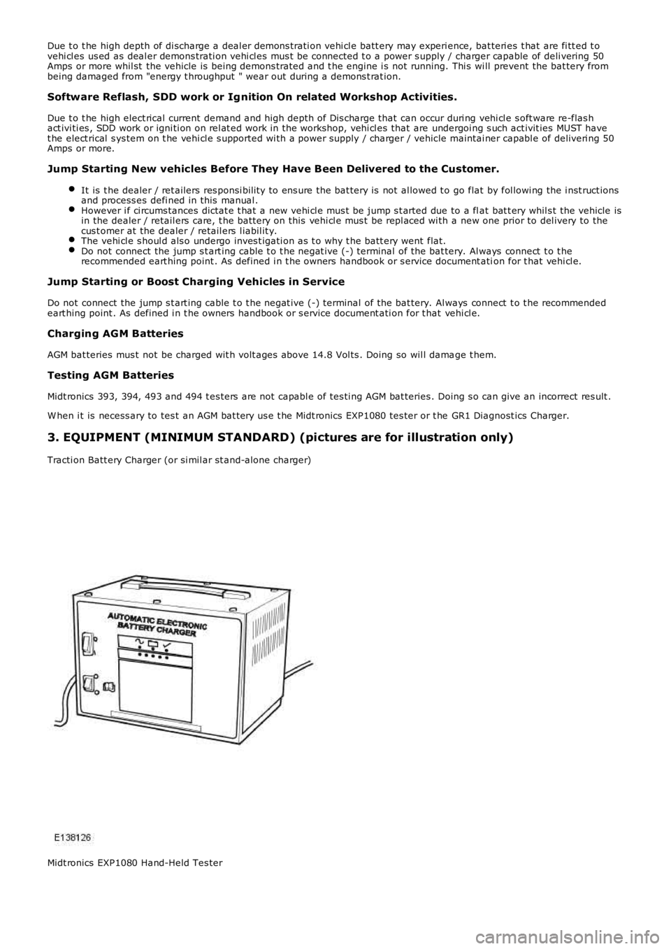
3. EQUIPMENT (MINIMUM STANDARD) (pictures are for illustration only)
Tracti on Batt ery Charger (or si mil ar st and-alone charger)
Midt ronics EXP1080 Hand-Held Tes ter
Page 1815 of 3229
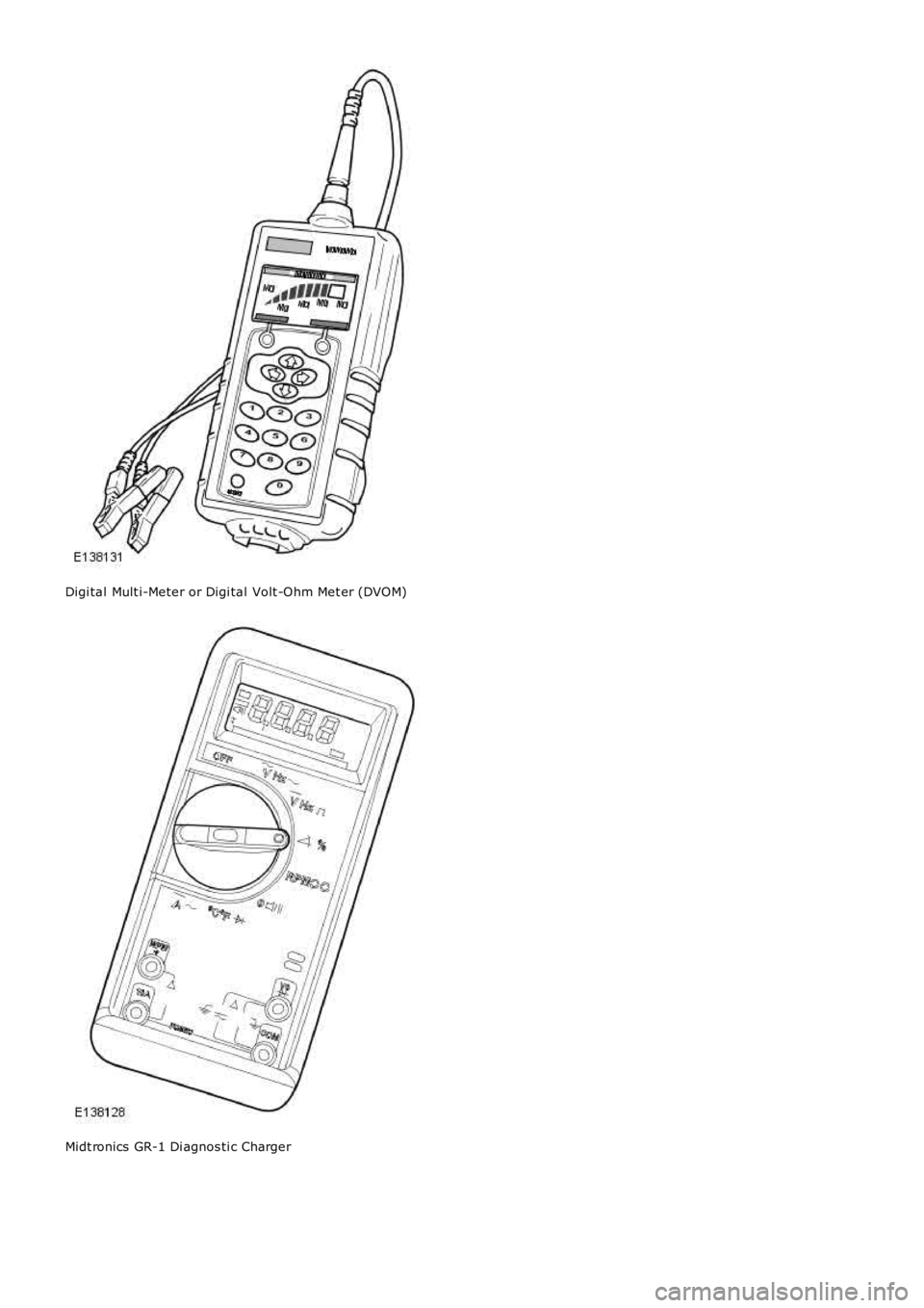
Digi tal Mult i-Meter or Digi tal Volt -Ohm Met er (DVOM)
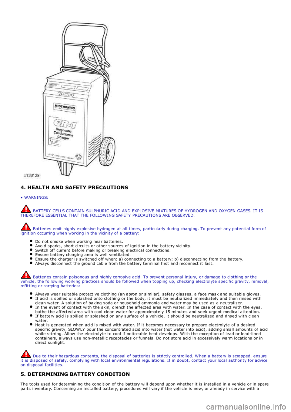
Midt ronics GR-1 Di agnos ti c Charger
Page 1816 of 3229
4. HEALTH AND SAFETY PRECAUTIONS
• W ARNINGS:
BATTERY CELLS CONTAIN SULPHURIC ACID AND EXPLOSIVE MIXTURES OF HY DROGEN AND OXY GEN GASES. IT ISTHEREFORE ESSENTIAL THAT THE FOLLOW ING SAFETY PRECAUTIONS ARE OBSERVED.
Bat teri es emit hi ghl y explos ive hydrogen at all ti mes , parti cul arl y during chargi ng. To prevent any potent ial form ofignit ion occurring when worki ng in the vi ci nit y of a batt ery:
Do not s moke when worki ng near bat teri es.Avoi d s parks , short ci rcuit s or other s ources of i gni ti on in the bat tery vicinit y.Swit ch off current before maki ng or breaki ng electrical connect ions .Ensure batt ery chargi ng area i s well venti lated.Ensure t he charger i s s wit ched off when: a) connect ing t o a bat tery; b) di sconnect ing from the bat tery.Always dis connect t he ground cabl e from the bat tery terminal fi rs t and reconnect i t las t.
Bat teri es cont ain poi sonous and highly corros ive acid. To prevent pers onal injury, or damage to cl ot hing or t hevehi cl e, the foll owing worki ng practi ces s hould be foll owed when t opping up, checking el ect rol yt e s peci fi c gravit y, removal,refit ti ng or carrying bat teries :
Always wear s uit abl e prot ect ive clot hing (an apron or s imilar), s afet y glas s es , a face mas k and s uit abl e gloves.If acid is s pil led or s plas hed onto cl ot hing or t he body, i t mus t be neut ral ized immediatel y and then rins ed wi thclean wat er. A s olut ion of baking s oda or hous ehol d ammoni a and water may be used as a neut ral izer.In the event of cont act wi th the s kin, drench t he affect ed area wit h water. In the cas e of cont act wi th the eyes ,bathe t he affect ed area wit h cool clean wat er for approximat ely 15 minutes and s eek urgent medical att ent ion.If bat tery aci d i s s pi ll ed or spl ashed on any s urface of a vehi cl e, it s houl d be neutrali zed and rins ed wi th cl eanwater.Heat is generat ed when aci d i s mixed wi th water. If i t becomes neces s ary t o prepare electrolyte of a desi reds pecific gravi ty, SLOW LY pour t he concent rat ed acid i nto wat er (not wat er i nto aci d), addi ng s mall amounts of acidwhil e s ti rring. All ow t he electrol yte to cool if noti ceable heat develops. W it h t he excepti on of lead or lead-linedcont ainers , always us e non-met all ic receptacles or funnels . Do not s t ore acid in exces s ively warm locat ions or i ndirect s unli ght .
Due t o t heir hazardous content s, t he dis pos al of batt eri es is s t ri ct ly cont roll ed. W hen a batt ery is s crapped, ens ureit i s dis pos ed of safel y, compl yi ng wit h l ocal envi ronment al regul ati ons . If in doubt, contact your l ocal aut hori ty for advi ceon dis pos al faci li ti es .
5. DETERMINING BATTERY CONDITION
The t ool s used for determining the condit ion of t he bat t ery wi ll depend upon whet her i t is i nst all ed in a vehi cl e or in s parepart s inventory. Concerning an i nst all ed batt ery, procedures wil l vary if t he vehi cle i s new, or al ready in s ervice wi th a
Page 1817 of 3229
cus t omer.
• NOTE: The t erm `New Vehicle' refers t o a vehicle at any part of the deli very proces s from l eavi ng the factory to arri vingat a port of ent ry, deal ers hip, ret ailer, including any s t orage facil it ies en route or a vehi cl e being s t ored pri or to sal e atdeal ers hip / ret ai ler.
• NOTE: Mi dt roni cs 393, 394. 493 and 494 t es ters mus t not be us ed t o t est AGM batt eri es as thes e t est ers are not capableof correctl y t es t ing AGM batt eries and can gi ve an incorrect resul t. For AGM batt ery tes ti ng us e the EXP1080 t es t er or t heGR1 Di agnos ti cs charger.
NEW VEHICLES
A Mi dtroni cs tes t er s hould be us ed t o as s es s t he condi ti on of the bat tery for new vehicles . The t es t resul ts s hould berecorded on t he St orage His t ory Sheet (s ee Vehicle St orage manual).
Scenario 1 - Dealership / Retailer (Responsibility: Dealer / Retailer)
1. W i thin 24 hours of arrival at the dealer / retail er proceed as foll ows:
Perform a Mi dt roni cs bat tery tes t (See Appendix A.)Carry out the recommended act ions accordi ngl y.
2. If t he Mi dt roni cs res ul t is "Good Bat tery" t he vehi cle may be s tored.
For al l new vehi cl es in st orage t he t rans it rel ay MUST be fit ted, or t he Transi t Mode enabl ed where us ed. Forvehi cl es wit hout a t ransi t rel ay or a Trans it Mode, the bat tery negat ive cable MUST BE DISCONNECTED from thebatt ery.
3. The bat t ery mus t be t est ed and/or re-charged every mont h and MUST be re-charged aft er every t hree mont h period.
4. Record your t est res ul ts on the St orage Hi s tory Sheet (see Vehi cl e Storage Manual ) to indicate when a re-charge wil l beneces s ary.
Scenario 2 - Delivery to the Customer (Responsibility: Dealer / Retailer)
• NOTE: It is es s ent ial t hat t he followi ng act ions are conducted i n t he 24 hours prior to the agreed hand over t ime:
1. Perform a Midt ronics Bat tery tes t (See Appendix A).
2. Carry out the recommended acti ons accordingl y.
3. The vehi cl e s houl d only be releas ed to the cus tomer i f Midt ronics has t es t ed t he batt ery as "Good Batt ery"
Spare Part Batteries
Lead aci d batt eri es wil l, as a resul t of nat ural chemical proces s es , s lowl y s el f discharge thems elves over a peri od of ti me(even when open circui t and no electrical load applied).
In the cas e of s pare part s bat teri es, a Midt ronics t est er s hould be us ed to as s es s the condit ion of new s pare partsbatt eri es .
The batt eri es must be st ored such t hat t hey cannot get wet and are not i n direct s unli ght .
Any batt eri es which are dropped must be scrapped. Thi s applies even i f no ext ernal damage is apparent .
Scenario 1 - Spare Part Batteries Within Dealer Stock But Not Yet Fitted To A Vehicle (Responsibility:
Dealer / Retailer)
1. For a bat t ery i n the Deal er parts or i n ready t o us e s t ock but not yet fit t ed to a vehi cl e t he fol lowing rules must befol lowed:
Check t he batt ery condit ion on recei pt by performing a Midt ronics bat tery tes t (See Appendix A).Batt eri es should onl y be returned t o s t orage if t he Mi dtroni cs tes ter i ndi cat es "Good Bat tery".The batt ery condit ion s houl d be rechecked every 30 days by performing a Midt ronics batt ery tes t (See Appendix A).If required bat teries s hould be recharged as des cri bed in t he "Batt ery Chargi ng and Maint enance" s ecti on of thi smanual.
2. 2 All bat teries mus t be cont rol led vi a a FIFO (Fi rs t In First Out ) process to ens ure aged bat teries are not hel d and t hebatt eri es are not all owed to age unnecess ari ly.
VEHICLES IN SERVICE
The Midt ronics hand-held tes ter or t he Midt ronics Di agnos ti c Charger are t he preferred tools to as s es s bat t ery condi ti on forvehi cl es in service. The t es t res ult s s houl d be recorded on the In-Servi ce Bat t ery Report Form (See Appendix B).
Midtronics Testing - In-Service Testing Only
• NOTE: The batt ery s urface charge mus t be removed before t his t est i n accordance with the procedure in Appendi x A.Ensure t hat t he batt ery terminal connect ors are clean. W hen connecti ng t he Midt ronics t est ing equipment , connect the REDclip to the pos it ive (+) batt ery terminal fi rs t, and t hen connect the BLACK cl ip t o t he negat ive (-) bat tery t ermi nal . Rockt he cl ips backward and forward to ens ure a good connecti on to the bat tery.
1. Perform a Midt ronics bat tery tes t (See Appendix A).
2. Carry out the recommended acti ons accordingl y.
Page 1818 of 3229
6. BATTERY CHARGING AND MAINTENANCE
BATTERY CHARGING
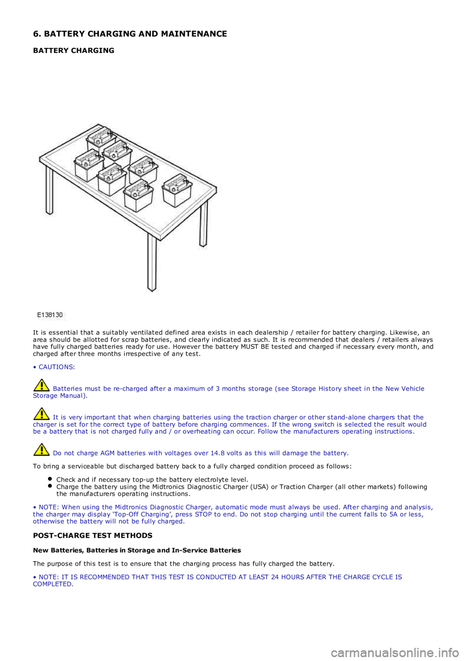
It is es s ent ial t hat a sui tably vent ilat ed defi ned area exis ts in each dealers hip / ret ailer for bat tery charging. Li kewis e, anarea s hould be al lot ted for s crap batt eries , and clearl y indicat ed as s uch. It is recommended t hat dealers / ret ail ers al wayshave full y charged batt eri es ready for us e. However t he bat t ery MUST BE tes ted and charged i f neces sary every mont h, andcharged aft er three months i rres pecti ve of any t es t.
• CAUTIO NS:
Bat teri es mus t be re-charged aft er a maximum of 3 mont hs st orage (s ee Storage His tory s heet i n t he New VehicleStorage Manual ).
It is very important t hat when chargi ng bat t eries us ing the t racti on charger or ot her s t and-alone chargers t hat thecharger i s s et for t he correct t ype of bat tery before chargi ng commences . If t he wrong swi tch i s s elected t he res ult woul dbe a bat tery that i s not charged full y and / or overheat ing can occur. Fol low the manufact urers operat ing ins truct ions .
Do not charge AGM bat t eries wit h vol tages over 14.8 volt s as t hi s wi ll damage the bat tery.
To bri ng a s ervi ceable but di scharged batt ery back t o a full y charged condit ion proceed as follows :
Check and i f neces s ary t op-up t he batt ery el ect rolyt e level.Charge t he batt ery us ing the Mi dtroni cs Diagnos t ic Charger (USA) or Tract ion Charger (all other market s) foll owingt he manufact urers operati ng ins t ructi ons .
• NOTE: W hen us ing the Mi dtroni cs Diagnost ic Charger, aut omati c mode mus t always be us ed. Aft er chargi ng and anal ysi s,t he charger may di s pl ay ‘Top-Off Charging’, pres s STOP t o end. Do not s top chargi ng unt il t he current falls to 5A or les s,otherwis e t he batt ery wi ll not be ful ly charged.
POST-CHARGE TEST METHODS
New Batteries, Batteries in Storage and In-Service Batteries
The purpos e of thi s tes t is to ens ure that t he chargi ng process has full y charged the bat tery.
• NOTE: IT IS RECOMMENDED THAT THIS TEST IS CO NDUCTED AT LEAST 24 HOURS AFTER THE CHARGE CY CLE ISCOMPLETED.
Page 1819 of 3229
CAUTION: DO NOT connect the tes ter t o any other circui t or chas si s point .
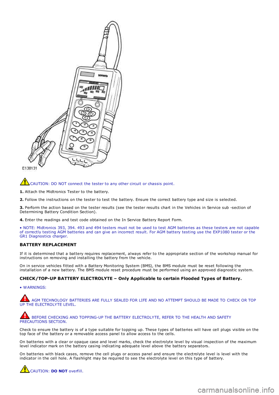
1. Att ach the Midtronics Test er to the bat tery.
2. Fol low the i nst ruct ions on t he tes t er t o t est the bat tery. Ens ure t he correct batt ery type and s ize i s s elect ed.
3. Perform the acti on based on the t es ter res ult s (s ee the t es ter res ult s chart i n the Vehi cl es in Servi ce s ub -s ecti on ofDetermini ng Batt ery Condit ion Secti on).
4. Ent er the readings and t es t code obtained on the In Servi ce Bat tery Report Form.
• NOTE: Mi dt roni cs 393, 394. 493 and 494 t es ters mus t not be us ed t o t est AGM batt eri es as thes e t est ers are not capableof correctl y t es t ing AGM batt eries and can gi ve an incorrect resul t. For AGM batt ery tes ti ng us e the EXP1080 t es t er or t heGR1 Di agnos ti cs charger.
BATTERY REPLACEMENT
If it is det ermined t hat a bat tery requires repl acement, al ways refer t o t he appropri at e s ecti on of the works hop manual forins t ructi ons on removing and i nst all ing t he batt ery from t he vehi cl e.
On i n s ervice vehicles fit ted wit h a Bat tery Monit oring Sys tem (BMS), t he BMS module must be res et foll owing t heins t al lat ion of a new bat tery. The BMS module reset procedure must be performed us ing an approved diagnost ic sys tem.
CHECK/TOP-UP BATTERY ELECTROLYTE – Only Applicable to certain Flooded Typ es of Battery.
• W ARNINGS:
AGM TECHNOLOGY BATTERIES ARE FULLY SEALED FOR LIFE AND NO ATTEMPT SHOULD BE MADE TO CHECK OR TOPUP THE ELECTROLY TE LEVEL.
BEFORE CHECKING AND TOPPING-UP THE BATTERY ELECTROLY TE, REFER TO THE HEALTH AND SAFETYPRECAUTIONS SECTION.
Check t o ens ure t he batt ery is of a t ype s uit abl e for t oppi ng up. Thes e t ypes of batteri es wil l have cell pl ugs vi si ble on thet op face of the bat tery or a removable acces s panel t o all ow acces s t o t he cel ls .
On bat teries wi th a cl ear or opaque cas e and l evel marks, check the el ect rolyt e level by vis ual i nspecti on of the maxi mumlevel indicator mark on t he batt ery cas ing i ndi cat ing adequat e l evel above the bat tery separat ors .
On bat teries wi th bl ack cas es, remove the cell pl ugs or acces s panel and ens ure the el ect rol yt e l evel is level wi th theindicat or i n t he cel l hol e. A flas hl ight may be requi red to s ee t he electrolyt e level on thi s type of batt ery.
CAUTION: DO NOT overfil l.
Page 1820 of 3229
If the el ect rolyt e level is l ow, top-up usi ng dis t ill ed water.
Maint enance free and Valve Regulat ed (AGM) bat teries are s eal ed and therefore cannot be topped up.
CHARGING SYSTEM TEST AND DIAGNOSIS
For al l vehi cl es , refer to the Chargi ng Syst em - Diagnos i s and Tes t ing i n s ect ion 414-00 of the W orks hop Manual.
VEHICLE QUIESCENT CURRENT TESTING
• NOTE: On vehicles fit t ed wit h a Bat tery Monit oring Sys t em (BMS), t he diagnos t ic routi ne for quies cent drai n t es t ing i nt he approved di agnos ti c s ys t em s hould be ut il ized.
• NOTE: If a cus t omer compl ains of a vehicle bat tery that dis charges cont inuousl y or when left for a prolonged period oft ime, it is recommended t hat a quies cent drai n tes t i s performed as des cribed below.
• NOTE: The batt ery drain s hould be meas ured usi ng an approved diagnos t ic s ys tem or a Digi tal Mult i-Meter (DVOM).
The vehi cl e s houl d be i n t he locked/armed st ate (for example vehi cl e alarm full y armed), al l doors , engine and luggagecompartment l ids are open and lat ched (s o as t o appear clos ed from an electrical point of view). The t es t s houl d t akeplace aft er the vehicle has ent ered s hutdown mode. The t ime taken for this to occur after t he igni ti on is s wi tched offvaries according t o model - Refer t o Quies cent Drain in s ecti on 414-00 of the W orks hop Manual .
• NOTE: W hen t he vehicle i s armed, t he effect of t he s ecurit y s ys t em Li ght Emi tt ing Diode (LED) flas hing i s to caus e apuls ati on in the meas ured current drain. In t hi s case, eit her the average current should be taken (usi ng a Di gi tal Mul ti -Meter (DVOM) wi th an averagi ng s ys t em) or the current reading t aken, ignori ng t he bri ef hi gh current peaks .
EQUIPMENT
Approved diagnos t ic s ys tem wit h current probe or Digit al Mul ti -Met er (DVOM) wit h current probe.
METHOD OF MEASUREMENT
Using an Approved Diagnostic System
1. Swit ch off all elect rical loads and ensure t hat t he i gni ti on is off.
2. Connect the current probe t o t he approved di agnos ti c s yst em.
3. Calibrate t he probe.
4. Ins t al l a clamp around the bat tery lead/junct ion box l ead.
5. Go t o t he Quies cent Current Tes t ing s ect ion.
Using a Digital Multi-Meter (DVOM)
• NOTE: Do not us e an i n-li ne DVOM to meas ure the qui escent drain on vehi cl es fi tt ed wi th an el ect roni c throt t le. Thecurrent exceeds t he maximum amount the fus e in the DVOM is capable of handling.
1. Swit ch off all elect rical loads and ensure t hat t he i gni ti on is off.
2. Connect the current probe t o t he DVOM.
3. Calibrate t he probe.
4. Ins t al l a clamp around the bat tery lead/junct ion box l ead.
5. Go t o t he fol lowing Qui escent Current Tes ti ng s ect ion.
QUIESCENT CU RRENT TESTING
1. Swit ch ignit ion t o ‘on’ or s elect ignit ion mode i n keyles s vehi cl es and s wit ch to ‘off’ (do not crank).
2. Remove key from i gni ti on s wit ch (where appl icabl e).
3. Open and lat ch all doors , hood and l uggage compart ment li d.
4. Lock t he vehi cle us ing t he remote funct ion on the remote hands et. (Single lock onl y t o avoi d volumet ri c alarm arming).
5. Remove any ot her pot enti al el ect ri cal drai ns such as acces s ori es plugged into acces sory s ockets .
6. Record the amperage readings after t he shut down period. The model specific Amperage readings for quies cent drain arereferenced in Qui escent Drain in secti on 414-00 of t he W orks hop Manual
7. Record the fi nal readi ng on the bat tery report form Appendi x B.
• NOTE: The preferred method of t est ing foll owing an exces s ive current cons umpti on fi gure i s t o use a current probearound i ndi vi dual junct ion box l eads t o t he various s us pect ed ci rcuit s t o ident ify a potent ial caus e. Thi s is in preference t ot he old met hod of removing fus es for t he fol lowing reasons :
Many modules t ake a cons i derabl e t ime to power down. Each t ime a fuse is removed and re-fi tt ed, t he quies centdrai n current may t ake an extended peri od of ti me t o ret urn to normal (t ypi cal ly up to 45 minut es ).The drai n may be caused by a module remaini ng act ive and prevent ing t he quies cent drai n from reduci ng to normallevels .The drai n may be caused by a rel ay winding that is act ivated. Pulli ng t he fus e can all ow t his t o ‘res et ’ and the drainwil l be los t and go un-di agnos ed.